Tutorial 7 — Thevenin's Theorem
Any linear two-terminal network can be replaced by a single voltage source \(V_{TH}\) (the open-circuit voltage) in series with a resistance \(R_{TH}\). These problems cover finding the equivalent for circuits with independent sources, dependent sources (using a test source or the open-circuit/short-circuit method), and then using the equivalent to obtain a load current.
Find the load current \(i\) using Thevenin's theorem.
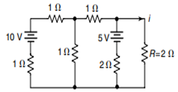
Remove the load \(R = 2\,\Omega\) and find the open-circuit voltage. Applying mesh analysis to the two left loops:
Solving (determinant \(= 11\)):
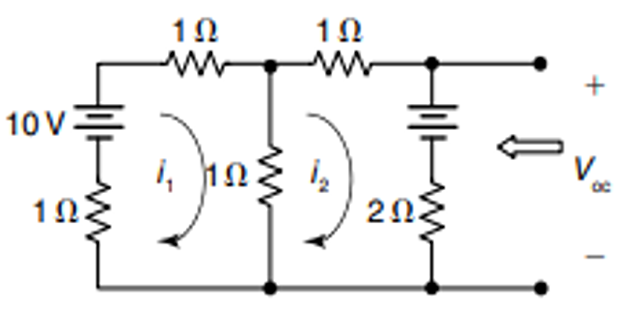
The Thevenin (open-circuit) voltage:
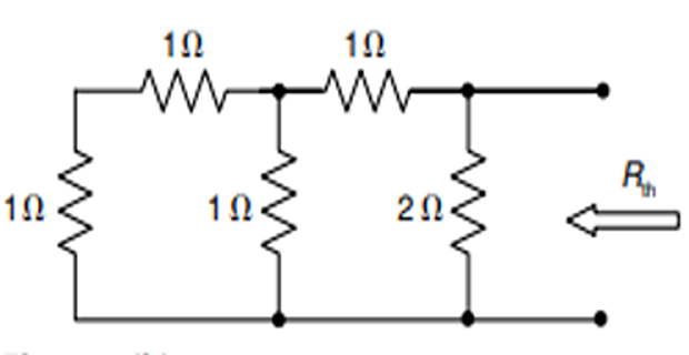
Deactivating the sources, the equivalent resistance seen from the load is:
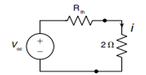
Reconnecting the 2 Ω load, the load current is:
Find the current through the 15 Ω resistor using Thevenin's theorem.
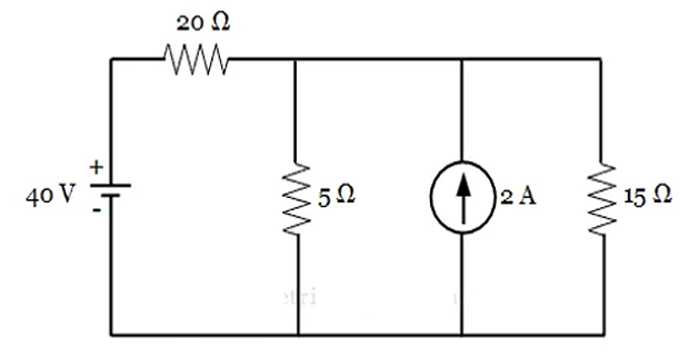
Remove the 15 Ω load. Converting the 2 A–5 Ω pair to a 10 V source in series with 5 Ω and applying KVL:
The open-circuit voltage:
Deactivating the sources, \(R_{TH} = 5 \parallel 20\), then the load current:
Find the Thevenin voltage and resistance at terminals 1–2.
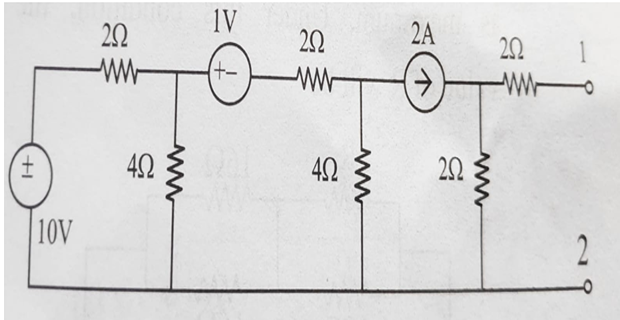
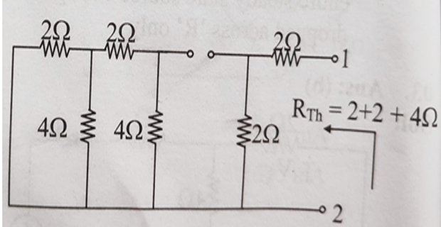
For \(R_{TH}\), short-circuit the voltage sources and open-circuit the current source, then reduce the resistor ladder:
The open-circuit voltage at terminals 1–2:
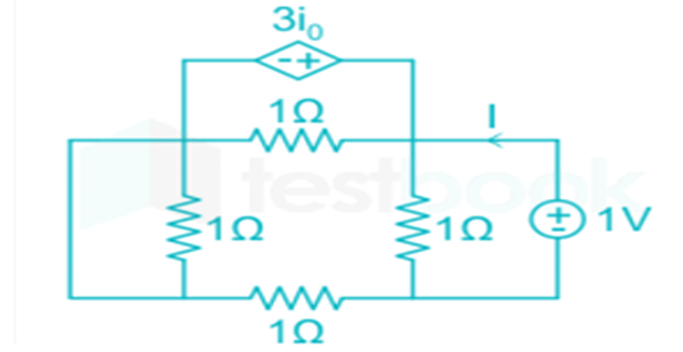
Find the Thevenin resistance at terminals P–Q.
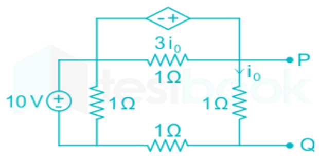
Because the circuit contains a dependent source \(3 i_0\), deactivate the independent 10 V source (short it) and apply a 1 V test source at P–Q. The resulting test current is:
Hence:
Find the current flowing through A–B using Thevenin's theorem.
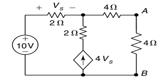
Open-circuit the 4 Ω load. By KCL, with \(v_s = 10 - V_{oc}\) controlling the dependent source \(4 v_s\):

Short-circuit terminals A–B and apply KCL at the node:
The short-circuit current and Thevenin resistance:
Reconnecting the 4 Ω load, the current through A–B:
Find the Thevenin equivalent at terminals a–b.
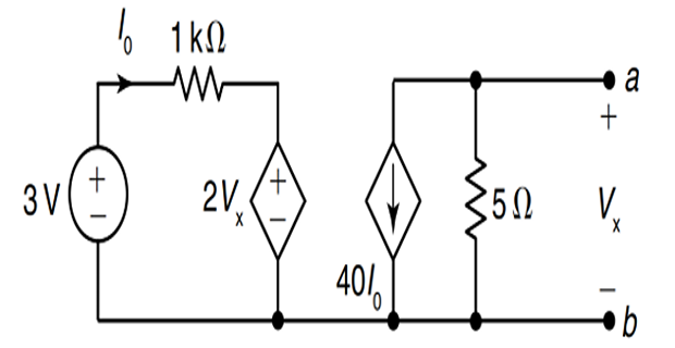
By KVL around the left-hand loop:
In the right-hand loop the dependent current source circulates through the resistor, so by KVL:
Substituting (ii) into (i) gives the open-circuit voltage:
Short-circuiting a–b makes \(V_0 = 0\), so the left loop gives \(I = 10^{-5}\,\text{A}\) and the short-circuit current is:
The Thevenin resistance:
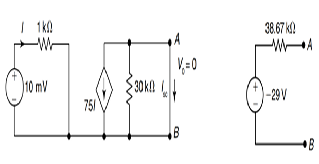
Find the Thevenin resistance at terminals C–D.
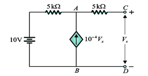
Short the 10 V source and apply a test source \(V_x = 1\,\text{V}\) at C–D. With both 5 kΩ resistors meeting at node A and the dependent source \(10^{-4} V_x\) injecting into A, KCL gives \(V_A = 0.75\,\text{V}\), so the test current is:
Therefore:
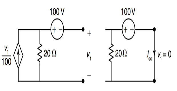
Find the Thevenin equivalent at terminals a–b.
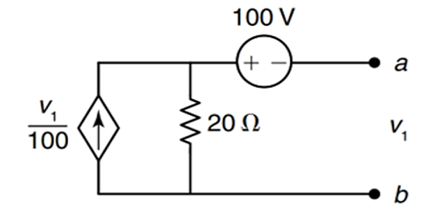
Short-circuit a–b: then \(v_1 = 0\), the dependent source \(v_1/100\) vanishes, and the 100 V source drives the 20 Ω:
Open-circuit a–b and apply KCL (with \(v_1 = v_{oc}\)):
The Thevenin resistance:
Additional Practice Problems
Two self-contained worked examples with schematics: a Thevenin equivalent driven by an independent voltage source, and one driven by a current source.
For the circuit below, find the Thevenin equivalent at terminals a–b and the current delivered to a 4 Ω load. The source is 18 V, with a 6 Ω series resistor and a 3 Ω resistor across the terminals.
Remove the load. The open-circuit voltage is the divider across the 3 Ω resistor:
Deactivating the 18 V source (short), the resistance seen from a–b is the 6 Ω and 3 Ω in parallel:
Reconnecting the 4 Ω load:
A 3 A source has a 6 Ω resistor across it, then a 2 Ω resistor in series to terminal a. Find the Thevenin equivalent at a–b and the current into a 4 Ω load.
Open-circuit a–b. No current flows in the 2 Ω series resistor, so all 3 A flows through the 6 Ω:
Deactivating the current source (open it), the resistance seen from a–b is the 6 Ω and 2 Ω in series:
With a 4 Ω load: