Tutorial 15 — Second-Order Circuits
A second-order circuit contains two energy-storage elements (an inductor and a capacitor) and is governed by a second-order differential equation. Its natural response is fixed by the damping coefficient \(\alpha\) and the undamped natural frequency \(\omega_0\), giving one of three behaviours — overdamped, critically damped, or underdamped. The complete response of a driven circuit is the sum of the forced (final) value and this transient. These problems work through series and parallel \(RLC\) circuits driven by step and switched sources.
For a parallel \(RLC\) circuit, the natural response depends on the relative size of \(\alpha=\dfrac{1}{2RC}\) and \(\omega_0=\dfrac{1}{\sqrt{LC}}\). The roots of the characteristic equation are \(s_{1,2}=-\alpha\pm\sqrt{\alpha^2-\omega_0^{2}}\).
1. Overdamped \(\left(\alpha>\omega_0\right)\), i.e. \(L>4R^{2}C\). The roots are real, distinct and negative:
2. Critically damped \(\left(\alpha=\omega_0\right)\), i.e. \(L=4R^{2}C\). The roots are real and equal:
3. Underdamped \(\left(\alpha<\omega_0\right)\), i.e. \(L<4R^{2}C\). The roots are complex, \(s_{1,2}=-\alpha\pm j\omega_d\) with \(\omega_d=\sqrt{\omega_0^{2}-\alpha^{2}}\):
The constants \(A_1\) and \(A_2\) are found from the initial conditions \(v(0)\) and \(\dfrac{dv(0)}{dt}\).
The unit step \(u(t)\) switches from 0 to 1 at \(t=0\); shifting its argument delays it (\(t_0>0\)) or advances it.
Both topologies share \(\omega_0=\dfrac{1}{\sqrt{LC}}\) and the same three damping cases, but the damping coefficient \(\alpha\) and the overdamping condition differ. This is the single most common source of error, so it is worth fixing in memory.
Series RLC:
Parallel RLC:
General solution procedure: (1) find \(x(0)\) and \(\tfrac{dx(0)}{dt}\) from the \(t=0^{-}\) circuit, using continuity of inductor current and capacitor voltage; (2) find the final value \(x(\infty)\) from the \(t\to\infty\) circuit; (3) compute \(\alpha,\ \omega_0\) and identify the case; (4) write \(x(t)=x(\infty)+\text{transient}\) and solve for the two constants.
Find \(i(t)\) and \(i_R(t)\) for \(t>0\).
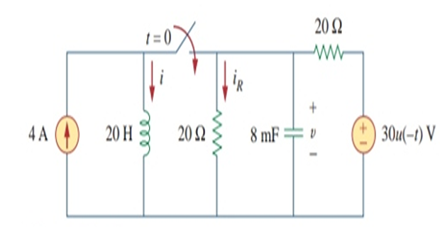
For \(t<0\) the switch is open and the circuit splits into two independent sub-circuits. The 4 A source current flows through the inductor, so
Since \(30u(-t)=30\) for \(t<0\), the voltage source is active. The capacitor behaves as an open circuit, so its voltage equals the voltage across the parallel 20 Ω resistor. By voltage division:
For \(t>0\) the switch is closed and the voltage source (now \(30u(-t)=0\)) acts as a short. This leaves a parallel \(RLC\) circuit fed by the 4 A source, with the two 20 Ω resistors in parallel: \(R=20\parallel20=10\ \Omega\). The characteristic roots are:
Since \(\alpha>\omega_0\) the response is overdamped. With final value \(I_s=4\):
Applying \(i(0)=4\) gives \(A_2=-A_1\). Differentiating (1) and using \(L\dfrac{di(0)}{dt}=v(0)=15\):
Hence the inductor current, and then \(i_R=\dfrac{v}{20}=\dfrac{L}{20}\dfrac{di}{dt}\):
Determine \(v(t)\) for \(t>0\).
Initial conditions from the \(t=0^{-}\) circuit (the 2 A source is active, the 50 V step is off):
For \(t>0\) we have a series \(RLC\) circuit with a step input (\(R=6\ \Omega,\ L=1\ \text{H},\ C=0.04\ \text{F}\)):
The response is underdamped with final capacitor voltage \(V_f=50\):
From \(v(0)=-12=50+A\) we get \(A=-62\). Since \(i(0)=C\dfrac{dv(0)}{dt}=0\):
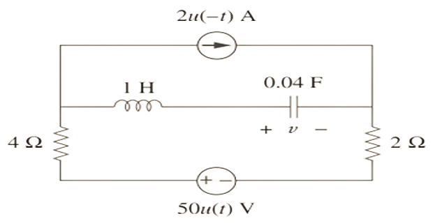
Determine \(v(t)\) for \(t>0\).
Convert the current source to a voltage source. The initial conditions are:
For \(t>0\) we have a series \(RLC\) circuit (\(R=5\ \Omega,\ L=1\ \text{H},\ C=4\ \text{F}\)). Note \(\alpha\) is a positive quantity:
The roots and general solution (final value \(V_s=20\)):
Apply \(v(0)=10\) and \(\dfrac{dv(0)}{dt}=\dfrac{i(0)}{C}=\dfrac{2}{4}=0.5\):
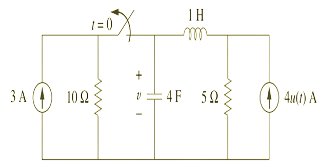
Determine \(i(t)\) for \(t>0\).
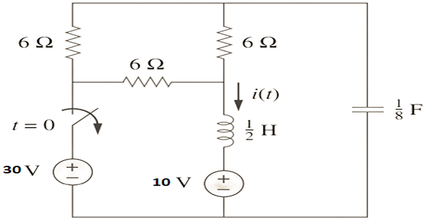
At \(t=0^{-}\), mesh analysis on the resistive network gives:
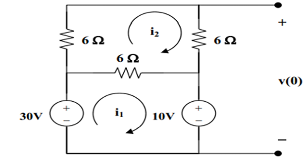
Solving (1) and (2): \(i_1=5,\ i_2=\tfrac{5}{3}\), so the inductor and capacitor initial values are:
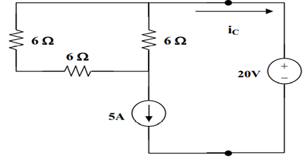
For \(t>0\) we have a series \(RLC\) circuit with \(R=6\parallel12=4\ \Omega\):
With final value \(V_s=10\) and \(v(0)=20\): \(A=10\). Using \(i_C(0)=-5=C(-40+B)\) with \(C=\tfrac18\) gives \(B=0\). Then \(i_C(t)=-\tfrac12(10)e^{-4t}\), and the inductor current is \(i=-i_C\):
The switch moves from \(a\) to \(b\) at \(t=0\). Determine \(i(t)\) for \(t>0\).
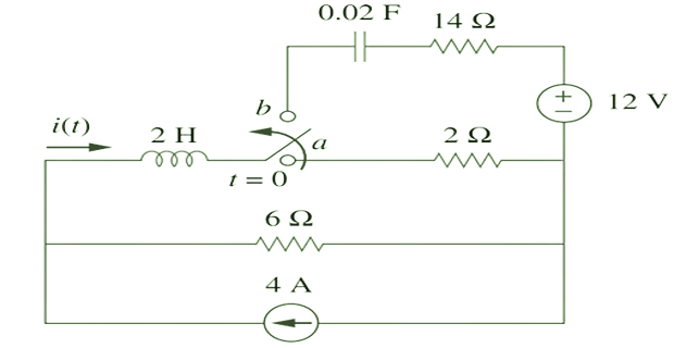
At \(t=0^{-}\) (switch at \(a\)):
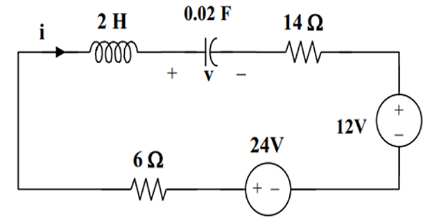
For \(t>0\) (switch at \(b\)) we have a series \(RLC\) circuit:
With final value \(V_s=24-12=12\) and \(v(0)=0\): \(A=-12\). From \(i(0)=3=C(-5A+B)=0.02(60+B)\) we get \(B=90\):
Determine \(i(t)\) and \(v(t)\) for \(t>0\).
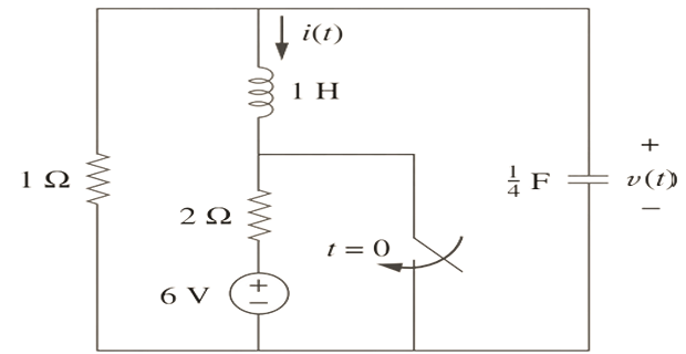
At \(t=0^{-}\):
For \(t>0\) the source is short-circuited, leaving a source-free parallel \(RLC\) circuit (\(R=1,\ L=1,\ C=0.25\)):
Since \(\alpha=\omega_0\) the response is critically damped, \(s_{1,2}=-2\):
Using \(v=L\dfrac{di}{dt}\) at \(t=0\): \(v(0)=2=B+4\Rightarrow B=-2\). Hence:
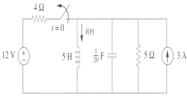
Determine \(i(t)\) for \(t>0\).
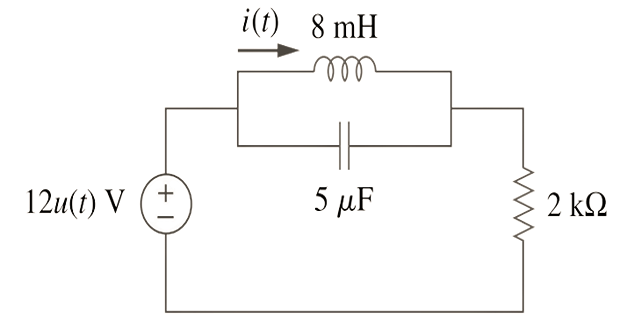
For \(t=0^{-}\), \(u(t)=0\), so \(v(0)=0\) and \(i(0)=0\).
For \(t>0\) we have a parallel \(RLC\) circuit with a step input:
Since \(\alpha<\omega_0\) the response is underdamped, \(s_{1,2}\cong-50\pm j5000\), with final value \(I_s=6\ \text{mA}\):
From \(i(0)=0=6+A\Rightarrow A=-6\ \text{mA}\). From \(v(0)=L\dfrac{di(0)}{dt}=0\): \(5000B-50A=0\Rightarrow B=-0.06\ \text{mA}\). Hence:
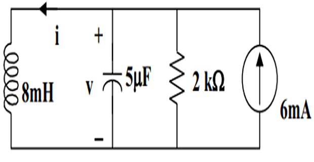
Determine \(i(t)\) for \(t>0\).
For \(t=0^{-}\): \(i(0)=3+\dfrac{12}{4}=6\) and \(v(0)=0\).
For \(t>0\) we have a parallel \(RLC\) circuit with a step input (\(R=5,\ L=5,\ C=0.05\)):
Since \(\alpha=\omega_0\) the response is critically damped, \(s_{1,2}=-2\), with final value \(I_s=3\):
From \(\dfrac{v(0)}{L}=\dfrac{di(0)}{dt}=B-2(3)=0\Rightarrow B=6\):
Determine \(i(t)\) for \(t>0\).
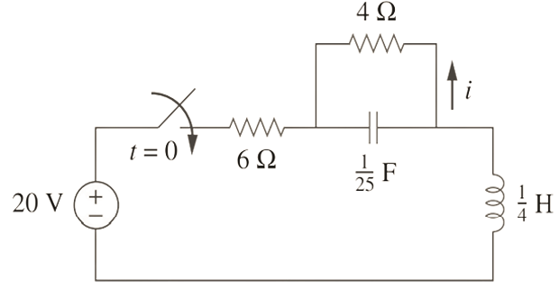
For \(t<0\): \(i(0)=0,\ v(0)=0\). Writing KVL for the two mesh currents (\(i_0\) in the larger loop, \(i\) in the smaller loop):
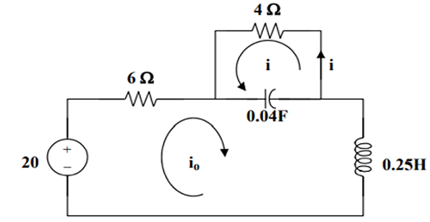
Differentiating (2): \(4\tfrac{di}{dt}+25(i+i_0)=0\Rightarrow i_0=-0.16\tfrac{di}{dt}-i\) (3), and \(\tfrac{di_0}{dt}=0.16\tfrac{d^2i}{dt^2}-\tfrac{di}{dt}\) (4). Substituting into (1):
The characteristic equation \(s^2+30.25s+250=0\) gives underdamped roots:
So \(i(t)=I_s+e^{-15.125t}\left(A_1\cos4.608t+A_2\sin4.608t\right)\). As \(t\to\infty\), \(i_0(\infty)=\tfrac{20}{10}=2=-i(\infty)\), so \(I_s=i(\infty)=-2\) and \(A_1=-I_s=2\). From \(\tfrac{di(0)}{dt}=0\):
The switch has been closed for a long time and is opened at \(t=0\). Determine \(i_x\) and \(v_R\) for \(t>0\).
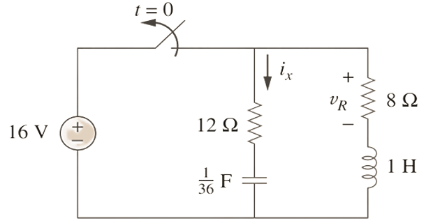
Let \(v\) = capacitor voltage and \(i\) = inductor current. At \(t=0^{-}\) the circuit is in steady state:
By continuity, at \(t=0^{+}\): \(v(0^{+})=16\) and \(i(0^{+})=2\). For \(t>0\) the source is disconnected, leaving a source-free series \(RLC\) circuit with \(R=8+12=20\ \Omega,\ L=1\ \text{H},\ C=\tfrac{1}{36}\ \text{F}\):
Since \(\alpha>\omega_0\) the response is overdamped, \(s_{1,2}=-\alpha\pm\sqrt{\alpha^2-\omega_0^2}=-2,\,-18\), so:
For \(\tfrac{di(0)}{dt}\), KVL around the loop at \(t=0^{+}\) gives \(-v(0)+20i(0)+v_L(0)=0\Rightarrow v_L(0)=16-40=-24\), so \(\tfrac{di(0)}{dt}=\tfrac{v_L(0)}{L}=-24\):
Solving (1) and (2): \(B=1.25,\ A=0.75\). Since the labelled \(i_x=-i\) and \(v_R=8i\):
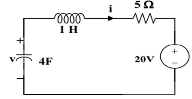
A source-free series \(RLC\) circuit has \(R=10\ \Omega,\ L=1\ \text{H},\ C=\tfrac{1}{16}\ \text{F}\). The initial conditions are \(i(0)=0\) and \(v_C(0)=12\ \text{V}\). Determine the loop current \(i(t)\) for \(t>0\).
Compute the damping parameters for the series circuit:
The real, distinct roots and general solution:
Apply the initial conditions. From \(i(0)=0\): \(A_1+A_2=0\). The inductor slope follows from \(L\tfrac{di(0)}{dt}=v_L(0)=-Ri(0)-v_C(0)=-12\), so \(\tfrac{di(0)}{dt}=-12\):
A source-free parallel \(RLC\) circuit has \(R=2\ \Omega,\ L=0.4\ \text{H},\ C=0.125\ \text{F}\). The initial conditions are \(v(0)=10\ \text{V}\) and \(i_L(0)=0\). Determine the node voltage \(v(t)\) for \(t>0\).
Compute the damping parameters for the parallel circuit:
The damped frequency and general solution:
Apply the initial conditions. From \(v(0)=10\): \(B_1=10\). KCL gives \(C\tfrac{dv(0)}{dt}=-\tfrac{v(0)}{R}-i_L(0)\), so \(\tfrac{dv(0)}{dt}=\tfrac{1}{0.125}\left(-\tfrac{10}{2}-0\right)=-40\):