Tutorial 11 — Maximum Power Transfer Theorem
A linear two-terminal network delivers the greatest power to a load resistance \(R_L\) when that load equals the Thevenin resistance of the network seen from the load terminals, i.e. \(R_L = R_{TH}\). Replacing the network by its Thevenin equivalent \(\big(V_{TH}\ \text{in series with}\ R_{TH}\big)\), the power in a matched load is the maximum possible.
Determine the maximum power delivered to the resistor \(R\).

The first stage is an isolated divider. The voltage controlling the dependent source is the drop across the 2 kΩ resistor:
Remove \(R\). The open-circuit (Thevenin) voltage is the drop across the 40 kΩ resistor in the second stage:
Short the load terminals. This shorts out the 40 kΩ, leaving only the 10 kΩ across the 200 V source:
The Thevenin resistance, and the matched load that draws maximum power:

With \(R = R_{TH} = 8\ \text{k}\Omega\), the maximum power is:
Determine the value of \(R_L\) for maximum power transfer.
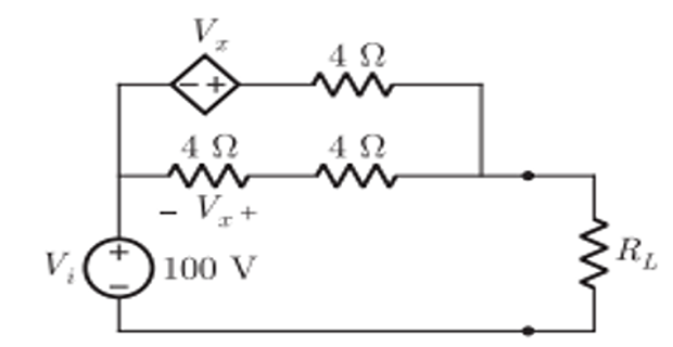
The network contains a dependent source, so deactivate the independent 100 V source (short it) and apply a test source \(V_1\) that injects a test current \(I_1\) at the load terminals. With \(V_x\) the controlling voltage across the middle 4 Ω, KVL around the test loop gives:

The controlling term cancels, so the Thevenin resistance is independent of \(V_x\):
Maximum power is transferred when the load is matched to this resistance, \(R_L = R_{TH}\).
Find the value of \(R\) in the circuit such that maximum power transfer takes place. What is the amount of this power?

Remove \(R\) and find the open-circuit voltage. Mesh analysis on the two left loops gives:

From Mesh-2, \(i_1 = 4i_2\); substituting into Mesh-1 gives \(10i_2 = 4\), hence:
The current \(i_2\) flows through the right-hand 1 Ω resistor. Walking from the bottom rail through that resistor and the 6 V source to the open terminal:
For \(R_{TH}\), deactivate both voltage sources (short them) and look back into the load terminals. The left 1 Ω and the 2 Ω are in parallel at the upper-left node, in series with the 5 Ω, all in parallel with the right-hand 1 Ω:
Maximum power transfer requires \(R = R_{TH} = \tfrac{17}{20}\,\Omega\), giving:
Additional Practice Problems
Three self-contained worked examples with schematics: a matched load on an independent voltage source, the same idea applied to a current source, and the efficiency of power transfer at the matched condition.
A 12 V source with a 6 Ω series resistance feeds a variable load \(R_L\). Find the value of \(R_L\) for maximum power transfer and the corresponding power.
The source is already in Thevenin form: \(V_{TH} = 12\ \text{V}\) and \(R_{TH} = 6\ \Omega\). Maximum power transfer requires a matched load:
The maximum power delivered to that load is:
A 3 A current source has a 4 Ω resistor across it and feeds a load \(R_L\) at terminals a–b. Find \(R_L\) for maximum power transfer and the power delivered.
Open-circuit a–b. With no load current, all 3 A flows through the 4 Ω, so the open-circuit voltage is:
Deactivate the current source (open it); the resistance seen from a–b is just the 4 Ω. Maximum power transfer requires:
The maximum power delivered is then:
A source of Thevenin voltage \(V_{TH}\) and resistance \(R_{TH}\) delivers maximum power to a matched load \(R_L = R_{TH}\). What fraction of the total power produced by the source actually reaches the load?
With \(R_L = R_{TH}\), the loop current is:
The power delivered to the load and the total power produced by the source are:
The efficiency of power transfer is therefore: