Tutorial 8 — Norton's Theorem
Any linear two-terminal network can be replaced by a single current source \(I_N\) (the short-circuit current at the terminals) in parallel with a resistance \(R_N\). The Norton resistance equals the Thevenin resistance, \(R_N = R_{TH}\). These problems cover finding the equivalent for circuits with independent sources (using KCL, superposition, and source transformation) and dependent sources (using the open-circuit/short-circuit method), and then using the equivalent to obtain a load current or voltage.
Determine the Norton equivalent current and resistance at terminals a–b. The network is a 20 V source in series with a 24 Ω resistor, in parallel with a 2 A current source (directed downward) across the terminals.
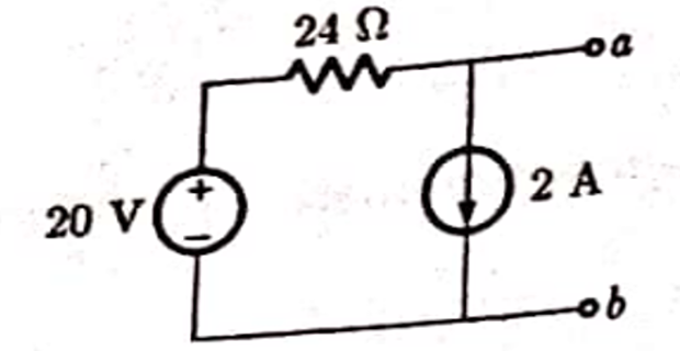
For the Norton resistance, deactivate the sources — short the 20 V source and open the 2 A source. Only the 24 Ω resistor then connects a to b:
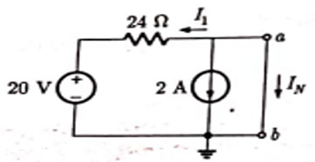
For the Norton current, short terminals a–b. With a at the reference potential, the 20 V source drives a current \(I_1 = \tfrac{20}{24} = \tfrac{5}{6}\ \text{A}\) through the 24 Ω into the node. Applying KCL at node a (taking currents into the short-circuit branch):
Determine \(V_0\) across the 1 kΩ load using Norton's theorem.
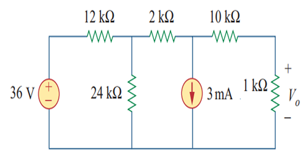
Remove the 1 kΩ load and find the Norton resistance. Deactivating the sources (short the 36 V source, open the 3 mA source), the resistance seen from the load terminals is:
The Norton (short-circuit) current is found by superposition, \(I_N = I_v + I_i\), activating one source at a time.

aVoltage source only (3 mA open). Transforming the 36 V–12 kΩ pair to a 3 mA source with a shunt \(12 \parallel 24 = 8\ \text{k}\Omega\), current division to the short gives:
bCurrent source only (36 V shorted). The node feeding the short sees two equal 10 kΩ paths, so the 3 mA splits equally; the part reaching the short opposes the reference direction:
Superposing the two contributions:
Reconnecting the 1 kΩ load to the Norton equivalent (\(I_N\) in parallel with \(R_N = 20\ \text{k}\Omega\)), the output voltage is the current through the 1 kΩ times 1 kΩ:
Determine the Norton equivalent current and resistance at terminals a–b. A 120 V source feeds a 20 Ω resistor into a parallel combination of a current source and a 40 Ω resistor, with a 12 Ω resistor across a–b.
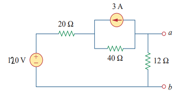
Note: the worked solution uses a current source of 2 A. The transformed 80 V branch in the figure equals \(2\ \text{A}\times 40\ \Omega\); a 3 A value would make the network degenerate (\(I_N = 0\)), so 2 A is the consistent value.
For the Norton resistance, deactivate the sources (short the 120 V source, open the current source). The 20 Ω and 40 Ω are then in series and that combination is in parallel with the 12 Ω:
For the Norton current, short a–b (the 12 Ω carries no current). Transform the 2 A–40 Ω pair into an 80 V source in series with 40 Ω, then apply KVL around the resulting single loop:

Determine the current \(i\) through the 5 Ω resistor using a Norton equivalent. Replace the network to the left of a–b by its Norton equivalent, then recombine with the 5 Ω resistor and 4 A source on the right.
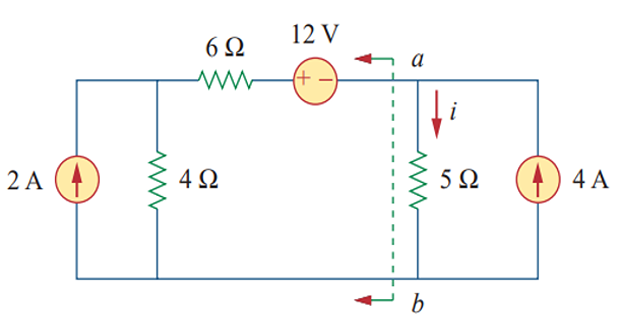
For the left network, deactivate its sources (open the 2 A source, short the 12 V source). The 6 Ω and 4 Ω are then in series at a–b:
For the left short-circuit current, short a–b and let \(v\) be the node between the 4 Ω and 6 Ω. KCL at that node gives:
Hence the left Norton current:
Combining with the right-hand side: the 4 A source and the −0.4 A Norton source drive the parallel combination of \(R_N = 10\ \Omega\) and the 5 Ω resistor. By current division through the 5 Ω:
Find the Norton equivalent circuit at terminals a–b. The network contains a dependent current source \(2 i_1\) controlled by the current \(i_1\) in the middle 2 Ω resistor.
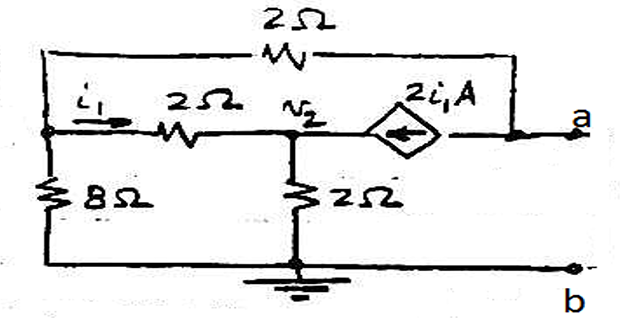
Because there are no independent sources, the short-circuit current is found directly. Short a–b and write nodal equations. KCL at node \(v_1\):
KCL at node \(v_2\), with the dependent source \(2 i_1\) feeding the node:
The controlling current is the branch current through the middle 2 Ω:
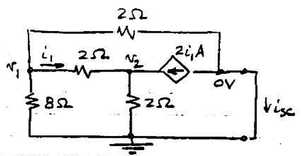
Solving the three equations gives both node voltages zero, so the short-circuit current is zero:
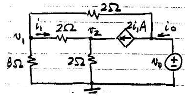
With \(I_N = i_{sc} = 0\), the Norton resistance is obtained by applying a test source \(v_0\) at a–b and measuring the resulting current \(i_0\):

Additional Practice Problems
Two self-contained worked examples with schematics: a Norton equivalent driven by an independent voltage source, and one driven by a current source.
For the circuit below, find the Norton equivalent at terminals a–b and the current delivered to a 6 Ω load. The source is 24 V, with a 4 Ω series resistor and a 12 Ω resistor across the terminals.
Remove the 6 Ω load and short terminals a–b. The 12 Ω is then short-circuited and carries no current, so the full short-circuit current is set by the 24 V source and the 4 Ω:
Deactivating the source (short it), the resistance seen from a–b is the 4 Ω and 12 Ω in parallel:
Reconnecting the 6 Ω load to the Norton source, current division gives the load current:
A 6 A source has a 3 Ω resistor across it, then a 6 Ω resistor in series to terminal a. Find the Norton equivalent at a–b and the current into a 9 Ω load.
Short terminals a–b. The 6 A from the source divides between the 3 Ω shunt and the 6 Ω series branch leading to the short; the short-circuit current is the part through the 6 Ω:
Deactivating the current source (open it), the resistance seen from a–b is the 3 Ω and 6 Ω in series:
With a 9 Ω load on the Norton source, current division gives: