Tutorial 16 — Theorems in Frequency Domain
The network theorems used for DC resistive circuits carry over directly to sinusoidal steady-state analysis once every element is replaced by its phasor impedance. After converting sources to phasors and inductors/capacitors to \(j\omega L\) and \(1/j\omega C\) , the same tools—current and voltage division, mesh and nodal analysis, Thevenin's and Norton's theorems, source transformation, and maximum power transfer—apply with complex arithmetic. These problems work through each method in the frequency domain.
AC Analysis · Electric Circuit Analysis · 15 solved problems
Fundamentals — Voltage & Current Division
Phasor versions of the current- and voltage-divider relations applied to circuits containing impedances.
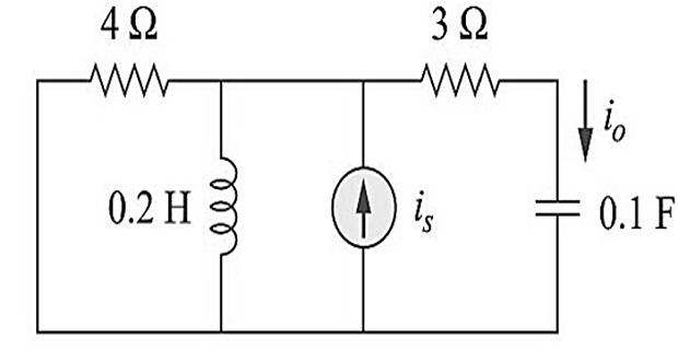
If \(i_s = 5\cos(10t+40^{\circ})\) A, determine \(i_0\) .
Solution
With \(\omega = 10\) rad/s, convert the source to a phasor and the storage elements to impedances:
\[\begin{aligned}
\mathrm{i}_{\mathrm{s}}=& 5 \cos \left(10 \mathrm{t}+40^{\circ}\right) \rightarrow \mathbf{I}_{\mathrm{s}}=5 \angle 40^{\circ}\\
0.1 \mathrm{~F} &\longrightarrow \frac{1}{j \omega \mathrm{C}}=\frac{1}{j(10)(0.1)}=-j \\
0.2 \mathrm{H} &\longrightarrow j \omega \mathrm{L}=j(10)(0.2)=j 2
\end{aligned}\]
Group the impedances and apply the current-divider rule (\(\mathbf{I}_o\) is the current diverted into the \(\mathbf{Z}_2\) branch):
\[\begin{aligned}
&\mathbf{Z}_{1}=4 \,\|\, \mathrm{j} 2=\frac{\mathrm{j} 8}{4+\mathrm{j} 2}=0.8+\mathrm{j} 1.6, \qquad \mathbf{Z}_{2}=3-\mathrm{j} \\
&\mathbf{I}_{\mathrm{o}}=\frac{\mathbf{Z}_{1}}{\mathbf{Z}_{1}+\mathbf{Z}_{2}} \mathbf{I}_{\mathrm{s}}=\frac{0.8+\mathrm{j} 1.6}{3.8+\mathrm{j} 0.6}\left(5 \angle 40^{\circ}\right) \\
&\mathbf{I}_{\mathrm{o}}=\frac{\left(1.789 \angle 63.43^{\circ}\right)\left(5 \angle 40^{\circ}\right)}{3.847 \angle 8.97^{\circ}}=2.325 \angle 94.46^{\circ}
\end{aligned}\]
Answer \(i_o(t)=2.325 \cos\left(10t+94.46^{\circ}\right)\ \text{A}\)
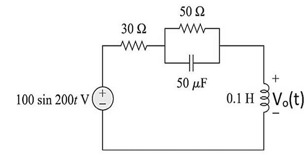
Calculate \(v_0(t)\) in the given figure.
Solution
At \(\omega = 200\) rad/s, the element impedances are:
\[\begin{aligned}
50 \mu \mathrm{F} &\longrightarrow \frac{1}{\mathrm{j} \omega \mathrm{C}}=\frac{1}{\mathrm{j}(200)\left(50 \times 10^{-6}\right)}=-\mathrm{j} 100 \\
0.1~\mathrm{H} &\longrightarrow j\omega L = j(200)(0.1) = j20
\end{aligned}\]
Combine the parallel branch, then apply voltage division:
\[\begin{gathered}
50 \,\|\,(-\mathrm{j} 100)=\frac{(50)(-\mathrm{j} 100)}{50-\mathrm{j} 100}=\frac{-\mathrm{j} 100}{1-\mathrm{j} 2}=40-\mathrm{j} 20 \\
\mathbf{V}_{\mathrm{o}}=\frac{\mathrm{j} 20}{\mathrm{j} 20+30+40-\mathrm{j} 20}\left(60 \angle 0^{\circ}\right)=\frac{\mathrm{j} 20}{70}\left(60 \angle 0^{\circ}\right)=17.14 \angle 90^{\circ}
\end{gathered}\]
Answer \(v_o(t)=17.14 \sin(200 t+90^{\circ})=17.14 \cos(200t)\ \text{V}\)
KCL, KVL, Mesh & Nodal Analysis
Systematic loop and node equations written directly in terms of phasors and complex impedances.
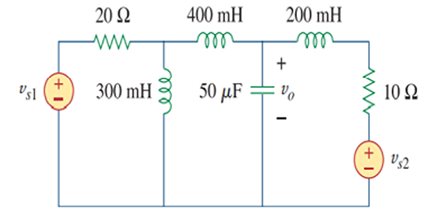
Use mesh analysis to find \(v_0\) if \(V_{s1} = 120\cos (100t+90^{\circ})\) V and \(V_{s2} = 80 \cos 100t\) V.
Solution
At \(\omega = 100\) rad/s, convert each element to its impedance:
\[\begin{array}{ll}
300 \mathrm{mH} & \longrightarrow j \omega L=j 100 \times 300 \times 10^{-3}=j 30 \\
200 \mathrm{mH} & \longrightarrow j \omega L=j 100 \times 200 \times 10^{-3}=j 20 \\
400 \mathrm{mH} & \longrightarrow j \omega L=j 100 \times 400 \times 10^{-3}=j 40 \\
50 \mu \mathrm{F} & \longrightarrow 1 / j \omega \mathrm{C}=\frac{1}{j 100 \times 50 \times 10^{-6}}=-j 200
\end{array}\]
Write KVL around the three meshes:
\[\begin{aligned}
\text{Mesh-1} \Rightarrow & -120\angle 90^{\circ}+(20+j30)I_1-j30I_2=0 \\
\text{Mesh-2} \Rightarrow & -j30\,I_1+(j30+j40-j200)I_2+j200I_3=0\\
\text{Mesh-3} \Rightarrow & \;80+j200I_2+(10-j180)I_3=0
\end{aligned}\]
In matrix form (each row divided through to simplify):
\[\left[\begin{array}{ccc}
2+\mathrm{j} 3 & -\mathrm{j} 3 & 0 \\
-3 & -13 & 20 \\
0 & \mathrm{j} 20 & 1-\mathrm{j} 18
\end{array}\right]\left[\begin{array}{c}
\mathrm{I}_{1} \\ \mathrm{I}_{2} \\ \mathrm{I}_{3}
\end{array}\right]=\left[\begin{array}{c}
\mathrm{j} 12 \\ 0 \\ -8
\end{array}\right]\]
Solving the system gives \(\mathbf{I}_2-\mathbf{I}_3 = -0.157+j0.2334\) A. The output voltage is taken across the \(-j200\) capacitor:
\[\begin{aligned}
\mathrm{V}_{\mathrm{o}}&=-\mathrm{j} 200\left(\mathrm{I}_{2}-\mathrm{I}_{3}\right)=-\mathrm{j} 200(-0.157+\mathrm{j} 0.2334)\\
&=46.68+\mathrm{j} 31.4=56.26 \angle 33.93^{\circ}\ \mathrm{V}
\end{aligned}\]
Answer \(v_o(t)=56.26 \cos(100t+33.93^{\circ})\ \text{V}\)
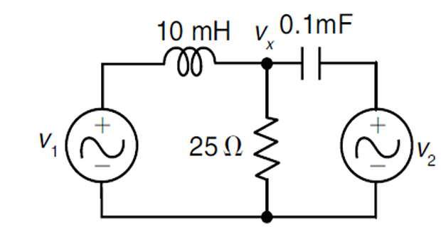
Find \(V_x\) if \(V_1(t)=20\cos 1000t\) V and \(V_2(t)=20\sin 1000t\) V.
Solution
At \(\omega = 10^3\) rad/s:
\[\begin{aligned}
X_L &= j\omega L = j10~\Omega, \qquad X_C = \dfrac{-j}{\omega C} = -j10~\Omega\\
V_1 &= 20\angle 0^{\circ}, \qquad V_2 = 20\angle -90^{\circ}
\end{aligned}\]
KCL at node \(x\) : \(\dfrac{V_{x}-20 \angle 0^{\circ}}{j 10}+\dfrac{V_{x}-20 \angle-90^{\circ}}{-j 10}+\dfrac{V_{x}}{25}=0\) . The two reactive terms in \(V_x\) cancel:
\[\begin{aligned}
&\Rightarrow V_{x}\left[\frac{1}{j 10}-\frac{1}{j 10}+\frac{1}{25}\right]=\frac{20 \angle 0^{\circ}}{j 10}+\frac{20 \angle-90^{\circ}}{-j 10} \\
&\Rightarrow \frac{V_{x}}{25}=(2-j 2) \Rightarrow V_{x}=50-j 50=70.71 \angle-45^{\circ}\ (\mathrm{V})
\end{aligned}\]
Answer \(v_{x}(t)=70.71 \cos \left(1000 t-45^{\circ}\right)\ \text{V}\)
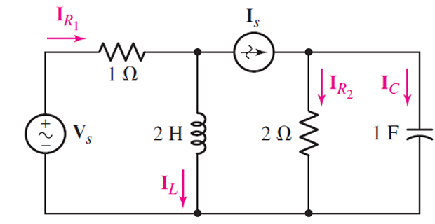
Determine \(I_{R2}(t)\) and \(I_s(t)\) if both sources operate at \(\omega = 2\) rad/s and \(I_c = 2\angle 28^{\circ}\) A.
Solution
The capacitor voltage and the current in the \(2\ \Omega\) resistor follow directly:
\[\begin{aligned}
V_c &= \dfrac{1}{j\omega C}\, I_c = (0.5\angle-90^{\circ})(2\angle 28^{\circ}) = 1\angle -62^{\circ}~\mathrm{V}\\
I_{R2} &= \dfrac{V_c}{2} = 0.5 \angle -62^{\circ}~\mathrm{A}
\end{aligned}\]
By KCL the source current is the phasor sum (the two terms are nearly \(90^{\circ}\) apart, so they must be added as vectors, not magnitudes):
\[I_s = I_{R2}+I_c = 0.5\angle -62^{\circ} + 2\angle 28^{\circ} = 2.06\angle 13.96^{\circ}~\mathrm{A}\]
Answer \(i_{R2}(t)=0.5\cos(2t-62^{\circ})\ \text{A},\quad i_s(t)=2.06\cos(2t+13.96^{\circ})\ \text{A}\)
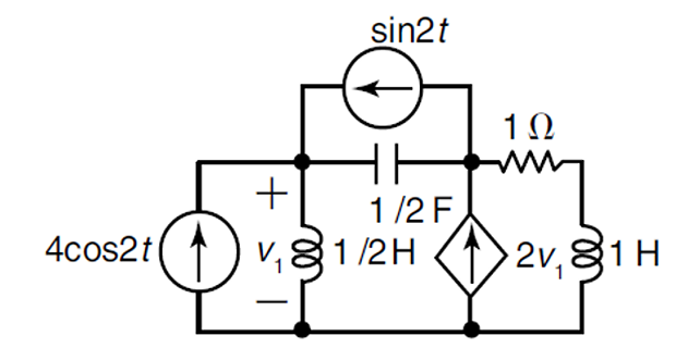
Determine \(v_1\) .
Solution
At \(\omega = 2\) rad/s, with \(L_1 = 0.5\) H, \(L_2 = 1\) H and \(C = 0.5\) F:
\[X_{L1} = j1~\Omega, \quad X_{L2} = j2~\Omega, \quad X_{c} = -j1~\Omega\]
Write KCL at the two non-reference nodes:
\[\begin{aligned}
\text{Node (1):}~ & \frac{V_{1}}{j 1}-4 \angle 0^{\circ}-1 \angle-90^{\circ}+\frac{V_{1}-V_{2}}{-j 1}=0\\
\text{Node (2):}~ & \frac{V_{2}-V_{1}}{-j 1}-2 V_{1}+\frac{V_{2}}{1+j 2}+1 \angle-90^{\circ}=0
\end{aligned}\]
Solving the pair of node equations gives \(V_{1}=1 \angle-36.87^{\circ}\) V.
Answer \(v_{1}(t)=\cos \left(2 t-36.87^{\circ}\right)\ \text{V}\)
Thevenin's & Norton's Theorems
Reducing a linear AC network to an equivalent phasor source \(V_{TH}\) in series with a complex impedance \(Z_{TH}\) .
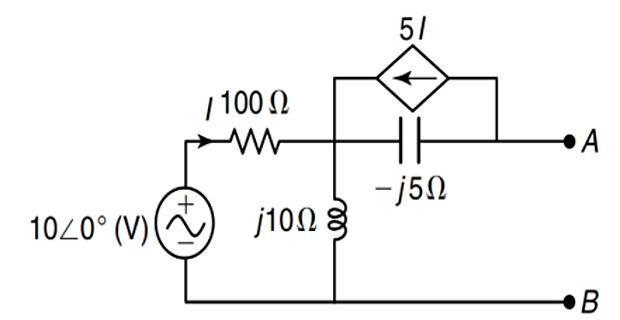
Find the Thevenin equivalent with respect to terminals A–B for the circuit shown.
Solution
Step 1 Open-circuit (Thevenin) voltage. The mesh current and the open-circuit voltage across A–B are:
\[\begin{aligned}
I &= \dfrac{10\angle 0^{\circ}}{100+j10} = 0.0995\angle -5.7^{\circ}~\mathrm{A}\\
V_{Th}&=V_{AB} = \left(I\times j 10\right)-\left(5I\times (-j5)\right) = 3.48\angle 84.3^{\circ} ~\mathrm{V}
\end{aligned}\]
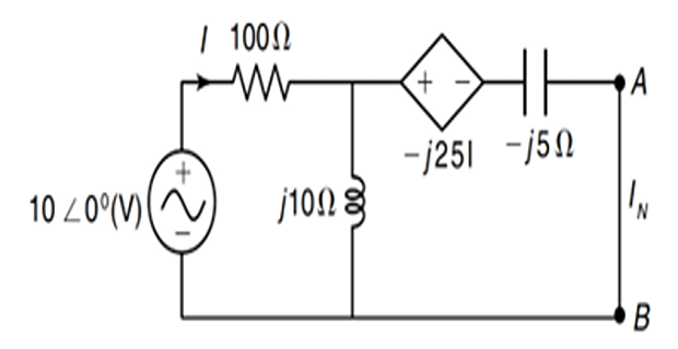
Step 2 Short-circuit A–B and solve for the Norton (short-circuit) current:
\[\begin{aligned}
10\angle 0^{\circ} &= (100+j10)I-j10\,I_N \quad\cdots (1) \\
j25\,I &= -j10\,I+I_N(j10-j5) \quad\cdots (2)\\
\text{Solving} ~&\Rightarrow~ I_N = 0.6\angle 31^{\circ}~\mathrm{A}
\end{aligned}\]
Step 3 The Thevenin impedance is the ratio of open-circuit voltage to short-circuit current:
\[Z_{Th} = \dfrac{V_{Th}}{I_N} = \dfrac{3.48\angle 84.3^{\circ}}{0.6\angle 31^{\circ}} = 5.8 \angle 53.3^{\circ} ~\Omega\]
Answer \(V_{Th}=3.48\angle 84.3^{\circ}\ \text{V},\quad Z_{Th}=5.8\angle 53.3^{\circ}\ \Omega\)
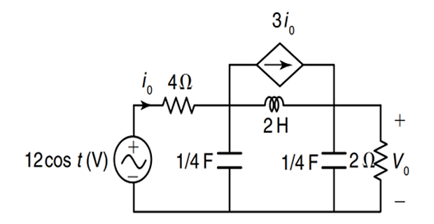
Find \(V_0\) (the voltage across the \(2\ \Omega\) load) using Thevenin's theorem.
Solution
Step 1 Remove the \(2\ \Omega\) load (open circuit) and find the open-circuit voltage. With \(i_0 = I_1\) :
\[\begin{aligned}
\text{KVL-1:} & ~(4-j4)I_1+j4I_2 = -12 \\
\text{KVL-2:} & ~-j2I_1+(-j6)I_2 = 0\\
\text{Solving} ~ I_2 &= 0.6\angle 53.13^{\circ} ~\mathrm{A} \\
V_{Th} &= I_2 \times (-j8) = 4.8\angle -36.87^{\circ} ~\mathrm{V}
\end{aligned}\]
Step 2 Short-circuit the terminals to obtain the Norton current and hence the Thevenin impedance:
\[\begin{aligned}
\text{KVL:} ~& (4-j4)I_1+j4I_2 = -12\\
\text{Solving} ~I_2 &= I_N = 1.34\angle 63.43^{\circ}~\mathrm{A} \\
Z_{Th} &= \dfrac{V_{Th}}{I_N} = 3.58\angle -100.3^{\circ}~\Omega
\end{aligned}\]
Step 3 Reconnect the \(2\ \Omega\) load. The load current and the voltage across it are:
\[\begin{aligned}
I_0 &= \dfrac{V_{Th}}{Z_{Th}+2} = \dfrac{4.8\angle -36.87^{\circ}}{1.36-j3.52} = 1.27\angle 32^{\circ}~\mathrm{A}\\
V_0 &= I_0 \times 2 = 2.54\angle 32^{\circ}~\mathrm{V}
\end{aligned}\]
Answer \(V_0 = 2.54\angle 32^{\circ}\ \text{V}\)
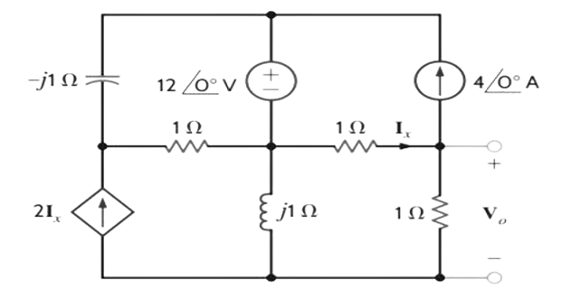
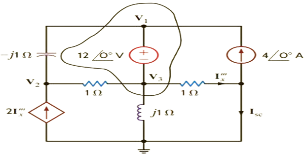
Find the voltage \(V_0\) across the \(1\ \Omega\) resistor.
Solution
Step 1 With the \(1\ \Omega\) resistor removed, write the node equations (the controlling current is \(\mathbf{I}_x'''=V_3\) ):
\[\begin{aligned}
\mathbf{V}_{3}+12 \angle 0^{\circ} &=\mathbf{V}_{1} \\
\frac{\mathbf{V}_{2}-\mathbf{V}_{1}}{-j 1}+\frac{\mathbf{V}_{2}-\mathbf{V}_{3}}{1}-2 \mathbf{I}_{x}^{\prime \prime \prime} &=0 \\
\frac{\mathbf{V}_{1}-\mathbf{V}_{2}}{-j 1}+\frac{\mathbf{V}_{3}-\mathbf{V}_{2}}{1}-4 \angle 0^{\circ}+\frac{\mathbf{V}_{3}}{j 1}+\mathbf{I}_{x}^{\prime \prime \prime} &=0 \\
\mathbf{I}_{x}^{\prime \prime \prime} &=\frac{\mathbf{V}_{3}}{1}
\end{aligned}\]
Step 2 In matrix form:
\[\left[\begin{array}{cccc}
-1 & 0 & 1 & 0 \\
-\mathrm{j} & (1+\mathrm{j}) & -1 & -2 \\
\mathrm{j} & -(1+\mathrm{j}) & 1-\mathrm{j} & 1 \\
0 & 0 & -1 & 1
\end{array}\right]\left[\begin{array}{c}
\mathbf{V}_{1} \\ \mathbf{V}_{2} \\ \mathbf{V}_{3} \\ \mathbf{I}_{x}^{\prime \prime \prime}
\end{array}\right]=\left[\begin{array}{r}
-12 \\ 0 \\ 4 \\ 0
\end{array}\right]\]
Step 3 Solving gives the controlling current, and from it the short-circuit current:
\[\begin{aligned}
\mathbf{I}_x^{\prime\prime\prime}& = 2.8284\angle 135^{\circ}~\mathrm{A} \\
\mathbf{I}_{sc}& = \mathbf{I}_x^{\prime\prime\prime}-4\angle 0^{\circ} = 6.3245\angle 161.57^{\circ}~\mathrm{A}
\end{aligned}\]
Step 4 With \(Z_{Th}=(1-j)\ \Omega\) , the voltage across the reconnected \(1\ \Omega\) resistor is found from the Norton equivalent:
\[V_0 = \mathbf{I}_{sc}\left[\frac{(1)(1-j)}{1+1-j}\right] = 4 \angle 143.13^{\circ} ~\mathrm{V}\]
Answer \(V_0 = 4\angle 143.13^{\circ}\ \text{V}\)
Source Transformation
Interchanging practical voltage and current sources through their series/parallel impedance to simplify the network step by step.
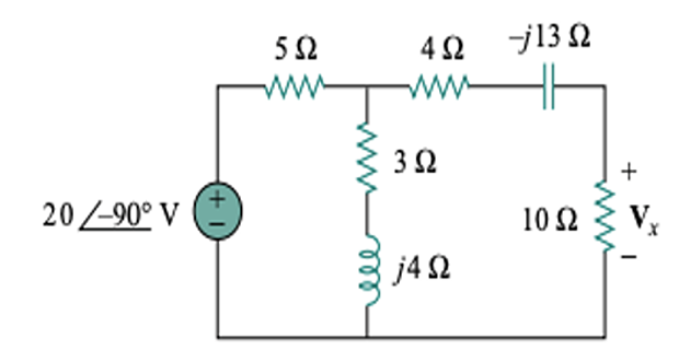
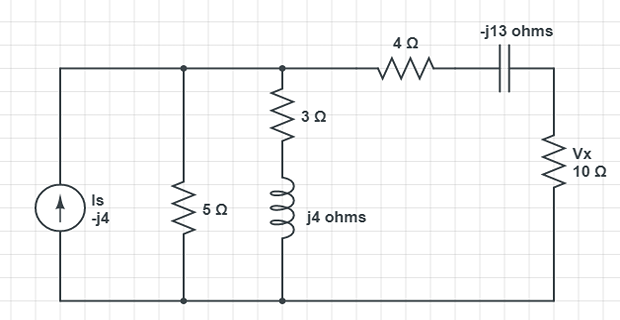
Calculate \(V_x\) using the method of source transformation.
Solution
Step 1 Transform the voltage source to a current source and combine the \(5\ \Omega\) resistance in parallel with the \((3+j4)\) impedance:
\[\mathbf{I}_{s}=\frac{20 \angle -90^{\circ}}{5}=4 \angle-90^{\circ}=-j 4~\mathrm{A}\]
\[\mathbf{Z}_{1}=\frac{5(3+j 4)}{8+j 4}=2.5+j 1.25~\Omega\]
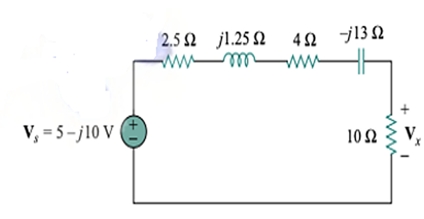
Step 2 Convert the current source back to a voltage source:
\[\mathbf{V}_{s}=\mathbf{I}_{s} \mathbf{Z}_{1}=-j 4(2.5+j 1.25)=5-j 10~\mathrm{V}\]
Step 3 Apply voltage division to obtain \(V_x\) across the \(10\ \Omega\) resistor:
\[\mathbf{V}_{x}=\frac{10}{10+2.5+j 1.25+4-j 13}(5-j 10)=5.519 \angle-28^{\circ}~\mathrm{V}\]
Answer \(\mathbf{V}_x = 5.519\angle -28^{\circ}\ \text{V}\)
Maximum Power Transfer Theorem
For maximum average power, the load impedance is the complex conjugate of the Thevenin impedance, \(Z_L=Z_{TH}^{*}\) .
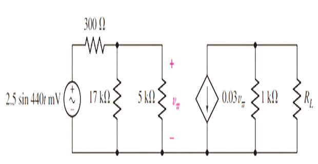
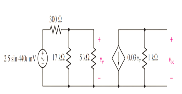
Choose a load resistance so that maximum power is transferred to it, and calculate the actual power transferred.
Solution
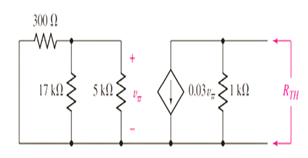
Step 1 Since \(v_{\pi}=0\) , the dependent current source acts as an open circuit, so \(R_{TH}=1\ \mathrm{k}\Omega\) . This is confirmed by connecting an independent \(1\ \mathrm{A}\) test source across the \(1\ \mathrm{k}\Omega\) resistor: \(v_{\pi}\) remains zero, so the dependent source stays inactive and contributes nothing to \(R_{TH}\) .
Step 2 For maximum power, set \(R_{L}=R_{TH}=1\ \mathrm{k}\Omega\) . The open-circuit voltage is
\[v_{\mathrm{oc}}=-0.03\, v_{\pi}(1000)=-30 v_{\pi}\]
where \(v_{\pi}\) follows from voltage division:
\[v_{\pi}=\left(2.5 \times 10^{-3} \sin 440 t\right)\left(\frac{3864}{300+3864}\right)\]
so the Thevenin equivalent is a source \(-69.6 \sin 440 t\ \mathrm{mV}\) in series with \(1\ \mathrm{k}\Omega\) .
Step 3 The maximum (time-varying) power delivered to the load is
\[p_{\max }=\frac{v_{TH}^{2}}{4 R_{TH}}=1.211 \sin ^{2} 440 t~\mu \mathrm{W}\]
Answer \(R_L = 1\ \mathrm{k}\Omega,\quad p_{\max}=1.211\sin^2 440t\ \mu\text{W}\)
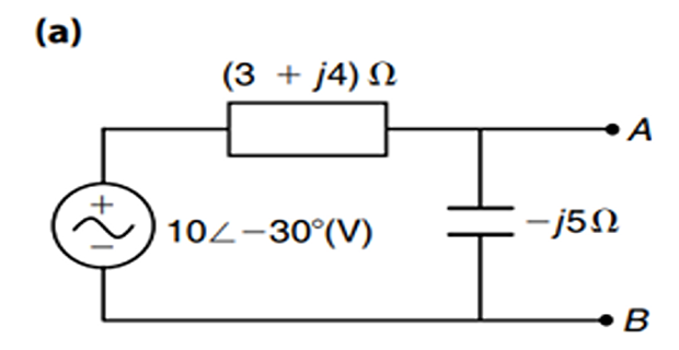
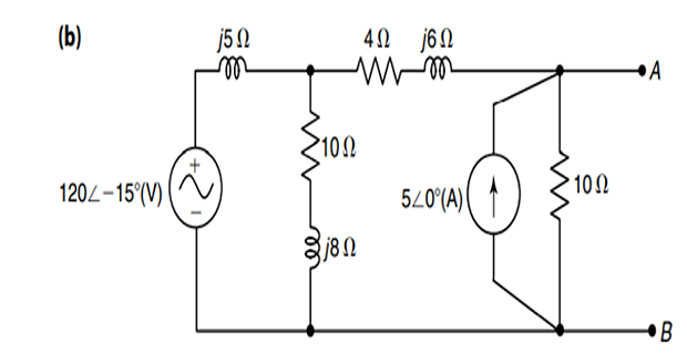
A loudspeaker is connected across terminals A and B of the network. What impedance should it have to obtain maximum power dissipation in it?
Solution
(a) The equivalent impedance seen from terminals A–B is
\[Z_{\text {th }}=\frac{(3+j 4)(-j 5)}{3+j 4-j 5}=7.9 \angle-18.43^{\circ} \Omega=(7.5-j 2.5)\ \Omega\]
For maximum power transfer, \(Z_{L}=Z_{\text {th }}^{*}=(7.5+j 2.5)\ \Omega\) .
(b) For the second network, the equivalent impedance at A–B is
\[\begin{aligned}
Z_{\mathrm{th}} &=\left[\frac{(10+j 8) j 5}{10+j 8+j 5}+4+j 6\right] \,\|\, 10\\
&=\left(\frac{-40+j 50+40+j 52+j 60-78}{10+j 13}\right) \,\|\, 10 \\
&=6.14 \angle 30^{\circ} \Omega=(5.316+j 3.07)\ \Omega
\end{aligned}\]
so that \(Z_{L}=Z_{\text {th }}^{*}=6.14 \angle-30^{\circ} \Omega=(5.316-j 3.07)\ \Omega\) .
Answer \(\text{(a) } Z_L=(7.5+j2.5)\ \Omega,\quad \text{(b) } Z_L=(5.316-j3.07)\ \Omega\)
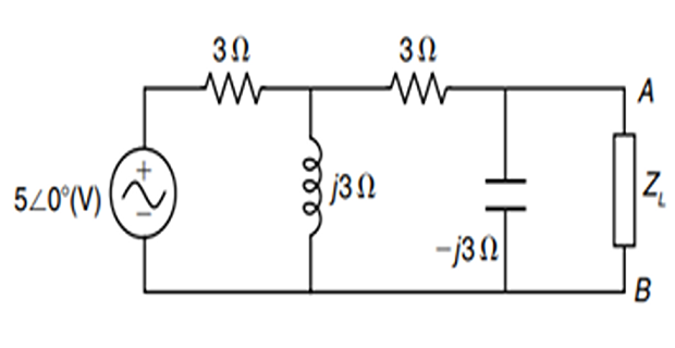
In the network shown, find the value of \(Z_L\) to which maximum power can be delivered, and hence find the value of the maximum power.
Solution
Step 1 With respect to terminals A–B, the Thevenin voltage is
\[V_{\mathrm{th}}=\frac{5 \angle 0^{\circ}}{3+\frac{j 3(3-j 3)}{3-j 3+j 3}} \times\left(\frac{j 3}{3+j 3-j 3}\right)=\frac{45 \angle 0^{\circ}}{18+j 9}=2.236 \angle-26.56^{\circ}\ (\mathrm{V})\]
Step 2 The Thevenin impedance is
\[Z_{\mathrm{th}}=\frac{\left(3+\frac{3 \times j 3}{3+j 3}\right) \times(-j 3)}{3+\frac{3 \times j 3}{3+j 3}-j 3}=3 \angle-53.12^{\circ} \Omega=(1.8-j 2.4)\ \Omega\]
Step 3 For maximum power transfer, \(Z_{L}=Z_{\text {th }}^{*}=(1.8+j 2.4)\ \Omega\) . The total impedance is then purely resistive (\(2R = 3.6\ \Omega\) ), so the current is
\[I=\frac{2.236 \angle-26.56^{\circ}}{1.8 \times 2}=0.621 \angle-26.56^{\circ}~\mathrm{A}\]
Step 4 The maximum power delivered to the load is
\[P_{\max }=\frac{\left(V_{\text {th }}\right)^{2}}{4 R}=\frac{(2.236)^{2}}{4 \times 1.8}=0.694~\mathrm{W}\]
Answer \(Z_L=(1.8+j2.4)\ \Omega,\quad P_{\max}=0.694\ \text{W}\)
Additional Practice Problems
Two fully self-contained worked examples with schematics: a frequency-domain Thevenin equivalent driving a resistive load, and a maximum-power-transfer calculation with a complex source impedance.
For the circuit below, find the Thevenin equivalent at terminals a–b and the current delivered to a \(2\ \Omega\) load. The source is \(12\angle 0^{\circ}\) V, in series with a \(4\ \Omega\) resistor, with a capacitive reactance \(-j4\ \Omega\) across the terminals.
12∠0° V
4Ω
a
−j4Ω
Rₗ
2Ω
b
Solution
Step 1 Remove the load. The open-circuit voltage is the divider across the capacitive reactance:
\[V_{Th} = 12\angle 0^{\circ}\times\frac{-j4}{4-j4} = 12\angle 0^{\circ}\times 0.7071\angle -45^{\circ} = 8.49\angle -45^{\circ}\ \text{V}\]
Step 2 Deactivating the source (short it), the impedance seen from a–b is the \(4\ \Omega\) resistor in parallel with the \(-j4\ \Omega\) reactance:
\[Z_{Th} = \frac{(4)(-j4)}{4-j4} = \frac{-j16}{4-j4} = (2-j2)\ \Omega = 2.83\angle -45^{\circ}\ \Omega\]
Step 3 Reconnecting the \(2\ \Omega\) load, the load current is:
\[I_L = \frac{V_{Th}}{Z_{Th}+R_L} = \frac{8.49\angle -45^{\circ}}{(2-j2)+2} = \frac{8.49\angle -45^{\circ}}{4.47\angle -26.57^{\circ}} = 1.90\angle -18.43^{\circ}\ \text{A}\]
Answer \(V_{Th}=8.49\angle -45^{\circ}\ \text{V},\ Z_{Th}=(2-j2)\ \Omega,\ I_L=1.90\angle -18.43^{\circ}\ \text{A}\)
A source has the Thevenin equivalent shown: \(V_{Th}=20\angle 0^{\circ}\) V in series with \(Z_{Th}=(5+j6)\ \Omega\) . Determine the load impedance \(Z_L\) that absorbs maximum average power, and find that power. (Phasor magnitudes are treated as effective values.)
Vₜₕ
20∠0°
Zₜₕ = 5+j6 Ω
a
Zₗ
b
Solution
Step 1 For maximum average power, the load must be the complex conjugate of the source impedance:
\[Z_L = Z_{Th}^{*} = (5-j6)\ \Omega\]
Step 2 With \(Z_L=Z_{Th}^{*}\) , the reactances cancel and the total impedance is purely resistive: \(Z_{Th}+Z_L = 10\ \Omega\) . The maximum power is
\[P_{\max} = \frac{|V_{Th}|^{2}}{4 R_{Th}} = \frac{(20)^{2}}{4\times 5} = 20\ \text{W}\]
Answer \(Z_L=(5-j6)\ \Omega,\quad P_{\max}=20\ \text{W}\)