Tutorial 14 — First-Order RC & RL Circuits
A first-order circuit contains a single energy-storage element (a capacitor or an inductor) and reduces to a first-order differential equation. Every response in this tutorial follows the general formula \(x(t) = x(\infty) + \big[x(0^{+}) - x(\infty)\big]\,e^{-t/\tau}\), where \(\tau = R_{Th}C\) for RC circuits and \(\tau = L/R_{Th}\) for RL circuits. These problems cover time constants, natural (source-free) responses, step responses, energy delivered or absorbed, dependent sources, and sequentially switched networks.
Part I — RC Circuits
Problems 1–10 deal with capacitive first-order circuits: time constants, source-free discharge, step (charging) responses, and energy transfer.
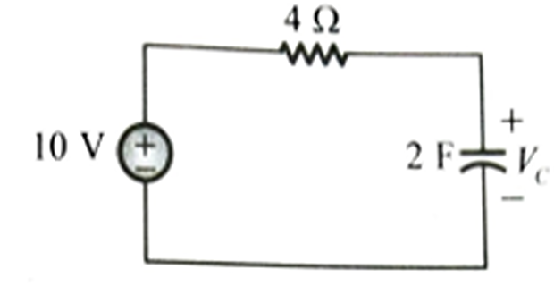
Determine the time constant of the network.
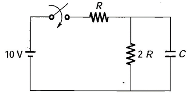
The time constant is set by the resistance seen by the capacitor. Deactivating the source (short-circuit the 10 V battery), the capacitor sees \(R\) in parallel with \(2R\):
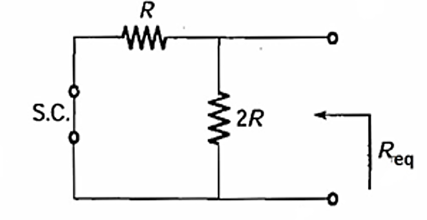
Hence the time constant:
In the circuit shown, the initial capacitor voltage is 4 V. Switch \(S_1\) is closed at \(t=0\). Find the charge lost by the capacitor from \(t = 25\ \mu s\) to \(t = 100\ \mu s\).
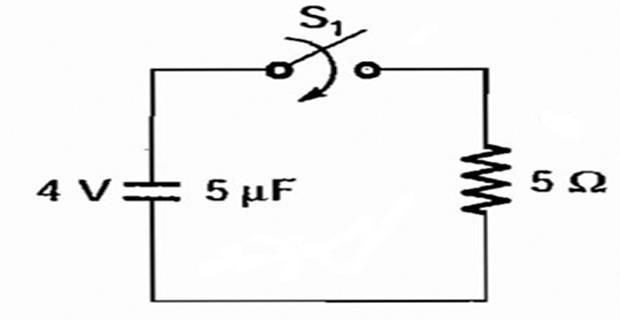
With the switch closed, the charged capacitor (\(C = 5\ \mu F\)) discharges through \(R = 5\ \Omega\). The discharge current is:
The charge lost is the integral of the current over the given interval:
\(S_1\) was closed and \(S_2\) was open for a very long time. At \(t=0\), \(S_1\) is opened and \(S_2\) is closed. Determine the voltage across the capacitor at \(t = 5\ \mu s\).
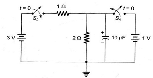
Initial value — at \(t = 0^{-}\) the capacitor was charged by the 1 V source, so:
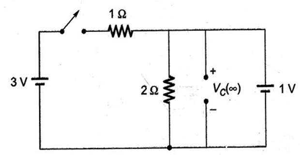
Final value — at \(t = \infty\) (capacitor open), the 3 V source divides across the 1 Ω and 2 Ω:
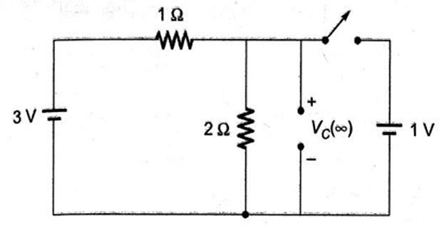
Time constant and response — the capacitor (\(C = 10\ \mu F\)) sees \(R_{Th} = 2 \parallel 1 = \tfrac{2}{3}\ \Omega\):
At \(t = 5\ \mu s\), with \(t/\tau = 0.75\):
The switch has been closed for a long time and opens at \(t=0\). Find \(v(t)\) for \(t \geq 0\).
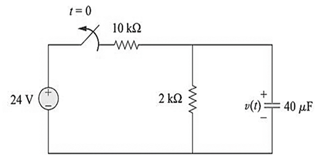
Initial value — for \(t < 0\) (switch closed, capacitor open), the source voltage divides across the 10 kΩ and 2 kΩ:
For \(t > 0\) the source is disconnected; the capacitor discharges through the 2 kΩ resistor:
For the circuit below, find \(v_o(t)\) for \(t > 0\). Determine the time necessary for the capacitor voltage to decay to one-third of its value at \(t = 0\).
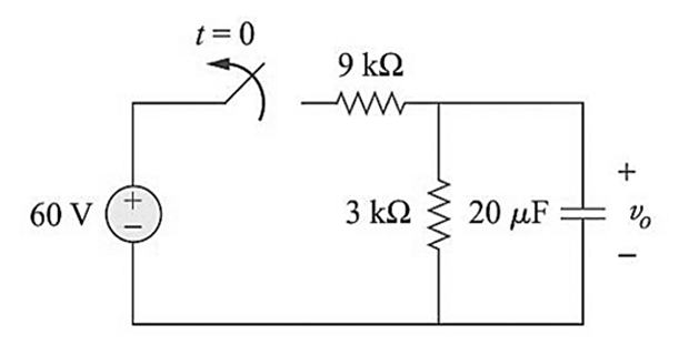
Initial value — for \(t < 0\) (switch closed, capacitor open), the 60 V source divides across the 9 kΩ and 3 kΩ:
For \(t > 0\) the source is removed, giving a source-free RC circuit with \(R = 3\ \text{k}\Omega\) and \(C = 20\ \mu F\):
Let \(t_0\) be the time at which \(v_o\) falls to one-third of its initial value. Because this ratio depends only on \(\tau\), the initial amplitude cancels:
Determine the current \(i(t)\) through the capacitor.
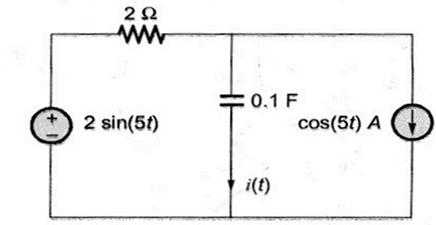
Applying source transformation, the two sources combine into a single voltage source \(2\sqrt{2}\sin(5t - 45^{\circ})\) in series with the 2 Ω resistor and 0.1 F capacitor. The series impedance at \(\omega = 5\) rad/s is:
The capacitor current is the source divided by this impedance:
The capacitor shown is initially charged to 10 V. The switch closes at \(t = 0\). Find \(v_c(t)\) at \(t = 10\) ms.
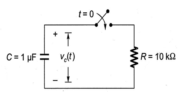
Closing the switch connects \(R = 10\ \text{k}\Omega\) across the charged capacitor (\(C = 1\ \mu F\)), producing a source-free discharge:
At \(t = 10\) ms:
The capacitor initially has a charge of 10 coulomb. Find the current in the circuit 1 second after the switch \(S\) is closed.
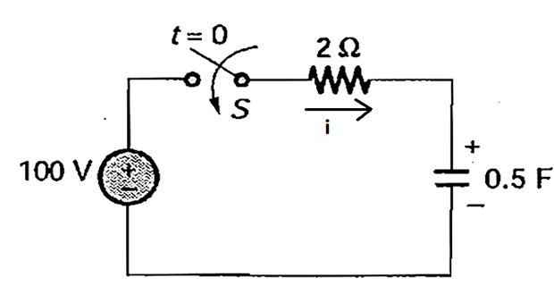
Initial and final values — the initial capacitor voltage comes from its stored charge (\(C = 0.5\ \text{F}\)), and the final value is the source voltage:
With \(\tau = RC = (2)(0.5) = 1\) s, the capacitor voltage and current are:
At \(t = 1\) s:
The initial charge on the 1 F capacitor is zero. Find the energy (in joules) transformed from the DC source until steady state is reached.
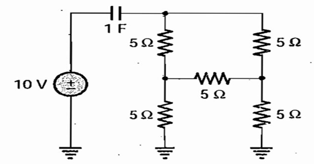
Reducing the resistor bridge by a delta–star transformation, the capacitor sees an equivalent resistance of 5 Ω in series with the 10 V source, so \(\tau = RC = (5)(1) = 5\) s. The charging current is:
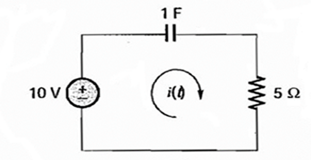
The energy supplied by the source is the integral of \(v\,i\) over all time. (Equivalently, \(E = \int V i\,dt = V\,Q_\infty = CV^{2}\), independent of \(R\).)
Find the energy absorbed by the 4 Ω resistor in the interval \((0, \infty)\). Given \(V_c(0) = 6\) V.
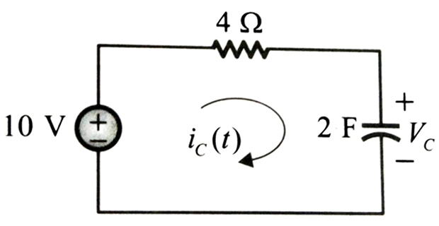
The capacitor current follows the general first-order form \(i_C(t) = i_C(\infty) + \big[i_C(0^{+}) - i_C(\infty)\big]e^{-t/\tau}\), with the given initial voltage \(V_C(0^{-}) = V_C(0^{+}) = 6\) V.
Boundary values and time constant — at \(0^{+}\) the resistor carries \((10-6)/4\); at steady state the capacitor blocks DC; and \(\tau = RC = (4)(2)\):
Substituting gives the current, and the energy is the integral of \(i_C^{2}R\):
Part II — RL Circuits
Problems 11–14 deal with inductive first-order circuits, where the time constant is \(\tau = L/R_{Th}\) and the inductor current cannot change instantaneously.
Assuming that \(i(0) = 10\) A, calculate \(i(t)\) and \(i_x(t)\).
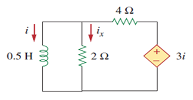
Method 1 — because of the dependent source, apply a 1 V test source \(v_o\) at the inductor terminals and solve the mesh equations:
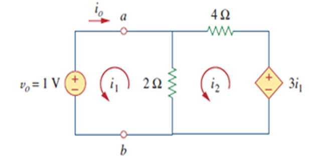
Hence the Thevenin resistance, time constant and natural response:
Method 2 — alternatively, write the circuit's differential equation directly:
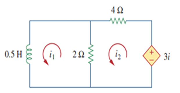
Finally, the inductor voltage gives \(i_x\) through the 2 Ω resistor:
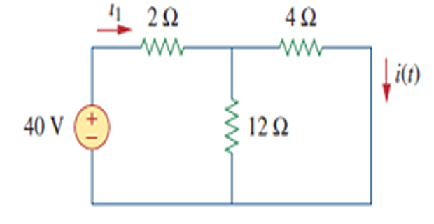
The switch has been closed for a long time. At \(t = 0\) the switch is opened. Calculate \(i(t)\) for \(t > 0\).
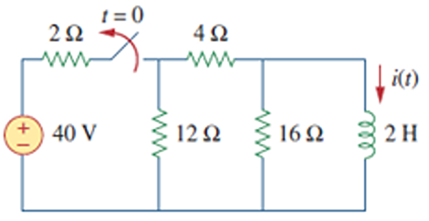
Initial value — for \(t < 0\) the switch is closed, the inductor acts as a short, and the 16 Ω resistor is shorted out:
For \(t > 0\) the source is disconnected; the inductor current starts at \(i(0^{+}) = i(0^{-}) = 6\) A and decays through the remaining resistance:
Find \(i_o\), \(v_o\) and \(i\) for all time, assuming the switch was open for a long time.
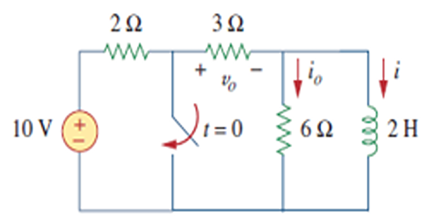
For \(t < 0\) the switch is open, the inductor is a short, and the 6 Ω resistor is shorted:
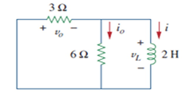
For \(t > 0\) the source-free network has \(R_{Th} = 3 \parallel 6 = 2\ \Omega\), giving:
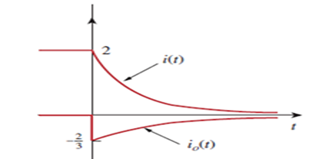
The 6 Ω current follows from the inductor voltage, and assembling all intervals:
At \(t = 0\), switch-1 is closed, and switch-2 is closed 4 s later. Find \(i(t)\) for \(t > 0\), and calculate \(i\) at \(t = 2\) s and \(t = 5\) s.
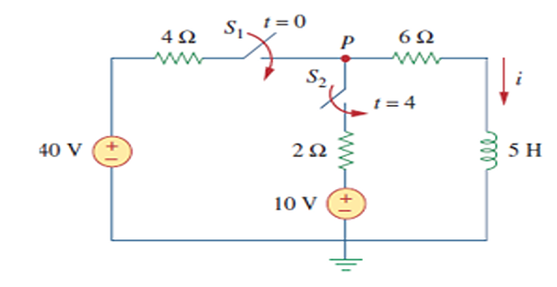
Analyse the three intervals \(t \leq 0\), \(0 \leq t \leq 4\), and \(t \geq 4\) separately. For \(t < 0\) both switches are open, so:
For \(0 \leq t \leq 4\), \(S_1\) is closed (with \(S_2\) still open), so the 4 Ω and 6 Ω are in series. Assuming \(S_1\) stays closed:
Hence over this interval:
For \(t \geq 4\), \(S_2\) closes and connects the 10 V source through the 2 Ω. Since inductor current is continuous, the new initial value is:
To find the new steady state, let \(v\) be the node voltage at P and apply KCL:
The Thevenin resistance at the inductor terminals and the new time constant:
Shifting the exponential by the 4 s delay:
Putting all intervals together:
Evaluating at the requested times:
Additional Practice Problems
Two self-contained worked examples with schematics, illustrating the step (energizing) response that complements the source-free and switching cases above: an RC circuit charging from zero and an RL circuit building up current from zero.
A 12 V source charges an initially uncharged 50 µF capacitor through a 4 kΩ resistor. The switch closes at \(t = 0\). Find \(v_c(t)\) for \(t \geq 0\) and the time to reach 90% of the final voltage.
The capacitor starts uncharged and charges toward the source voltage, so the boundary values and time constant are:
Applying the general first-order formula:
The time to reach \(0.9\times12 = 10.8\) V:
A 24 V source energizes a 2 H inductor through an 8 Ω resistor. The inductor current is zero before the switch closes at \(t = 0\). Find \(i(t)\) for \(t \geq 0\) and the voltage across the inductor.
The inductor current starts at zero and builds toward its DC steady-state value \(V/R\); the time constant is \(L/R\):
Applying the general first-order formula:
The inductor voltage follows from \(v_L = L\,di/dt\):