Learning Outcomes
- Use the per-phase equivalent circuit of the IM to derive air-gap power, torque, and maximum torque expressions.
- Explain why maintaining a constant \(V_s/f_s\) ratio preserves rated torque capability across the entire speed range.
- Sketch the V/f voltage command profile, identifying the constant-torque region, the low-speed IR-boost, and the field-weakening region.
- Describe the closed-loop slip-speed control scheme and state how it improves upon open-loop V/f.
- Explain constant air-gap flux control and compare it with simple V/f control in terms of accuracy and complexity.
- Apply the V/f design equations to a given motor specification.
Per-Phase Equivalent Circuit of the Induction Motor
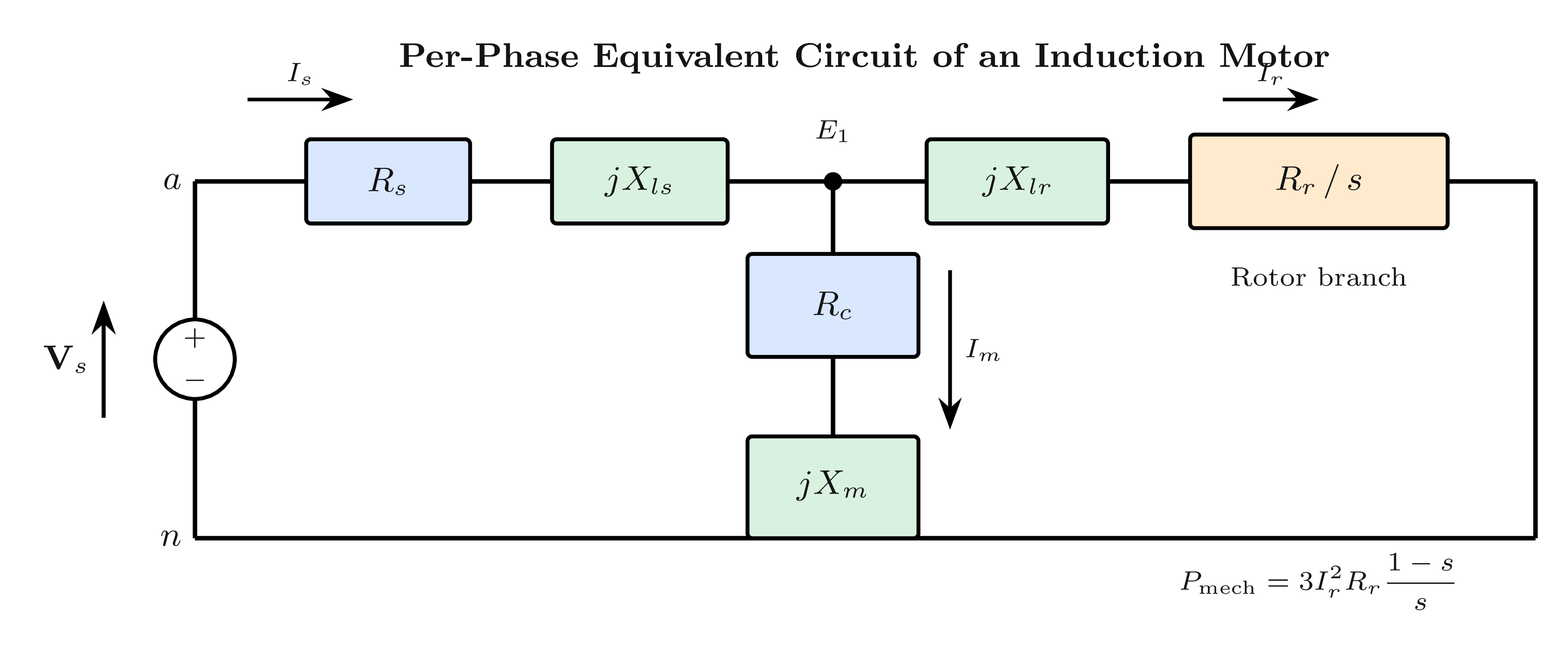
- \(R_r/s\) is the total referred rotor resistance; mechanical power is extracted from \(R_r(1-s)/s\)
- \(R_c\) represents core (iron) losses; often omitted in drive analysis for simplicity
- This circuit is valid for the fundamental frequency only — harmonics require separate circuits (see Lecture 7D)
- The stator voltage \(V_s\) drives current through the stator impedance (\(R_s + jX_{ls}\)) and the parallel combination of the magnetising branch and rotor branch
Power & Torque Relations
Power Flow Relations
where \(\omega_{s,mech} = 4\pi f_s / P\) is the synchronous mechanical speed.
Electromagnetic Torque (exact expression)
Valid when stator resistance and leakage are neglected (\(E_1 \approx V_s\)). The air-gap EMF \(E_1\) is the voltage across the magnetising branch.
Maximum (Breakdown) Torque
The slip at maximum torque \(s_{T_{max}}\) is independent of stator voltage — only rotor parameters matter.
Key Relationship: Air-Gap Flux and Maximum Torque
Keeping the air-gap flux linkage \(\lambda_m = \text{const}\) is equivalent to keeping \(|E_1|/\omega_s = \text{const}\). This ensures rated torque capability at every speed. Neglecting stator impedance: \(E_1 \approx V_s\), so \(V_s/f_s = \text{const}\) achieves this approximately.
Constant Volts-per-Hertz (V/f) Control
- Air-gap flux linkage: \(\lambda_m \propto E_1/\omega_s\)
- Neglecting stator impedance drop: \(E_1 \approx V_s\)
- Keeping \(V_s/f_s = \text{const} \;\Rightarrow\; \lambda_m = \text{const} \;\Rightarrow\; \text{rated torque at all speeds}\)
- Without this: flux collapses at low speed → weak motor, very poor torque production
V/f Voltage Command (peak phase voltage)
where \(K_{vf} = \hat{V}_{ph,rated}/f_{rated}\) is the V/Hz slope and \(V_o \approx I_{rated}\,R_s\) is the low-speed IR-drop boost voltage.
Without \(V_o\): the stator resistance drop at low frequencies consumes a large fraction of \(V_s\), leaving insufficient voltage across the magnetising branch → flux collapses → torque drops to near zero at low speeds.
Relationship Between \(V_{dc}\) and Rated Phase Voltage
For the six-step VSI: \(\hat{V}_{as,1} = \dfrac{2}{\pi}V_{dc} \approx 0.637\,V_{dc}\). Therefore:
For a PWM-VSI, the DC bus voltage must be at least this value. In practice, a diode rectifier from the AC supply provides a fixed \(V_{dc}\), and PWM adjusts the effective output voltage.
V/f Operating Profile: Constant Torque and Field-Weakening Regions
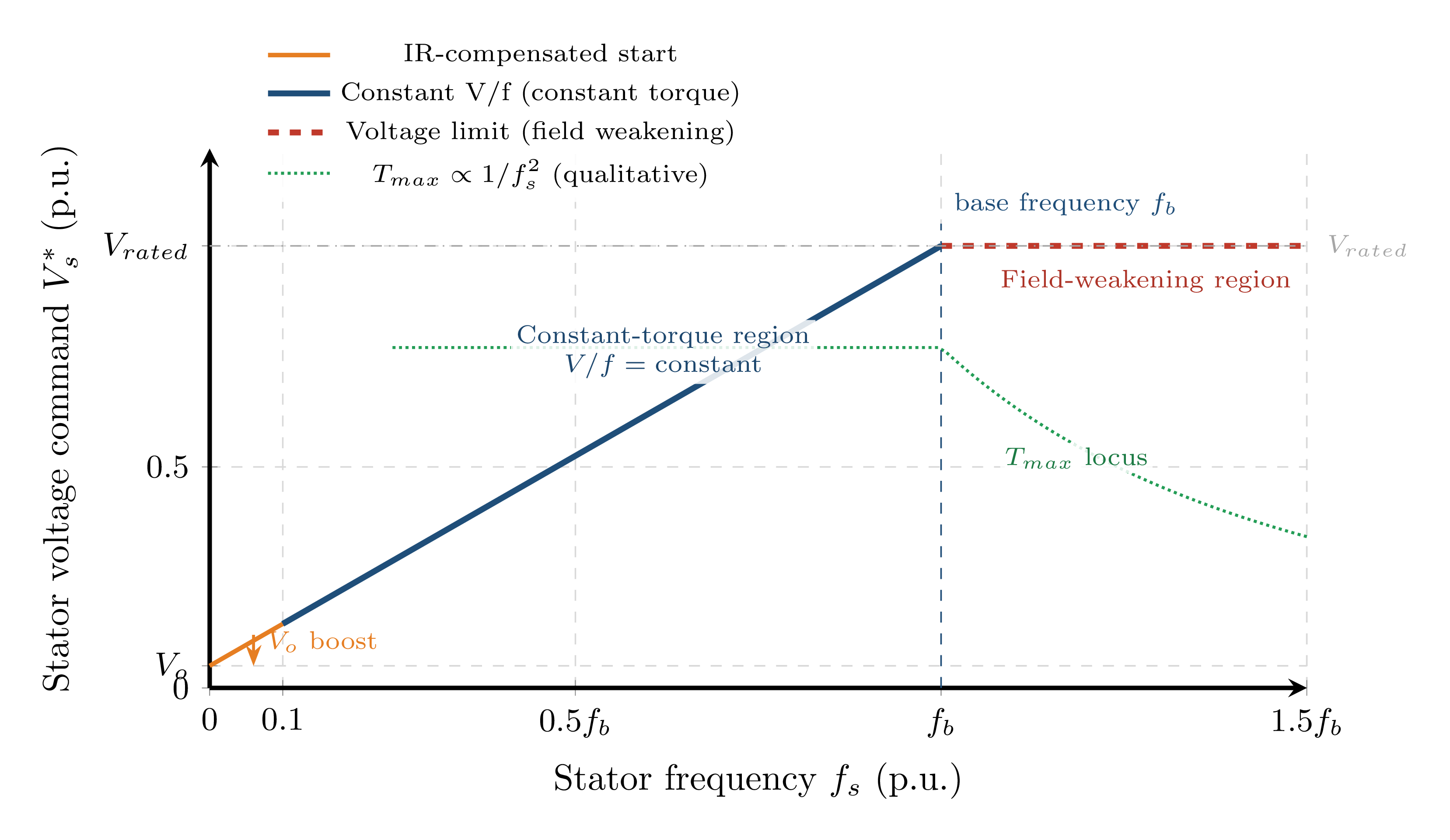
Region 1: Below Base Frequency \(f_b\) — Constant Torque
- \(V_s/f_s = K_{vf}\) (constant slope)
- \(\lambda_m = \text{const}\)
- \(T_{max} = \text{const}\) (constant torque capability)
- Low-speed boost \(V_o\) applied to compensate \(R_s\) drop
Region 2: Above \(f_b\) — Field Weakening (Constant Power)
- \(V_s = V_{rated}\) (voltage clamped at rated value)
- \(\lambda_m \propto 1/f_s\) (flux decreasing)
- \(T_{max} \propto 1/f_s^2\) (torque capability falls)
- Constant-power region: \(P = T_e \cdot \omega_r \approx \text{const}\) if \(T_e \propto 1/\omega_r\)
Closed-Loop V/f: Constant Slip-Speed Control
- Pure V/f has no speed feedback
- Speed regulation error of ±2–5% under load variation
- At sudden load increase: motor slows but inverter frequency stays fixed → slip grows uncontrolled
- Risk of exceeding breakdown torque → stalling
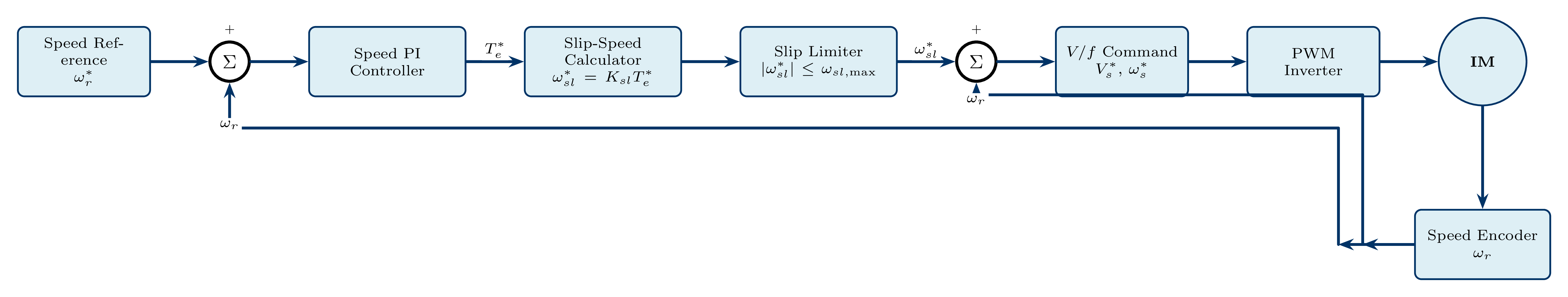
Frequency Synthesis
\(\omega_{sl}^*\) is limited to \(\omega_{sl,max} = R_r/L_{lr}\) to prevent stalling. The speed measurement \(\omega_r\) comes from a shaft encoder or speed observer.
Improvements over Open-Loop V/f
- Speed regulation improved to <1%
- Faster dynamic response to load transients
- Slip limiter prevents breakdown and stalling
- Better low-speed torque capability
- Still scalar — flux and torque not independently regulated
Constant Air-Gap Flux Control
- Fixed V/f ignores the stator impedance drop \(\mathbf{I}_s(R_s + jX_{ls})\)
- At low frequencies this drop is significant relative to \(V_s\); air-gap flux is not truly constant
- Air-gap EMF from KVL: \(E_1 = V_s - I_s(R_s + jX_{ls})\)
- Solution: measure \(I_s\) in real time and compensate the voltage command accordingly
Constant-\(\lambda_m\) Voltage Command
Desired air-gap EMF: \(E_1^* = \lambda_m^*\,\omega_s\)
More accurate than fixed \(V_o\) boost, especially at very low speeds (\(f_s < 5\) Hz). Requires real-time current measurement each PWM cycle.
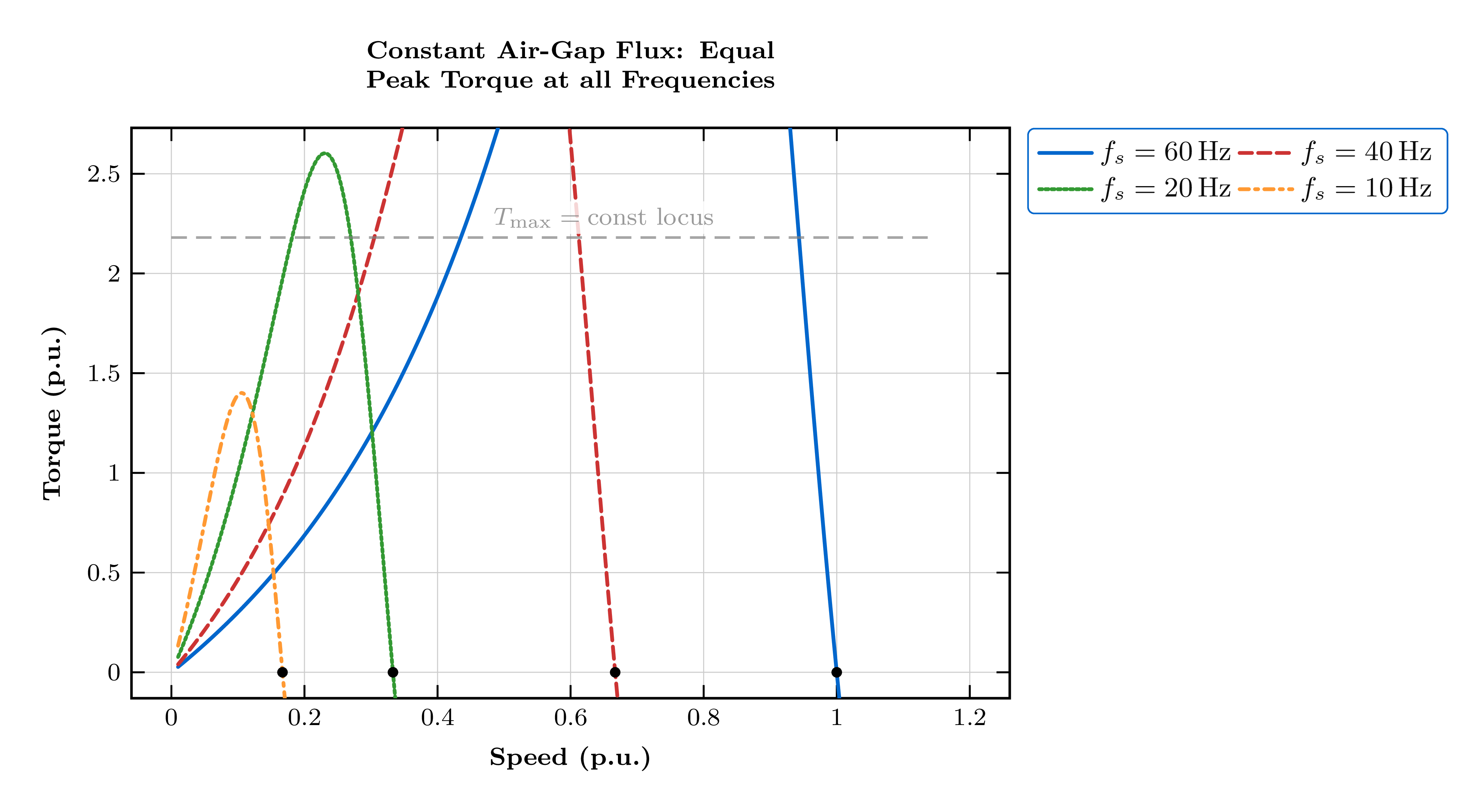
With Constant Air-Gap Flux Control
Peak torque is nearly equal at all frequencies, providing excellent speed range and low-speed torque. This constant-flux scalar strategy leads naturally to Field-Oriented Control (FOC), which achieves full decoupling of the flux and torque channels and is covered in Chapter 8.
Comparison of Scalar V/f Control Strategies
| Feature | Const. V/Hz | Const. Slip Speed | Const. \(\lambda_m\) |
|---|---|---|---|
| Speed feedback | None | Speed sensor | \(V_s\) and \(I_s\) sensors |
| Speed accuracy | Low (±2–5%) | Medium (<1%) | High |
| Flux control | Approximate | Approximate | Exact (real-time compensation) |
| Low-speed torque | Poor | Better | Best |
| Complexity | Low | Medium | High |
| Cost | Lowest | Medium | Higher |
| Best application | Fans, pumps | General purpose | High performance |
Limitation of All Scalar Methods
All scalar (V/f) methods regulate magnitude only — flux and torque cannot be independently controlled. Dynamic torque-step response is slow (typically >50 ms). For fast dynamics, use Field-Oriented Control (FOC) or Direct Torque Control (DTC) — covered in Chapter 8.
Design Example: V/f Drive for a 5 hp Motor
Given Motor Parameters
5 hp, 200 V (L-L), 60 Hz, 3-phase, 4-pole
\(R_s = 0.277\,\Omega\), \(X_{ls} = 0.554\,\Omega\), \(X_m = 20.3\,\Omega\), \(R_r = 0.183\,\Omega\), \(X_{lr} = 0.841\,\Omega\)
Step 1: V/f Constant (peak phase basis)
Step 2: Low-speed boost voltage
Step 3: Maximum allowable slip speed
Step 4: DC bus voltage at rated output
Step 5: Slip at maximum torque
Design Summary
\(K_{vf} = 2.72\) V/Hz | \(V_o = 7.7\) V | \(V_{dc} = 256\) V | \(\omega_{sl,max} = 82\) rad/s | \(s_{T_{max}} = 0.22\)