Learning Outcomes
- Describe the ASCI drive system and explain how the DC-link inductor enforces constant \(I_{dc}\).
- Trace the four-stage commutation sequence for the ASCI and derive the capacitor sizing criterion.
- Sketch the quasi-square (120°) stator phase current waveform and state its Fourier series.
- Derive the electromagnetic torque and maximum torque for a CSI-fed IM and explain why \(T_{max}\) is frequency-independent for the CSI.
- Explain how natural regeneration is achieved in the CSI by phase-angle reversal of the rectifier.
- Describe the closed-loop speed-control structure of the ASCI drive and identify the role of each loop.
CSI Drive Configuration
System Building Blocks
- Controlled rectifier: three-phase thyristor bridge; sets \(V_r\) and hence \(I_{dc}\)
- DC-link inductor \(L_f\): large inductor (tens of mH) that forces a nearly constant DC current — the current source
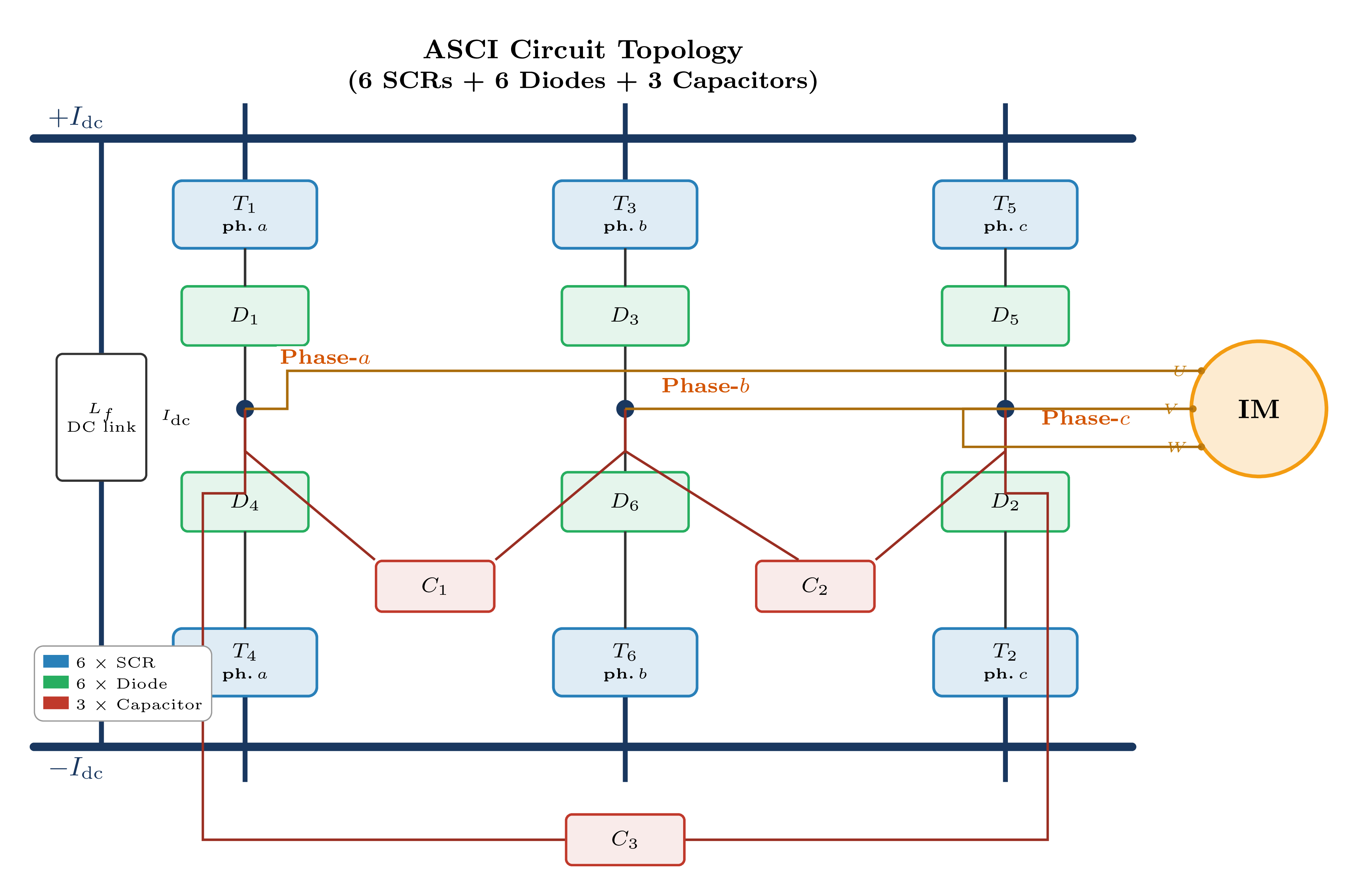
- ASCI inverter: six SCRs with auxiliary commutation capacitors; distributes \(I_{dc}\) among motor phases in sequence
- Induction motor: operates as a current-fed machine; terminal voltage is determined by motor impedance
DC-Link Behaviour
Governing Equation of the DC Link
\(V_r\) = rectifier output voltage (controlled by firing angle \(\alpha\)); \(V_i\) = inverter input voltage (average motor terminal voltage). The large \(L_f\) makes \(dI_{dc}/dt\) small, so \(I_{dc}\) is nearly constant — analogous to the large \(C_f\) maintaining constant \(V_{dc}\) in a VSI.
Key Properties of the DC Link:
- The direction of \(I_{dc}\) is always positive (fixed by \(L_f\))
- Power direction is reversed by reversing \(V_r\) (set \(\alpha > 90°\) → inverting operation)
- Short-circuit on the motor side is safe: \(L_f\) limits \(di/dt\)
- Open-circuit on the motor side is dangerous: the inductor generates a large \(L_f\,di/dt\) voltage spike — the motor must never be disconnected under load
VSI (Voltage-Source Inverter)
- Output is a voltage; motor current is free to take any shape
- DC-link element: capacitor \(C_f\) → stiff voltage source
- Short circuit on output: catastrophic
- Open circuit on output: safe
CSI (Current-Source Inverter)
- Output is a current; motor voltage is determined by motor impedance
- DC-link element: inductor \(L_f\) → stiff current source
- Short circuit on output: safe (\(L_f\) limits \(di/dt\))
- Open circuit on output: dangerous (inductive spike)
Motor Voltage Contains Ringing
Because the CSI switches a constant current into inductive motor windings, the commutation of the CSI causes an \(LC\) resonance between the commutation capacitors and the motor leakage inductance. This produces voltage spikes at the motor terminals. The motor insulation must be rated for the peak voltage, not merely the fundamental RMS value. Typically a margin of 1.5–2× the fundamental peak is required.
ASCI Commutation Mechanism
Inverter Components:
- Six main SCRs: \(T_1\)–\(T_6\) — gated in sequence, 60° apart
- Six freewheeling diodes: \(D_1\)–\(D_6\) — one in series with each SCR; prevent reversal of SCR current and block the motor's back-EMF from the DC link
- Three commutation capacitors: \(C_1\), \(C_2\), \(C_3\) — one connected between each pair of adjacent output lines; store charge to force-commutate outgoing SCR
- At any instant, exactly two SCRs conduct simultaneously; each SCR conducts for 120°
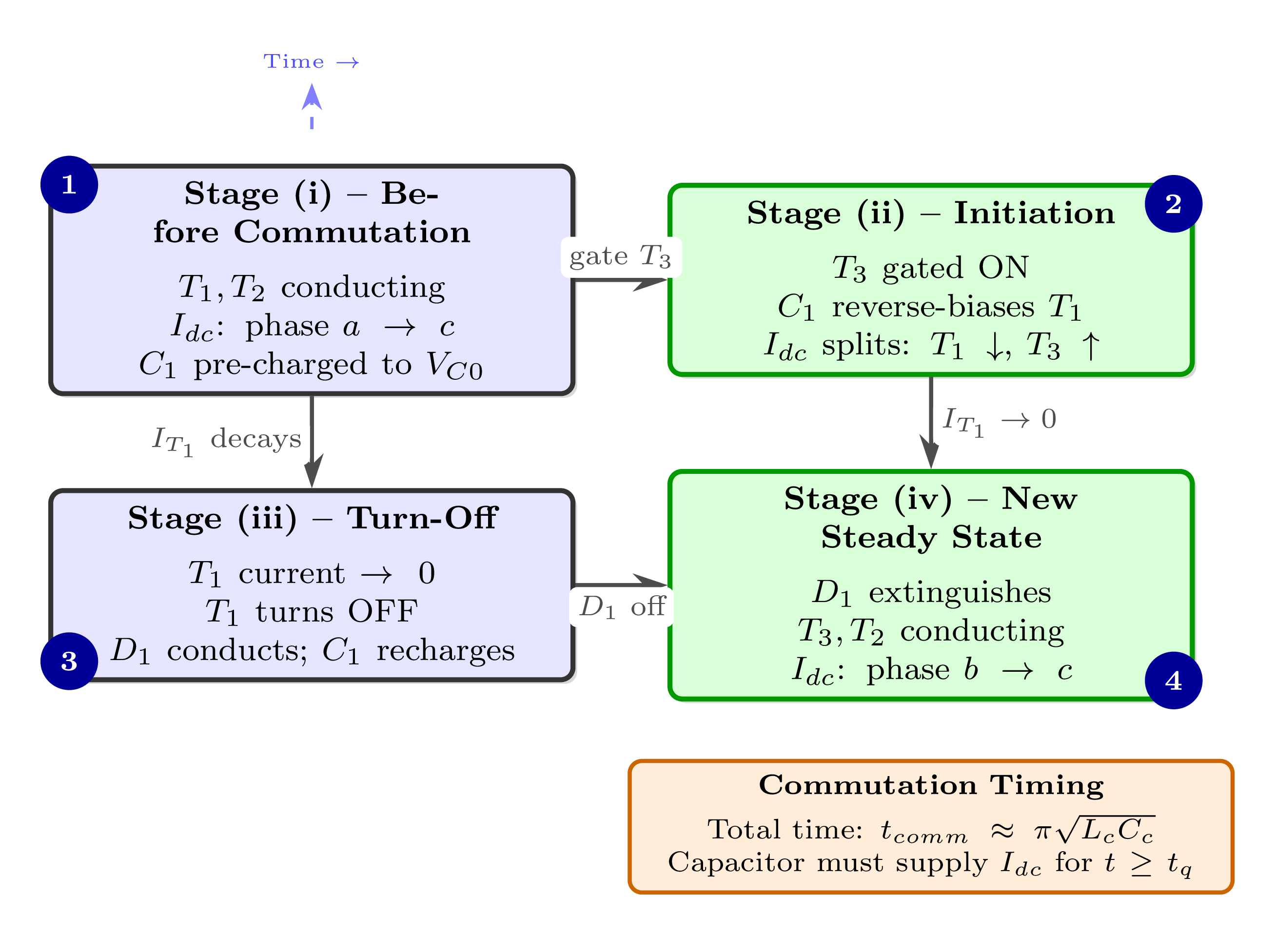
Stage (i): Initial Steady State
\(T_1\) and \(T_2\) are ON; \(I_{dc}\) flows from the DC link through \(T_1\) into phase \(a\), and returns via phase \(c\) through \(T_2\). Commutation capacitor \(C_1\) (connected between phases \(a\) and \(b\)) is pre-charged to voltage \(V_{C0}\), ready for the next commutation.
Stage (ii): Commutation Initiated
\(T_3\) is gated ON. The pre-charged capacitor \(C_1\) immediately applies a reverse voltage across \(T_1\), reducing its current. \(I_{dc}\) now splits: a decreasing portion through \(T_1\) and an increasing portion through \(T_3\) (via the resonant \(LC\) path through \(C_1\) and the motor leakage inductance).
Stage (iii): SCR Turn-Off
\(T_1\) current falls to zero and stays reverse-biased for at least the SCR turn-off time \(t_q\). \(T_1\) then turns OFF. The freewheeling diode \(D_3\) associated with phase \(b\) begins to conduct, and the capacitor \(C_1\) recharges in the opposite polarity, ready for the next commutation event.
Stage (iv): New Steady State
\(T_3\) and \(T_2\) are ON; \(I_{dc}\) now flows through phase \(b\) into phase \(c\). The commutation is complete. \(C_1\) is left charged to \(-V_{C0}\) for the subsequent commutation (when \(T_5\) is to replace \(T_3\)).
Commutation Capacitor Sizing
Physical Requirement
The commutation capacitor must supply enough charge to hold the outgoing SCR reverse-biased for at least the minimum turn-off time \(t_q\) specified in the SCR datasheet. If the reverse bias period is shorter, the SCR will re-fire (commutation failure).
Minimum Capacitance
\(I_{dc}\) = DC link current (A); \(t_q\) = SCR circuit-commutated turn-off time (μs, from datasheet); \(V_{C0}\) = initial capacitor voltage at the start of commutation (V). The capacitor voltage \(V_{C0}\) is approximately equal to the motor line-to-line voltage at the time of commutation.
Voltage Spike at Motor Terminals
\(L_{\sigma s}\) = stator transient leakage inductance. The sudden current step \(\Delta I_{dc}\) through \(L_{\sigma s}\) during commutation generates a voltage spike at the motor terminals. Mitigation: snubber capacitors (typically 5–20 μF) connected across the motor terminals reduce the peak \(dv/dt\) and limit the spike magnitude.
Output Current Waveforms
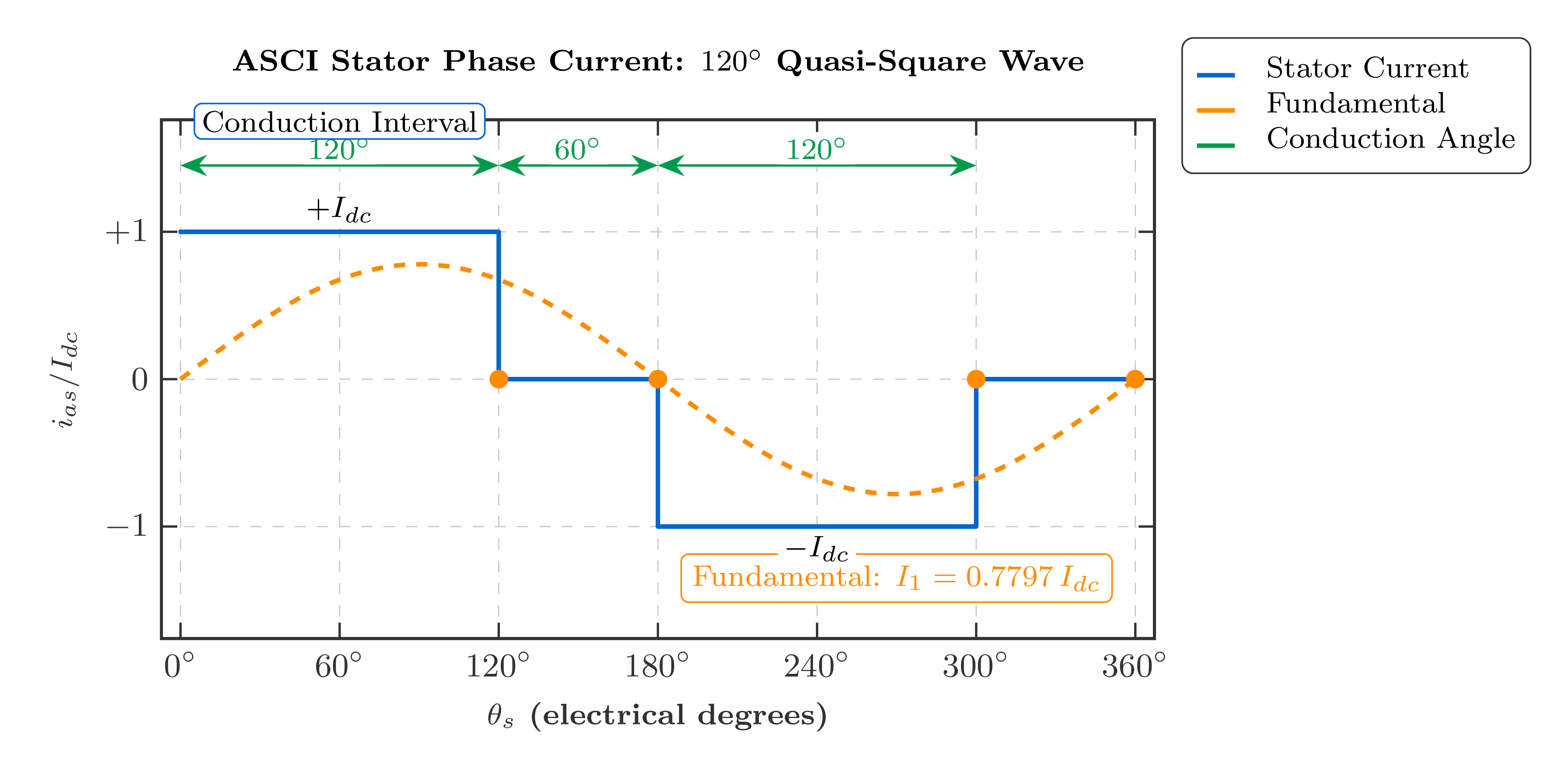
Waveform Description
Each phase current is a quasi-square wave with the following pattern per fundamental cycle:
- \(+I_{dc}\) for 120°
- Zero for 60°
- \(-I_{dc}\) for 120°
- Zero for 60°
This 120° conduction waveform is the dual of the VSI's 180° (six-step) voltage waveform.
Fundamental RMS Current
This is the RMS value of the fundamental frequency component of the stator phase current.
Fourier Expansion
Due to the half-wave and one-third symmetry of the quasi-square waveform, only harmonics of order \(n = 6k \pm 1\) (\(k = 0, 1, 2, \ldots\)) are present — the same set as in the VSI six-step voltage.
The harmonic magnitudes decay as \(I_n = I_{s1}/n\), so the 5th harmonic is 20% of the fundamental, the 7th is 14.3%, and so on.
| Harmonic order \(n\) | \(I_n / I_{s1}\) | Sequence | Effect on motor |
|---|---|---|---|
| 1 | 1.000 | Positive | Useful torque production |
| 5 | 0.200 | Negative | Backward rotating MMF; parasitic braking torque; extra rotor heating |
| 7 | 0.143 | Positive | High-slip forward torque; ripple at \(6\omega_s\) with 5th |
| 11 | 0.091 | Negative | Additional copper and core losses |
| 13 | 0.077 | Positive | Torque ripple at \(12\omega_s\) with 11th |
Current THD of the ASCI
This is higher than a well-designed PWM-VSI drive (<5% THD) but comparable to the six-step VSI. The motor should be derated by approximately 10–15% to account for additional harmonic losses.
Motor Torque Equations
Torque Expression (Fundamental Component)
Using the per-phase equivalent circuit with a current source feeding the motor, the electromagnetic torque per phase can be written as:
\(I_s\) = stator phase current (fundamental RMS); \(L_m\) = magnetising inductance; \(L_r = L_{lr}+L_m\) = total rotor inductance; \(L_\sigma = L_s - L_m^2/L_r\) = stator transient inductance; \(s\) = slip; \(\omega_s\) = stator electrical angular frequency.
Maximum (Breakdown) Torque
Differentiating \(T_e\) with respect to slip and setting to zero gives the slip at maximum torque and the maximum torque:
\(L_\sigma = L_s - L_m^2/L_r\) is the stator transient leakage inductance. Critically, \(T_{e,max}\) depends only on \(I_s\) and machine parameters — it is independent of frequency \(\omega_s\).
VSI (Voltage-Source Drive)
- Maximum torque decreases as frequency increases
- In the field-weakening region (\(f > f_b\)), \(V_s\) is fixed, so \(T_{max} \propto 1/\omega_s^2\)
- Requires V/f control to maintain flux and hence torque capability
CSI (Current-Source Drive)
- Maximum torque is frequency independent
- Peak torque is maintained at any speed by keeping \(I_{dc}\) constant
- Excellent constant-torque characteristic over the full speed range
- No equivalent of field weakening unless \(I_{dc}\) is deliberately reduced
Harmonic Current Content
Additional Losses Due to Harmonic Currents:
- Extra stator copper loss: \(\Delta P_{cu,s} = 3\sum_{n>1} I_n^2\,R_s\)
- Extra rotor copper loss: \(\Delta P_{cu,r} = 3\sum_{n>1} I_n^2\,R_r\) (since \(s_n \approx 1\) for high-order harmonics)
- Core losses: eddy-current losses scale as \(n^2\); hysteresis losses scale as \(n\)
- Total additional heating: approximately 10–25% above fundamental-only operation
Torque Ripple:
- 5th (negative-sequence) + 7th (positive-sequence) → torque ripple at \(6\omega_s\)
- 11th + 13th → torque ripple at \(12\omega_s\)
- Causes audible noise, mechanical vibration, and increased bearing and gear wear
Remedy: PWM-CSI
Replacing SCRs with self-commutating devices (GTO or IGBT with series diode) and applying PWM control shifts harmonics to high frequencies, dramatically reducing torque ripple and motor derating. This is covered in Lecture 7G.
Regenerative Operation
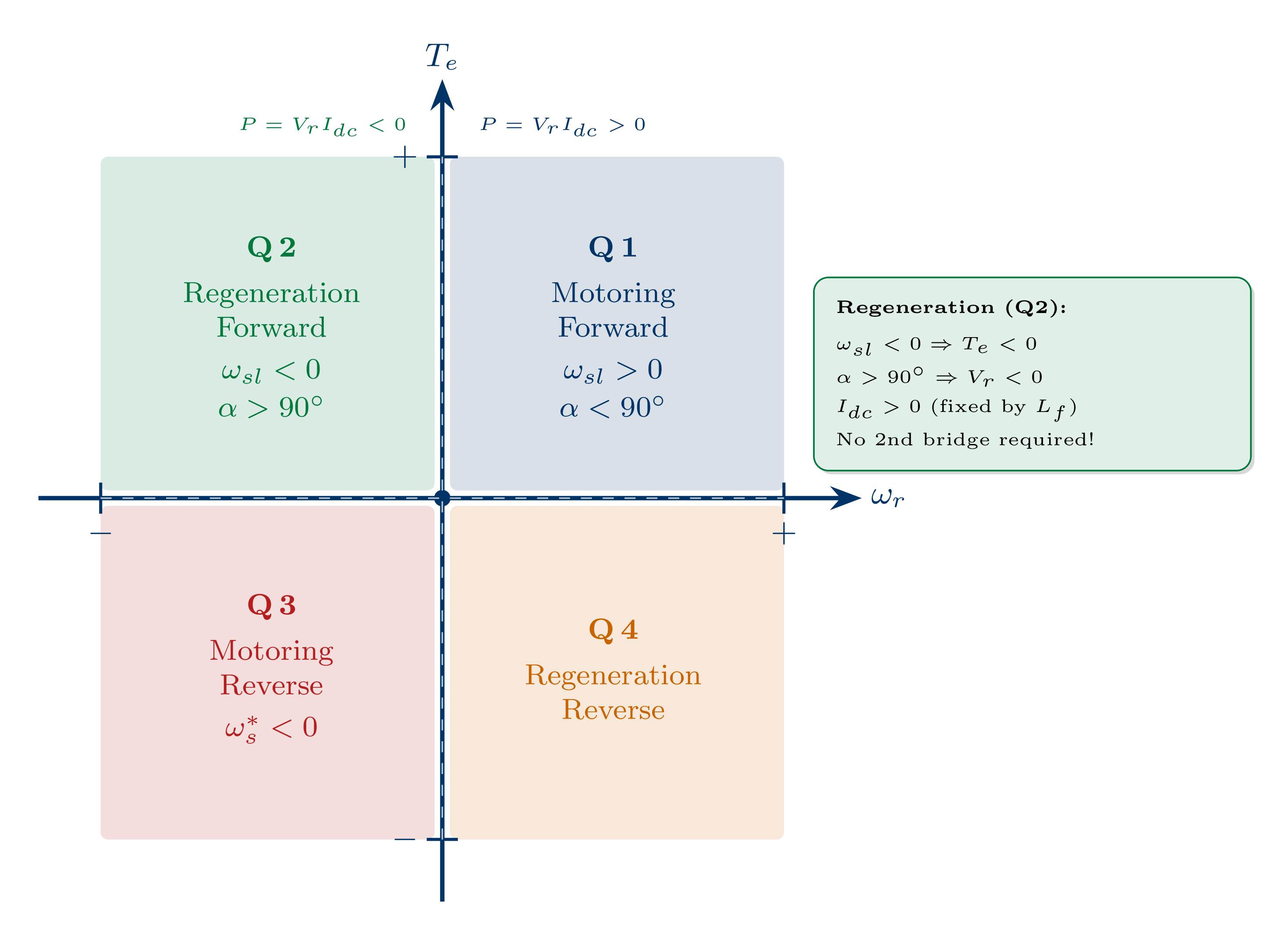
Motoring Mode (Q1)
- Positive slip: \(\omega_{sl} = \omega_s - \omega_r > 0\)
- Rectifier firing angle: \(\alpha < 90°\) → \(V_r > 0\)
- Power flow: grid → motor (\(P = V_r\,I_{dc} > 0\))
Regenerating Mode (Q2)
- Reduce inverter frequency \(\omega_s\) below \(\omega_r\): slip becomes negative, \(\omega_{sl} < 0\)
- Motor acts as an induction generator: inverter input voltage \(V_i\) reverses polarity
- Set \(\alpha > 90°\) → rectifier operates in inverting mode: \(V_r < 0\)
- \(I_{dc}\) remains positive (enforced by \(L_f\))
- Power flow: \(P = V_r\,I_{dc} < 0\) → energy returned to the AC grid
- No second converter bridge is required
Reverse Motoring (Q3)
Reverse the phase sequence of the ASCI gating signals (set \(\omega_s^* < 0\)). The motor runs in the reverse direction at forward-sense current.
| Quadrant | \(\omega_r\) | \(T_e\) | \(V_r\) | \(\alpha\) | Description |
|---|---|---|---|---|---|
| Q1 | \(+\) | \(+\) | \(+\) | \(<90°\) | Forward motoring |
| Q2 | \(+\) | \(-\) | \(-\) | \(>90°\) | Forward regenerating (induction generator) |
| Q3 | \(-\) | \(-\) | \(+\) | \(<90°\) | Reverse motoring (phase-sequence reversal) |
| Q4 | \(-\) | \(+\) | \(-\) | \(>90°\) | Reverse regenerating |
Regeneration Advantage over VSI
A standard diode-rectifier VSI cannot regenerate — braking energy must be dissipated in a braking resistor. The CSI's thyristor rectifier naturally accommodates regeneration by operating in the inverting mode, returning kinetic energy to the supply without any additional hardware.
Closed-Loop Speed Control
Outer Speed Loop
- Input: speed error \(\omega_r^* - \omega_r\)
- Controller: PI with anti-windup
- Output: torque command \(T_e^*\), which is then converted to a slip-speed command \(\omega_{sl}^* = K_{sl}\,T_e^*\)
- Slip limiter: \(|\omega_{sl}^*| \le R_r/L_{lr}\) prevents operation beyond the breakdown torque point
Frequency Synthesis
The inverter frequency command \(\omega_s^*\) is formed by adding the measured rotor speed \(\omega_r\) (from a tachometer or encoder) and the commanded slip speed \(\omega_{sl}^*\). This ensures the inverter frequency tracks the rotor speed, keeping the motor on the stable portion of the torque-speed curve.
Inner DC-Current Loop
- Input: current error \(I_{dc}^* - I_{dc}\)
- Controller: PI with anti-windup
- Output: rectifier firing angle \(\alpha\)
- This loop is 5–10× faster in bandwidth than the outer speed loop to ensure cascade stability
- Typical inner loop bandwidth: 50–200 Hz; outer speed loop: 5–20 Hz
Minimum Copper-Loss (Optimal Flux) Current Command
Rather than keeping \(I_{dc}\) fixed, a common strategy selects the DC current that minimises total stator and rotor copper losses at the commanded slip speed. At light loads (small \(\omega_{sl}^*\)), the optimal \(I_{dc}^*\) is reduced, lowering flux and hence losses. At full load, \(I_{dc}^*\) recovers to the rated value.
\(I_m\) = rated magnetising current. This expression selects the optimal trade-off between rotor flux level and rotor copper loss at each operating point.
VSI vs. CSI Comparison
| Feature | VSI | CSI |
|---|---|---|
| DC-link element | Capacitor \(C_f\) | Inductor \(L_f\) |
| Controlled quantity | Voltage | Current |
| Short-circuit on output | Dangerous | Safe (\(L_f\) limits \(di/dt\)) |
| Open-circuit on output | Safe | Dangerous (spike) |
| Motor voltage | Controlled (PWM) | Determined by motor impedance |
| Motor voltage spikes | Low (with PWM) | Present (commutation ringing) |
| Regeneration | Requires AFE or braking resistor | Natural (one converter) |
| \(T_{max}\) vs. frequency | \(\propto 1/\omega_s^2\) (field weakening) | Frequency independent |
| Typical power range | \(< 2\) MW | 100 kW – several MW |
| Motor current THD | <5% (PWM-VSI) | ~31% (ASCI); <5% (PWM-CSI) |
| Motor insulation stress | Moderate | High (voltage spikes) |
Where the ASCI Drive Excels
- High-power applications (500 kW to several MW) where the cost of commutation components is small relative to the converter rating
- Applications requiring natural four-quadrant regenerative braking without additional converter hardware
- Mine hoists, rolling mills, large ship propulsion, large compressors
- Applications where a robust, simple control structure is preferred over high dynamic performance
Where the ASCI Drive Is Not Preferred
- Low-power applications (<100 kW): VSI is simpler and cheaper
- Applications requiring very smooth motor currents: use PWM-CSI or PWM-VSI
- High-speed or wide-speed-range operation: the commutation capacitor must be re-sized for different frequency ranges
- Applications where audible noise is critical: the quasi-square current causes significant noise