Learning Outcomes
- State the relationship between supply frequency and synchronous speed, and explain why a variable-frequency supply enables variable-speed operation.
- Quantify the energy-saving potential of variable-frequency drives on fan and pump loads using the Affinity Laws.
- Classify static frequency changers into direct and indirect types, and identify their key sub-types.
- Describe the operating principle and output-frequency limitation of the cycloconverter.
- Compare VSI and CSI drive topologies with respect to DC-link element, power range, and regenerative capability.
Why Frequency Control? The Induction Motor Speed Problem
Why the Induction Motor Dominates Industry
- Rugged, brushless, low-maintenance, and low cost
- Available in power ratings from a few watts to megawatts
- When connected directly to the 50/60 Hz grid, speed is essentially fixed
Synchronous Speed
where \(f_s\) = supply frequency (Hz) and \(P\) = number of poles.
The actual rotor speed is related to synchronous speed through the slip \(s\):
Full-load slip \(s \approx 1\)–5%, so the rotor runs just below synchronous speed.
Key Insight: Variable-Frequency Drive
Since \(n_s \propto f_s\), varying the supply frequency shifts the entire torque–speed curve:
A static frequency changer (power converter) makes this possible without mechanical gearing or rotor resistance losses.
Affinity Laws & Energy-Saving Potential
- Pre-electronics: Rotor-resistance injection (lossy), pole changing (discrete steps only)
- 1970s: Thyristor (SCR) converters → early AC drives
- 1980s: GTO devices → high-power drives; eliminated bulky commutation capacitors
- 1990s–2000s: IGBTs + DSP → modern VFD revolution; switching frequencies up to 20 kHz
- Today: Over 90% of new industrial variable-speed drives are AC VFDs; SiC/GaN devices enable even higher efficiency
Centrifugal fans, pumps, and compressors obey the Affinity Laws:
where \(n\) is the shaft speed. The cubic relationship between power and speed is the key result.
Energy Savings Calculation
Reducing speed by just 20% (i.e., running at 80% speed):
VFDs typically save 20–50% of motor energy in fan and pump applications. This is the primary economic driver for VFD adoption in HVAC and water treatment.
Why Not Throttle Valves or Dampers?
Traditional flow control by partly closing a valve or damper wastes energy as heat. The pump or fan still operates near full power while restricting output. A VFD reduces the speed instead — matching power consumption to the actual load requirement.
Torque–Speed Characteristics Under Variable Frequency
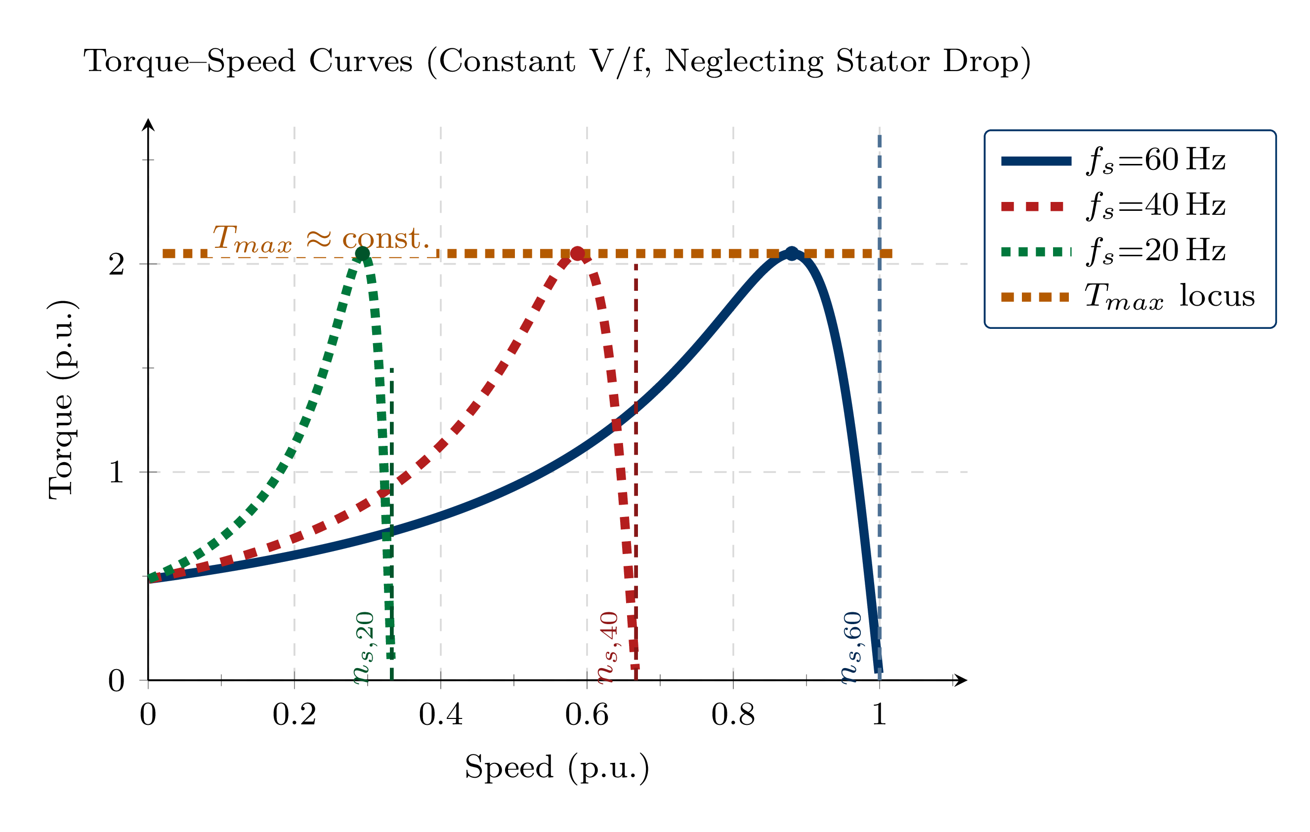
- Synchronous speed scales linearly with frequency: \(n_s \propto f_s\)
- Reducing \(f_s\) shifts the entire T–ω curve to the left
- Speed can be varied continuously from 0 to rated (and beyond for field weakening)
- Stable region: low slip, left of the breakdown-torque point
- Breakdown torque locus: the envelope of peak torque points is maintained constant when \(V_s/f_s = \text{const}\)
Constant V/f Principle
To keep air-gap flux — and hence breakdown torque — constant as frequency is varied, the terminal voltage must be scaled proportionally: \(V_s / f_s = \text{constant}\). This is called constant volts-per-hertz (V/f) control and is discussed in detail in Lecture 7C.
Variable-Frequency Drive: Advantages & Applications
| Benefit | Detail |
|---|---|
| Smooth speed control | 0 to 100%+ speed range; infinitely variable |
| High starting torque | Even at very low speeds without excessive current |
| Soft-start capability | Eliminates high inrush current; reduces mechanical stress |
| Regenerative braking | With bidirectional front-end (AFE, CSI, or dual thyristor bridge) |
| Energy savings | Fans/pumps: \(P \propto \omega^3\); 20–50% savings typical |
| Precise process control | Closed-loop speed and torque regulation |
Regeneration Caveat
True 4-quadrant operation requires a bidirectional front-end: an Active Front-End (AFE) VSI, an anti-parallel thyristor bridge, or a CSI drive. A standard diode-rectifier + PWM-VSI drive dissipates braking energy in a braking resistor unless an AFE is fitted.
- HVAC: Fans, pumps, compressors, chillers — the largest application segment
- Material handling: Conveyors, hoists, cranes, escalators
- Manufacturing: Machine tools, CNC axes, robotic joints
- Heavy industry: Paper mills, steel rolling mills, extruders
- Infrastructure: Water and wastewater treatment plants
- Traction: Electric vehicles and railway drives
Classification of Static Frequency Changers
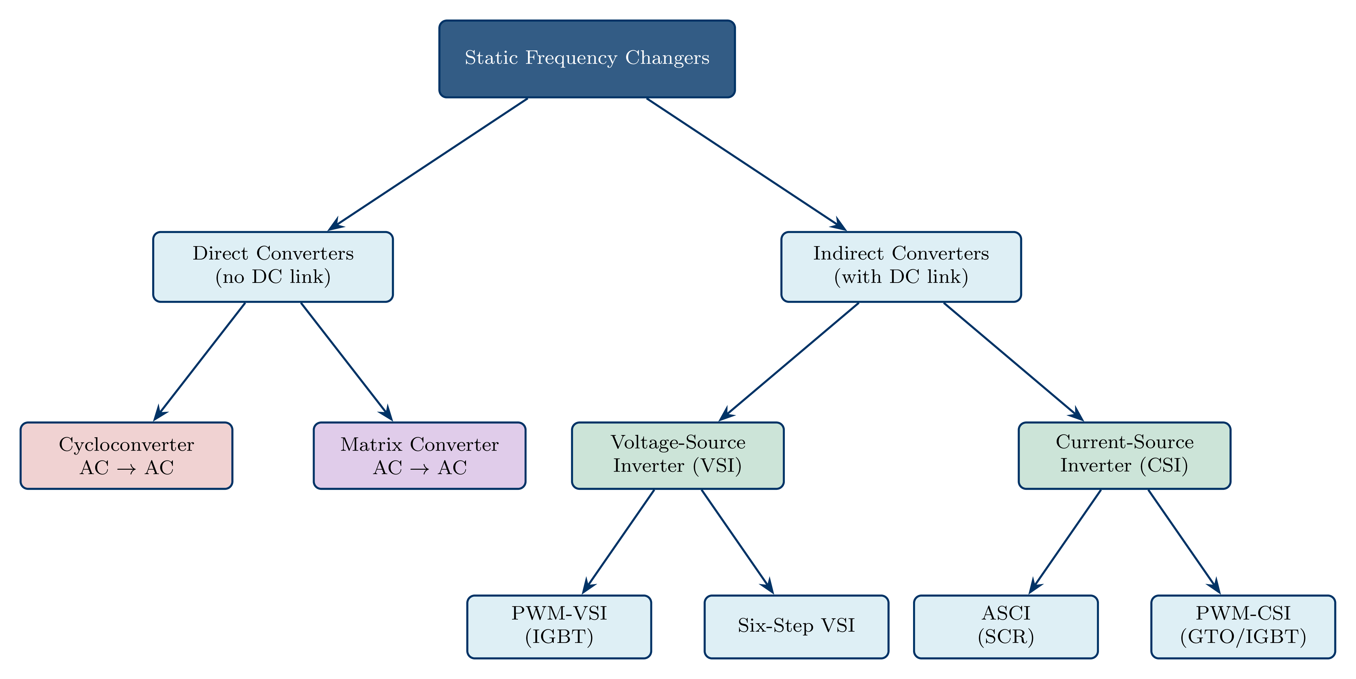
Direct Converters (AC → AC, no DC stage):
- No DC-link capacitor or inductor; power transferred directly
- Cycloconverter: Output frequency limited to \(f_{out} \leq \tfrac{1}{3}f_{in}\)
- Matrix converter: 0 to \(f_{in}\); self-commutating; no DC link
Indirect Converters (AC → DC → AC):
- A DC link decouples the rectifier from the inverter
- VSI (Voltage-Source Inverter): Capacitor \(C_f\) maintains constant \(V_{dc}\)
- CSI (Current-Source Inverter): Inductor \(L_f\) maintains constant \(I_{dc}\)
| Type | Typical Power Range | Remarks |
|---|---|---|
| VSI (IGBT-PWM) | Up to 2 MW | Most common; standard for general-purpose drives |
| CSI | 100 kW – several MW | High-power; natural regeneration; thyristor or IGBT |
| Cycloconverter | Several MW (multi-MW) | \(f_{out} < 20\) Hz; gearless low-speed drives |
| Matrix Converter | Emerging; kW – MW | Compact; unity PF; no DC capacitor; limited adoption |
Direct Converter: Cycloconverter
- Converts 3-phase AC directly to variable-frequency, variable-voltage 3-phase AC — no intermediate DC stage
- Anti-parallel SCR bridge groups: positive group (P) for positive load current; negative group (N) for negative load current
- Output voltage synthesised from segments of input sine waves by phase-angle control (\(\alpha\))
- Output frequency limit: \(f_{out} \leq \tfrac{1}{3}f_s\) to maintain acceptable waveform quality
- No self-commutation; relies on natural (line) commutation of SCRs
| Property | Value / Comment |
|---|---|
| Output frequency range | 0 to \(0.33\,f_s\) (typically 0–20 Hz on 60 Hz supply) |
| Power range | Very high — MW to tens of MW |
| SCR count (3-phase out) | 18–36 per drive (6 per output phase, P and N groups) |
| Input power factor | Lagging; poor at low \(V_{out}\) |
| Regeneration | Natural — inherent four-quadrant capability |
| Applications | Ball mills, cement kilns, ship propulsion, rolling mills, gearless mine hoists |
Best Use Case
Cycloconverters excel in very-low-speed, very-high-torque gearless drives, e.g., ball mill ring motors (<10 rpm, tens of MW). The absence of a DC link and mechanical gearbox greatly improves reliability. Practical limit: \(f_{out} \leq 20\) Hz for a 60 Hz supply.
Direct Converter: Matrix Converter
- A \(3 \times 3\) array of bidirectional switches directly connects any input phase to any output phase at any instant
- No DC energy storage — no bulk capacitors or inductors; very compact and lightweight
- PWM algorithms simultaneously synthesise the desired output voltage and shape the sinusoidal input current
- Output frequency: 0 to \(f_{in}\) — not limited like the cycloconverter
- Inherently bidirectional power flow; four-quadrant operation without extra hardware
Key Limitation
Maximum output voltage is limited to 86.6% of the input voltage — a fundamental consequence of Venturini's theorem. This voltage transfer ratio cannot be exceeded without over-modulation, making the matrix converter less attractive for drives that need the full bus voltage.
| Feature | Cycloconverter | Matrix Converter |
|---|---|---|
| Self-commutated | No (line-commutated SCRs) | Yes (bidirectional IGBT switches) |
| Max. output frequency | \(\leq \tfrac{1}{3}f_s\) | 0 to \(f_s\) |
| Max. output voltage | \(V_{in}\) (full) | \(0.866\,V_{in}\) (87%) |
| Input power factor | Lagging (poor at low output) | Near unity (controllable) |
| DC storage | None | None |
| Switch count (3-phase) | 18–36 SCRs | 9 bidirectional (18 IGBTs + 18 diodes) |
| Maturity | Mature, MW-range commercial | Emerging; some MW drives available |
Indirect DC-Link Converters: VSI Drive Types
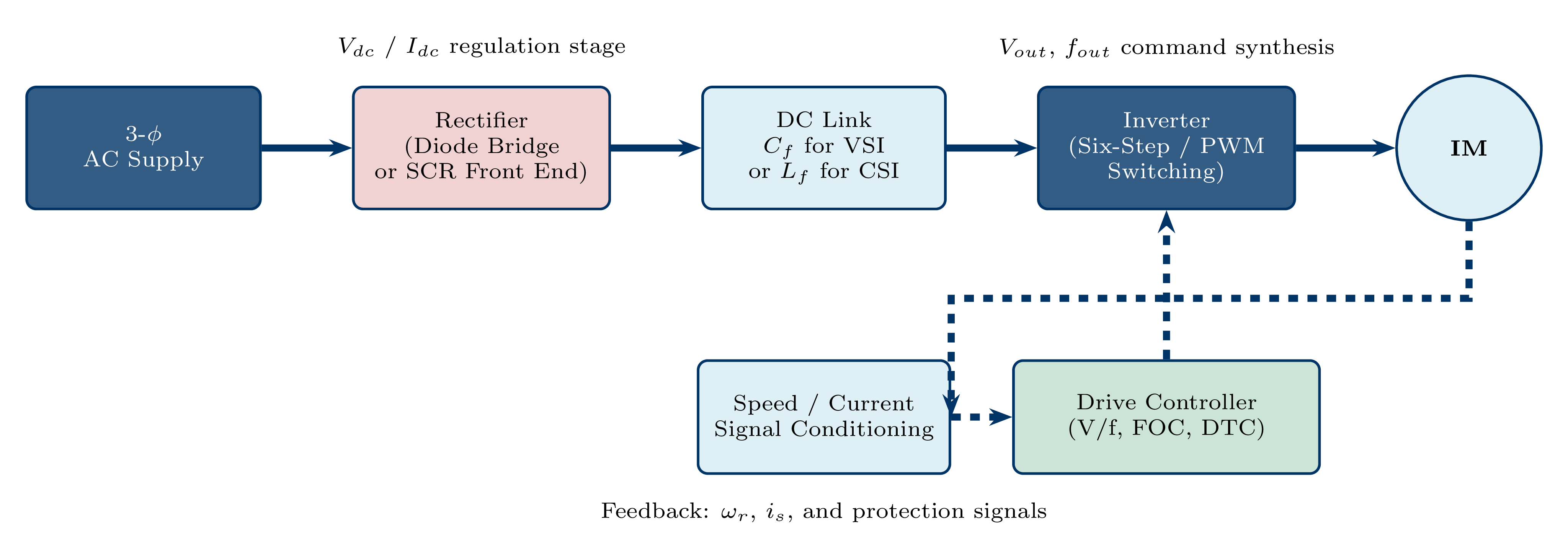
(i) Diode Rectifier + PWM-VSI (most common)
- Uncontrolled diode rectifier → fixed \(V_{dc} \approx \sqrt{2}\,V_{LL}\)
- Voltage and frequency both controlled in the inverter via PWM
- Near-unity displacement PF at input; no natural regeneration
(ii) Controlled Rectifier + Six-Step VSI
- Thyristor phase-controlled rectifier → variable \(V_{dc}\); inverter sets frequency
- Input power factor degrades at light load
- Regeneration possible with anti-parallel thyristor bridge
(iii) Active Front-End (AFE) + PWM-VSI
- Both stages use IGBT bridges with PWM control
- Bidirectional power flow; near-unity PF at all loads; very low input THD
- Preferred for regenerative elevator, crane, and renewable applications
CSI Drive Topology & VSI vs. CSI Comparison
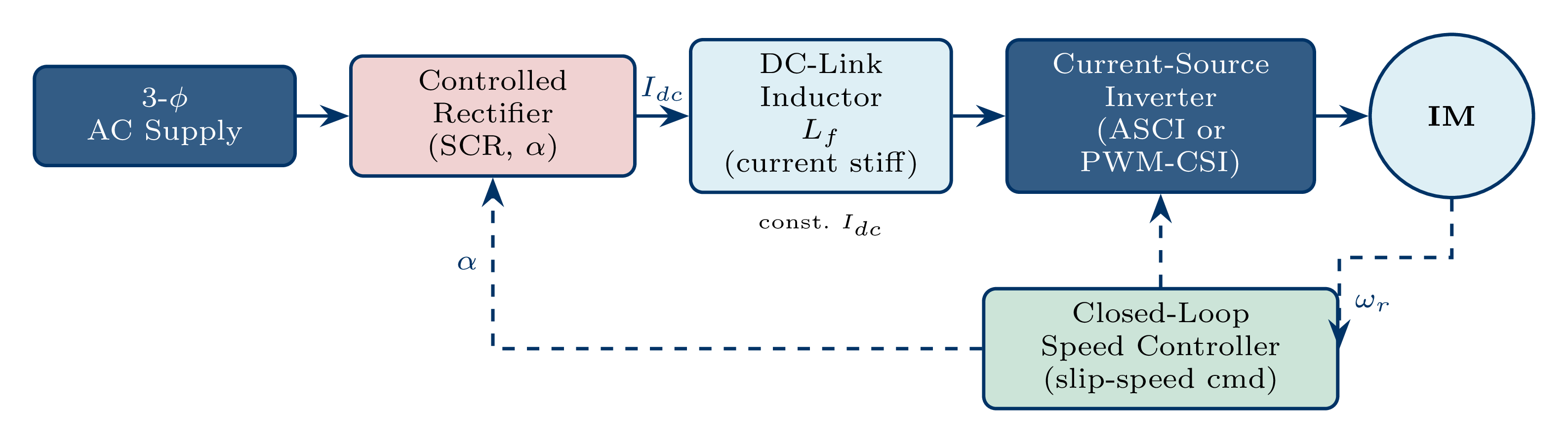
| Feature | VSI | CSI |
|---|---|---|
| DC-link element | \(C_f\) (capacitor) | \(L_f\) (inductor) |
| Controlled quantity | Voltage | Current |
| Short-circuit safe | Dangerous | Safe (\(L_f\) limits \(di/dt\)) |
| Open-circuit safe | Safe | Dangerous (must have load) |
| Regeneration | Requires 2nd bridge or AFE | Natural (one converter) |
| Typical power | <2 MW | 100 kW – several MW |
| Lecture | Topic |
|---|---|
| 7b | VSI circuit and six-step operation |
| 7c | VSI-fed IM: steady-state performance and V/f control |
| 7d | Harmonic analysis and dynamic modelling (qdo frame) |
| 7e | PWM strategies: SPWM, SHE, SVM, and carrier scheduling |
| 7f | CSI drives: ASCI circuit and operation |
| 7g | CSI dynamics, PWM-CSI, and chapter summary |