Demonstrative Video
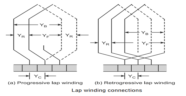
Lap Winding
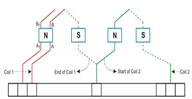
Consecutive coils overlap each other.
The first end of the winding is connected to the one segment of the commutator, and the starting end of the other coil is placed under the same magnet (different pole) and join with the same segment of the commutator.
The conductors are connected in such a way that the number of parallel paths equals to the number of poles.

Consider the machine has P poles and Z armature conductors, then there will be P parallel paths, and each path will have Z/P conductors in series.
The number of brushes is equivalent to the number of parallel paths.
The half of the brush is positive, and the remaining is negative.
Classification of Lap Winding
Simplex Lap Winding
number of parallel path between the brushes is equal to the number of poles
Duplex Lap Winding
number of the parallel paths between the brushes is twice the number of poles

\(Y_B = Y_F \pm 2m\)
\(m\) multiplicity of the winding
\(m=1\) for Simplex Lap winding
\(m=2\) for Duplex Lap winding

Progressive winding: \(Y_B > Y_F\)
Retrogressive winding: \(Y_B < Y_F\)
The back pitch and front pitch must be odd.
Resultant pitch (\(Y_R\)) = \(Y_B – Y_F\) = \(2m\) ; even
Average pitch \(\left(Y_{A}\right)=\frac{Y_{B}+Y_{F}}{2}=\text { pole-pitch }\left(Y_{P}\right)=\frac{Z}{P}\)
Back pitch \(\left(Y_{B}\right) \approx \frac{Z}{P}\)
Commutator pitch \(Y_c = \pm m\)
Number of parallel path in the Lap winding = \(mP\)

Equalizer Ring
In Lap winding, the EMF’s induced in each parallel path may not be exactly equal.
results in internal circulating currents in the armature circuit and in the brushes.
Causes : Excessive heating, sparking at the brushes and mechanical vibration
To overcome this, Equaliser rings are provided at the back of the armature
Function of equalizer rings is to avoid unequal distribution of current at the brushes thereby helping to get sparkless commutation
No of equaliser rings, \(m = \dfrac{Z}{2P}\)
-
Required for large current applications because it has more parallel paths.
Suitable for low voltage and high current generators.
Disadvantages of lap windings
It gives less emf compared to wave winding.
Requires more no. of conductors for giving the same emf, which results in high winding cost.
It has less efficient utilization of space in the armature slots.
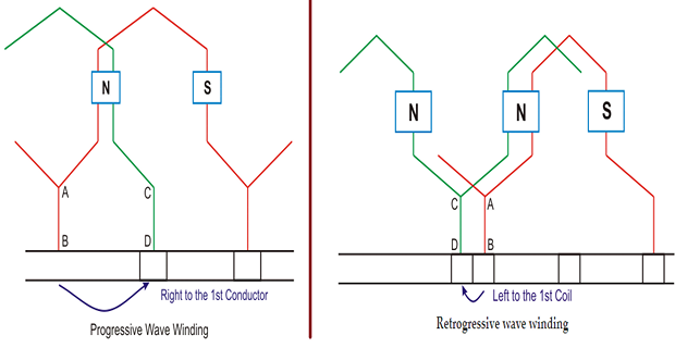
Wave Winding
One end of the coil is connected to the starting end of the other coil which has the same polarity as that of the first coil.
Coils are connected in wave shape, hence wave winding.
Conductor of the wave winding are split into two parallel paths, and each path had Z/2 conductors in series.
Number of brushes = 2, i.e., the number of parallel paths.
-
If after one round of the armature the coil falls in a slot right to its starting slot the winging
Retrogressive wave winding:
If after one round of the armature the coil falls in a slot left to its starting slot the winging

\(Y_B\) and \(Y_F\) are nearly equal to \(Y_P\) and maybe equal or differ by \(\pm2\). + for progressive winding, – for retrogressive winding.
Resultant pitch \(Y_R = Y_B + Y_F\)
Commutator pitch (\(Y_C\)) = average pitch (\(Y_A\))
Average pitch \(Y_A\) = \(\dfrac{Y_B+Y_F}{2}\) = \(\dfrac{Z \pm 2}{P}\)
Since \(Y_A\) must be an integer, this winding is not possible with any no. of conductors.
- Let us take 8 conductors in a 4 pole machine.\[\text { Then, } Y_{A}=\frac{Z \pm 2}{P}=\frac{8 \pm 2}{4}=\frac{10}{4}=2 \frac{1}{2} \text { or } 3 \frac{1}{2}\]
Being fractional no the wave winding is no possible but if there was 6 conductors then the winding can be done.
- Since,\[Y_{A}=\frac{Z \pm 2}{P}=\frac{6 \pm 2}{4}=\frac{8}{4}=2=\text { an integer. }\]
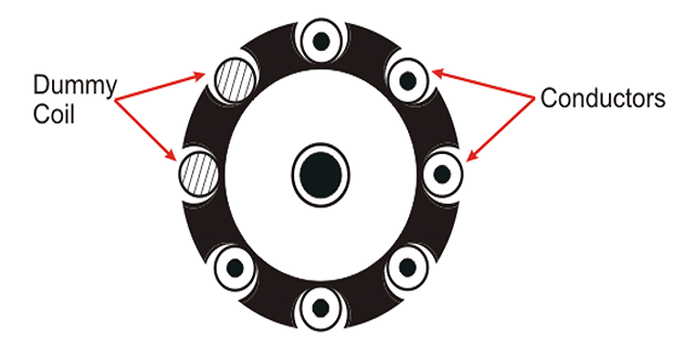
For this problem the DUMMY COILS are introduced.
Dummy Coils
The wave winding is possible only with a particular number of conductors and slot combinations.
It is not always possible to have the standard stampings in the winding shop consist of the number of slots according to the design requirements.
In such cases, dummy coils are employed.
These dummy coils are placed in the slots to give the machine the mechanical balance but they are not electrically connected to the rest of the winding.
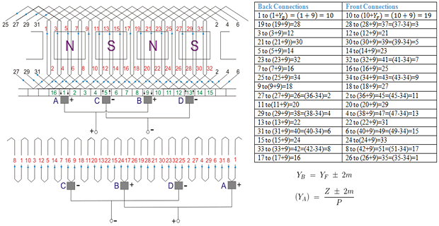
simplex progressive wave winding diagram having 34 conductors in 17 slots and 4 poles.
Only two brushes are required but more parallel brushes can be added to make it equal to the no. of poles.
If one or more brushes set poor contacts with the commutator, satisfactory operation is still possible.
Gives sparkles commutation because it has two parallel paths irrespective of the number of poles of the machine.
For a given \(P\) and \(Z\), it gives more emf than that of lap winding. Hence wave winding is used in high voltage and low current machines. This winding is suitable for small generators circuit with a voltage rating of \(500-600 \mathrm{~V}\).
Disadvantages of Simplex Wave winding
cannot be used in machines having higher current rating because it has only two parallel paths.
Comparison between Lap and Wave Winding

