Demonstrative Video
Introduction to AC Motors
Universal adoption of ac system of distribution of electrical energy for light and power, the field of application of ac motors has widened considerably
As regard to the principle of operation ac motors can be classified into
Synchronous Motors
Asynchronous Motors (or Induction Motors)
Induction motor can be squirrel cage or slip-ring (external resistance)
Induction Motors: General Principle
As a general rule, conversion of electrical power into mechanical power takes place in the rotating part of an electric motor
In dc motors, the electric power is conducted directly to the armature (i.e. rotating part) through brushes and commutator
Hence, dc motor can be called a conduction motor
However, in ac motors, the rotor does not receive electric power by conduction but by induction in exactly the same way as a 2-winding TF receives its power from the primary
Thus, such motors are known as induction motors
In fact, an IM can be treated as a rotating transformer, primary winding is stationary but the secondary is free to rotate
Of all the ac motors, the polyphase IM is the one which is extensively used for various kinds of industrial drives.
Advantages and Disadvantages
ADVANTAGES:
Simple and extremely rugged, almost unbreakable construction (especially squirrel cage type)
Cost is low and reliable
Sufficiently high efficiency. In normal running condition no brushes are needed, hence frictional losses are reduced. It has a reasonably good power factor.
Requires minimum maintenance
It starts from rest and needs no extra starting motor and has not to be synchronized.
Starting arrangement is simple especially for the squirrel cage type
DISADVANTAGES:
Its speed cannot be varied without sacrificing some of its efficiency
Just like a dc shunt motor, its speed decreases with increase in load
Its starting torque is somewhat inferior to that of a dc shunt motor
Applications
1-\(\Phi\) Induction Motor
Low power and domestic applications
Pumps
Compressors
Small fans
Mixers
Toys
High speed vacuum cleaners
Electric Shavers
Drilling machines
3-\(\Phi\) Induction Motor
Industrial and commercial applications
Lifts
Cranes
Hoists
Large capacity exhaust fans
Driving lathe machines
Crushers
Oil extracting mills
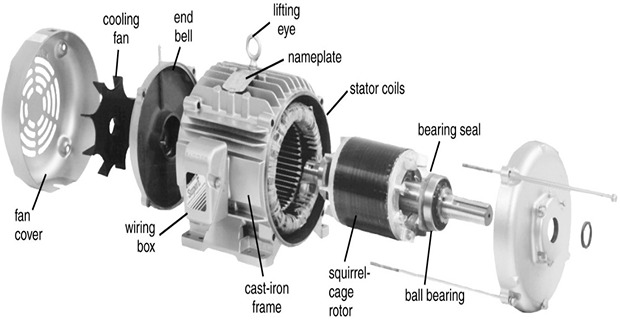
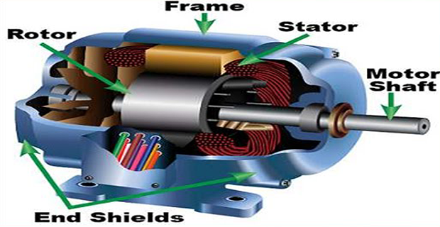
Construction
An induction motor consists essentially of two main parts:
stator and rotor
STATOR:
Made up of a number of stampings, which are slotted to receive the windings
Carries a 3-phase winding and is fed from a 3-phase supply
Wound for a definite number of poles, the exact number of poles being determined by the requirements of speed
Greater the number of poles, lesser the speed and vice versa
Stator winding when supplied with 3-phase currents, produce a magnetic flux, which is of constant magnitude but which revolves at synchronous speed (\(N_s=120f/P\)). This revolving magnetic flux induces an emf in the rotor by mutual induction.
ROTOR:
Squirrel-cage rotor
Phase-wound or wound rotor
Squirrel-cage rotor
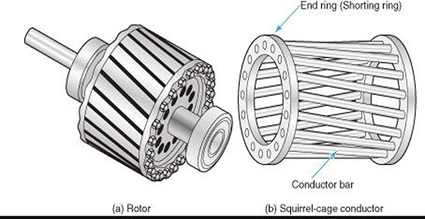
Almost 90% of IMs are squirrel-cage type, because it is simple, rugged, and almost indestructible
Rotor consists of a cylindrical laminated core with parallel slots for carrying the rotor conductors (heavy bars of copper, aluminum or alloys)
One bar is placed in each slot
The rotor bars are electrically welded to two heavy and stout short-circuiting end-rings
Since, rotor bars are permanently short-circuited on themselves, hence it is not possible to add any external resistance in series with rotor circuit for starting purposes
The rotor slots are usually not quite parallel to the shaft but are purposely given a slight skew due to
it helps to make the motor run quietly by reducing the magnetic hum
it helps in reducing the locking tendency of the rotor i.e. the tendency of the rotor teeth to remain under the stator teeth due to direct magnetic attraction between the two.
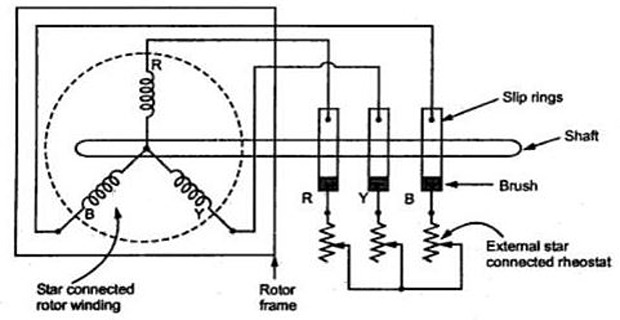
Wound rotor or Slip-ring Induction Motor
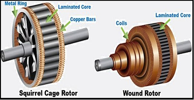
Rotor coils are 3-phase, double layer, distributed winding
Rotor has as many poles as the number of stator poles ans is always wound 3-phase even when the stator is wound two phase
The three phases are starred internally and other three terminals are brought out and connected to three insulated slip-rings mounted on the shaft with brushes resting on them
These three brushes are further externally connected to a 3-phase star-connected rheostat
This makes possible the introduction of additional resistance in the rotor circuit during the starting period for increasing the starting torque of the motor and changing the speed-torque/current characteristics
Under normal running conditions, the slip rings are automatically short-circuited by means of a metal collar, which is pushed along the shaft and connect all the rings together
The brushes are automatically lifted from the slip-rings to reduce the frictional losses and the wear and tear
Thus in normal running conditions, the wound rotor is short-circuited on itself just like the squirrel-cage rotor