Demonstrative Video
Single-Phase Transformer Anatomy: Core & Winding Construction
A look back in the History 
Who invented the transformer?
Otto Blathy, Miksa Deri, Karoly Zipernowsky first designed Later on Lucien Gaulard, Sebstian Ferranti, and William Stanley perfected the design
When was the transformer invented? In 1886, William Stanley, built the first reliable commercial transformer
Where were the first transformers used? Great Barrington, Massachusetts in 1886 In 1891, Mikhail Dobrovsky designed and demonstrated his 3 phase transformers at Frankfurt, Germany


Michael Faraday: principle of electro-magnetic induction in 1831.
The finding forms the basis for many magneto-electric machines.
The earliest use of this phenomenon was in the development of induction coils.
These coils were used to generate high voltage pulses to ignite the explosive charges in the mines.
d.c. power system was in use at that time
Limitation of d.c. system:
for economic transmission of power the generating station and the load center have to be necessarily close to each other
the d.c. generators cannot be scaled up due to the limitations of the commutator
world look for other efficient methods for bulk power generation and transmission.
During the second half of the 19th century the alternators, transformers and induction motors were invented.
These machines work on alternating power supply
With the invention of transformers, it was possible to choose a moderate voltage for generation of a.c power, a high voltage for transmission of this power over long distance, and finally use a small and safe operating voltage at the user end
Transformer: The heart of the AC system

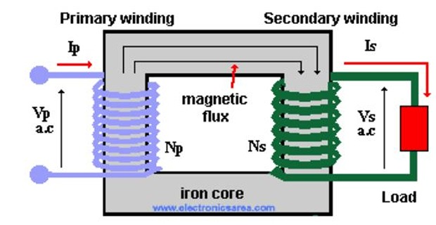

Transformer is a static device
Change the voltage and current levels keeping the power invariant
Consists of two electrical circuit linked by a common magnetic circuit
One of the electrical coils is used for generation of time varying magnetic field
Second coil links to the magnetic field and has induced voltage in it
Magnitude of the induced emf is decided by the number of turns in each coil
Voltage level can be changed by changing the number of turns
Excitation winding is called primary winding and output winding is called secondary
No conductive connection between two electrical circuits and thus provides electrical isolation
Frequency on the two sides will be the same
Efficiency of the conversion is extremely high
No change in the nature of power so ’Transformer’ and not ’Converter’
Transformers are not limited to power systems
frequency operating from few Hz to several MHz
power rating from few milliwatts to several hundred of Megawatts
Electric power generation demand doubles every decade in a developing country
For every MVA of generation, the installed capacity of transformers grows by about 7 MVA
Construction
The construction of the transformer differs based on their end use
Apart from use in power systems, special transformers are used in application like, electronic supplies, rectification, furnaces, traction, etc.
Principle of operation remains the same
Focus on power transformer
Constructional aspects will be discussed under three categories:
Core construction
Winding arrangements
Cooling aspects
Core Construction
Material used for core should be highly permeable (\(\mu_r > 1000\))
High permeability will give low reluctance for the path of the flux
Flux line will confine to the iron core
Silicon steel in the form of thin laminations is used
Over the years, for better magnetic properties, Hot rolled non-oriented to Hot rolled grain oriented steel is used
Later better lamination in Cold Rolled Grain Oriented Steel (CRGOS) became available
The thickness of the laminations progressively got reduced from over 0.5 mm to the present 0.25 mm per lamination
Laminations are coated with a thin layer of insulating varnish, oxide or phosphate
Magnetic material is required to have
high permeability \(\mu\)
high saturation flux density
small area under the B-H loop-to permit high flux density of operation with low magnetizing current and low hysteresis loss
The resistivity of the iron sheet itself is required to be high to reduce the eddy current losses
The eddy current itself is highly reduced by making the laminations very thin
If the lamination is made too thin then the production cost of steel laminations increases
For very small transformers (few VA to few KVA) hot rolled silicon steel laminations in the form of \(E \& I, C \& I\) or \(O\) are used and core cross-section should be square or rectangle

Laminations Silicon content in steel is 3.5%. Above this steel becomes very brittle and also very hard to cut
Saturation flux density of the present steel laminations is about 2%