By the end of this chapter you should be able to:
Define electromagnetic induction and list the ways in which the flux linking a circuit can be changed.
State Faraday's first law and distinguish induced EMF from induced current.
State and apply Faraday's second law, \(e = -N\,\mathrm{d}\Phi/\mathrm{d}t\), and explain the role of the minus sign.
Define flux linkage \(\lambda = N\Phi\) and use it to write the law in its most compact form.
Show from the integral form that the charge transferred depends only on the total flux change, not on how quickly it occurs.
Compute the EMF of a rotating coil and show that it reproduces the EMF equation of Chapter 8.
Compute motional EMF from \(e = Blv\sin\theta\).
Identify where Faraday's law operates in a transformer, a generator and a motor.
Introduction
Part 1 has so far been about magnetic circuits: how flux is established, what governs it, what it costs in heat, and how a magnet can supply it without a coil. All of that is preparation. The pay-off begins here.
In 1831 Michael Faraday established that a changing magnetic flux produces a voltage in any circuit it links. That single discovery converted magnetism from a curiosity into the foundation of electrical engineering, because it works in both directions: move a conductor through a field and you get electricity; supply electricity to a conductor in a field and you get motion. The generator, the motor and the transformer are three consequences of one law.
Chapter 8 has already used a special case of it — the EMF equation \(E = 4.44 f N \Phi_m\) was obtained by differentiating a sinusoidal flux. This chapter states the general law from which that result follows, and Section 10-7 closes the loop by deriving the same 4.44 from a rotating coil instead.
Electromagnetic Induction
The phenomenon by which an EMF is induced in a circuit — and hence current flows when the circuit is closed — when the magnetic flux linking with it changes is called electromagnetic induction.
Three words in that definition carry the whole content, and each is worth isolating:
Changes. A steady flux, however large, induces nothing. A coil sitting in the field of the strongest magnet ever built produces no EMF at all provided nothing moves and nothing varies.
Linking. What matters is the flux that passes through the circuit, not the flux that merely exists nearby. Flux that misses the loop contributes nothing.
Hence current. The EMF appears whether or not the circuit is closed. Current flows only if it is — a distinction Section 10-3 makes explicit.
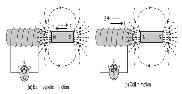
The flux linking a circuit can be varied in several distinct ways, and every machine in this book uses one of them:
By moving a magnet towards or away from the coil.
By moving the coil into or out of the magnetic field.
By changing the area of a coil placed in the magnetic field.
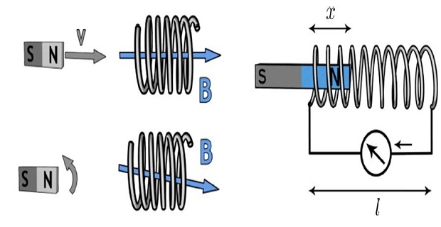
By rotating the coil relative to the magnet.
To these four mechanical methods, two electrical ones must be added, and they are the basis of the transformer:
By changing the current in a neighbouring coil — mutual induction (Chapter 14).
By changing the current in the coil itself — self-induction (Chapter 13).
Faraday's First Law
Faraday's law of electromagnetic induction explains the working principle of most electrical motors, generators, transformers and inductors. It states the relationship between an electric circuit and a magnetic field.
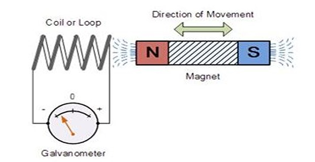
Any change in the magnetic field of a coil of wire will cause an EMF to be induced in the coil.
This EMF is called the induced EMF, and if the conductor circuit is closed, current will also circulate through the circuit — this current is called the induced current.
The first law is qualitative: it says that an EMF appears, and it identifies what causes it. It says nothing about how large the EMF is. That is the business of the second law.
Faraday's Second Law
The second law supplies the quantity. It is the equation on which the rest of this book rests.
where \(N\) is the number of turns and \(\mathrm{d}\Phi/\mathrm{d}t\) is the rate at which the flux linking them changes, in webers per second. The EMF is in volts.
Three features of this equation deserve comment.
The EMF depends on how fast the flux changes, not on how much flux there is. A large steady flux gives nothing; a small flux changing quickly gives a great deal. This is why machines must rotate and why transformers need AC.
Each turn links the same flux, and their EMFs add in series. Winding 1000 turns instead of one multiplies the EMF a thousandfold with no change to the magnetic circuit — the cheapest amplification in engineering.
It states that the induced EMF acts to oppose the change producing it. Chapter 11 develops this and the associated hand rules. Where only magnitude is wanted, the sign is often dropped.
Flux linkage. Because \(N\) and \(\Phi\) always appear together, they are given a combined name. The flux linkage is
and Faraday's second law takes its most compact form:
For a change occurring uniformly over a finite interval, the derivative becomes a simple ratio:
Problem. A coil of 250 turns links a magnetic flux which falls uniformly from 8 mWb to 2 mWb in 0.05 s. Find the induced EMF. If the coil has a resistance of 15 \(\Omega\) and is short-circuited, find the induced current and the total charge that flows.
Induced EMF.
Induced current.
Charge transferred.
Check by flux linkage. The change in flux linkage is
Comment. The second route did not use the time at all. That is not a coincidence, and Section 10-5 explains why.
The Integral Form
Faraday's law can be integrated over an interval, and doing so produces a result that is both useful and slightly surprising.
The current in a circuit of total resistance \(R\) is \(i = |e|/R\), so the charge that flows between times \(t_1\) and \(t_2\) is
Time has cancelled. Move the magnet quickly and you get a large EMF for a short interval; move it slowly and you get a small EMF for a long one. The charge transferred is identical either way. Nature keeps the books in flux linkage, not in volts.
This is the operating principle of the ballistic galvanometer and the fluxmeter. An instrument whose deflection responds to total charge rather than to peak current will read the flux change directly, without any need to control how fast the operator moves the search coil — a considerable practical convenience, and the standard way of measuring flux density before electronic instruments existed.
Problem. A search coil of 60 turns and area 15 cm² is placed with its plane perpendicular to a uniform field of 0.8 T, and is connected to a ballistic galvanometer. The total circuit resistance is 250 \(\Omega\). The coil is suddenly withdrawn from the field. Find the charge that flows. Then compare the EMF and current if the withdrawal takes 0.10 s and if it takes 0.01 s.
Flux linkage change. The flux falls from \(BA\) to zero:
Charge.
| Withdrawal time | EMF | Current | Charge |
|---|---|---|---|
| 0.10 s | 0.72 V | 2.88 mA | 288 μC |
| 0.01 s | 7.20 V | 28.8 mA | 288 μC |
Comment. Ten times the EMF and ten times the current, for one-tenth of the time — and exactly the same charge. This is why a fluxmeter is calibrated in webers rather than in volts, and why measuring flux with a search coil requires no skill at all in how fast you pull it out.
Factors Affecting the EMF
Faraday's law contains only two quantities, but each can be expanded depending on how the flux is being changed.
The conductor is stationary; the flux varies with time. Then
is used directly. This is the transformer case, and Chapter 12 subdivides it into self and mutually induced EMF.
The flux is steady; the conductor moves. For a conductor of active length \(l\) moving with velocity \(v\) at an angle \(\theta\) to the field,
This is the generator case, and it was introduced in Chapter 1.
\(e = Blv\) is not a separate law — it follows from Faraday's law applied to a loop of changing area. If a rod of length \(l\) slides along rails at velocity \(v\), the enclosed area grows at \(\mathrm{d}A/\mathrm{d}t = lv\), so
| Factor | Effect | How it is exploited |
|---|---|---|
| Number of turns \(N\) | Directly proportional | Multi-turn windings everywhere |
| Rate of flux change | Directly proportional | Higher speed or frequency |
| Flux density \(B\) | Directly proportional | Work the iron near saturation |
| Active length \(l\) | Directly proportional | Longer machine stack |
| Velocity \(v\) | Directly proportional | Larger diameter or higher speed |
| Angle \(\theta\) | As \(\sin\theta\) | Maximum when motion is perpendicular to \(B\) |
| Coil area \(A\) | Directly proportional | Larger rotor |
Problem. (a) A conductor 0.5 m long moves at 8 m/s perpendicular to a field of 1.2 T. Find the EMF. Repeat for motion at 30° to the field. (b) An aircraft with a wingspan of 60 m flies at 900 km/h in a region where the vertical component of the Earth's field is 40 \(\mu\)T. Find the EMF between the wingtips.
(a) Conductor. Perpendicular motion, \(\theta = 90^{\circ}\):
At 30°:
(b) Aircraft. Converting the speed,
Comment. The aircraft result is real and measurable, and it is the basis of one method of airspeed sensing. It also illustrates that Faraday's law does not care whether a circuit exists: the EMF appears between the wingtips whether or not anything connects them. Only if a closed path is available does current flow — and for an aircraft in flight, none is, which is why the effect is harmless.
The Rotating Coil
The most important single application of Faraday's law is a coil rotating in a uniform field — the elementary alternator. Working it through recovers the EMF equation of Chapter 8 from an entirely different starting point.
Let a coil of \(N\) turns and area \(A\) rotate at angular velocity \(\omega\) in a uniform field \(B\). When the coil's plane has turned through an angle \(\omega t\) from the position in which it links maximum flux, the linked flux is
Applying Faraday's second law:
The same 4.44 as Chapter 8 — obtained there from a sinusoidally varying flux in a stationary coil, and here from a steady flux and a rotating coil. Two entirely different physical arrangements, one equation, because both are instances of the same law.
Problem. A rectangular coil of 120 turns measuring 200 mm × 150 mm rotates at 1500 rev/min about an axis perpendicular to a uniform field of 0.45 T. Find the frequency, the maximum flux linked, the peak EMF and the RMS EMF. Verify the result against the EMF equation of Chapter 8.
Area and maximum flux.
Frequency and angular velocity. For a two-pole arrangement one revolution gives one cycle:
Peak and RMS EMF.
Verification. Using the EMF equation directly,
(The small discrepancy is only the rounding of \(2\pi/\sqrt{2} = 4.443\) to 4.44.)
Comment. This is a real machine in miniature. Everything Chapters 71 to 77 do to alternators is an elaboration of this calculation: distributing the winding in slots introduces a winding factor, using more poles changes the relation between speed and frequency to \(f = PN/120\), and shaping the pole faces makes the waveform closer to a true sinusoid. The core result — \(E = 4.44 f N \Phi_m\) — survives all of it.
Faraday's Law in Machines
Every device in this book is an application of Faraday's law, differing only in how the flux linkage is made to change.
| Device | What moves | What varies | Type of EMF |
|---|---|---|---|
| Transformer | Nothing | Flux, in time | Statically induced |
| Alternator | Rotor and its field | Flux linking each stator coil | Dynamically induced |
| DC generator | Armature conductors | Flux linking each coil | Dynamically induced |
| DC motor | Armature conductors | Flux linking each coil | Dynamic — the back EMF |
| Induction motor, stator | Nothing | Flux, in time | Statically induced |
| Induction motor, rotor | Rotor, slipping | Flux at slip frequency | Both mechanisms present |
| Inductor | Nothing | Its own current | Self-induced |
In a generator, motion produces an EMF, and Faraday's law is the source of the output. In a motor, the same motion produces a back EMF that opposes the supply — and as Chapter 1 showed, the product of back EMF and armature current is the mechanical power developed.
Faraday's law is therefore not merely the generator's operating principle. It is the mechanism by which energy crosses the air gap in either direction, and the reason a machine cannot convert energy without it.
Problem. A coil of 400 turns links a flux which rises linearly from zero to 5 mWb in 0.02 s, remains constant for the next 0.03 s, and then falls linearly to zero in a further 0.01 s. Sketch the EMF and find its value in each interval.
Interval 1 — rising flux (0 to 0.02 s).
Interval 2 — constant flux (0.02 to 0.05 s).
Interval 3 — falling flux (0.05 to 0.06 s).
and of opposite polarity to \(e_1\), since the flux is now decreasing.
Comment. Notice that intervals 1 and 3 involve the same 5 mWb of flux change but produce different EMFs, because the times differ. The charge transferred, however, would be equal and opposite in the two intervals — so over the whole 0.06 s the net charge is zero, exactly as Section 10-5 predicted.
Applications
The rotating-coil calculation of Section 10-7 in industrial form. Essentially all electrical energy in the world is produced by conductors moving relative to a magnetic field.
Statically induced EMF with no moving part. Chapter 41 applies exactly the derivation of Section 10-4 to two coils sharing a core.
The rate-independent charge result of Section 10-5 makes flux measurable with a coil, a resistor and a charge-sensitive instrument — still the reference method for calibrating field probes.
A changing flux induces EMFs and hence eddy currents directly in the workpiece, as Chapter 7 described. The heating is Faraday's law plus Ohm's law, with no contact at all.
Measuring a large current without breaking the circuit. A Rogowski coil's output is proportional to \(\mathrm{d}i/\mathrm{d}t\) and must be integrated — a direct consequence of Faraday's law being a rate law.
A transmitting coil's alternating flux links a receiving coil, inducing an EMF across an air gap. Modern applications of a principle demonstrated in 1831.
Summary and Key Formulas
Electromagnetic induction is the phenomenon by which an EMF is induced in a circuit when the magnetic flux linking it changes. A steady flux induces nothing.
The flux can be changed by moving the magnet, moving the coil, changing the coil's area, or rotating the coil — and electrically by varying the current in the same or a neighbouring coil.
Faraday's first law: any change in the magnetic field of a coil induces an EMF; if the circuit is closed, an induced current also flows.
Faraday's second law: the magnitude of the induced EMF equals the rate of change of flux linkages, \(e = -N\,\mathrm{d}\Phi/\mathrm{d}t = -\mathrm{d}\lambda/\mathrm{d}t\).
Flux linkage \(\lambda = N\Phi\) in weber-turns is the natural variable, and remains well defined even when different turns link different flux.
The minus sign is Lenz's law — the EMF opposes the change producing it (Chapter 11).
Integrating gives \(q = \Delta\lambda/R\): the charge transferred depends only on the total flux change, not on how fast it happens. Net charge over a complete cycle is zero.
Motional EMF \(e = Blv\sin\theta\) is not a separate law but Faraday's law applied to a loop of changing area.
A rotating coil gives \(E_m = N\Phi_m\omega\) and hence \(E = 4.44 f N\Phi_m\) — the same equation as Chapter 8, from different physics.
| Quantity | Formula | Notes |
|---|---|---|
| Faraday's second law | \(e = -N\dfrac{\mathrm{d}\Phi}{\mathrm{d}t}\) | volts |
| Flux linkage | \(\lambda = N\Phi\) | weber-turns |
| Compact form | \(e = -\dfrac{\mathrm{d}\lambda}{\mathrm{d}t}\) | general; survives leakage |
| Uniform change | \(|e| = N\dfrac{\Delta\Phi}{\Delta t}\) | linear ramp |
| Induced current | \(i = \dfrac{|e|}{R}\) | closed circuit only |
| Charge transferred | \(q = \dfrac{\Delta\lambda}{R} = \dfrac{N\Delta\Phi}{R}\) | independent of rate |
| Motional EMF | \(e = Blv\sin\theta\) | maximum at \(\theta = 90^{\circ}\) |
| From changing area | \(|e| = B\dfrac{\mathrm{d}A}{\mathrm{d}t}\) | gives \(Blv\) for a sliding rod |
| Rotating coil, flux | \(\Phi = \Phi_m\cos\omega t\) | \(\Phi_m = BA\) |
| Rotating coil, EMF | \(e = N\Phi_m\omega\sin\omega t\) | sinusoidal output |
| Peak EMF | \(E_m = N\Phi_m\omega = 2\pi f N\Phi_m\) | volts |
| RMS EMF | \(E = 4.44 f N \Phi_m\) | matches Chapter 8 |
| Frequency from speed | \(f = \dfrac{PN_{\text{rpm}}}{120}\) | \(P\) = poles; 2-pole gives \(f = N/60\) |
Common Mistakes
Thinking a large flux induces a large EMF. Only a changing flux induces anything. The EMF follows the slope of the flux curve, not its height.
Forgetting the number of turns. \(e = N\,\mathrm{d}\Phi/\mathrm{d}t\), not \(\mathrm{d}\Phi/\mathrm{d}t\). With 500 turns the difference is a factor of 500.
Confusing flux with flux linkage. \(\Phi\) is in webers, \(\lambda = N\Phi\) in weber-turns. They differ by \(N\) and the units are not interchangeable.
Believing the EMF requires a closed circuit. The EMF appears regardless; only the current needs a closed path.
Thinking the transferred charge depends on how fast the flux changes. It does not — \(q = \Delta\lambda/R\) contains no time. This is what makes fluxmeters possible.
Dropping the \(\sin\theta\) in motional EMF. A conductor moving along the field lines cuts none of them and generates nothing.
Using \(\Phi_m\) where an RMS quantity is wanted, or vice versa. The EMF equation pairs a peak flux with an RMS voltage — an asymmetry that is easy to overlook.
Assuming one revolution always gives one cycle. True only for a two-pole machine. In general \(f = PN/120\).
Treating \(e = Blv\) as a separate law. It is Faraday's law applied to a loop whose area is changing, and it must give consistent answers with the flux formulation.
Ignoring the minus sign when direction matters. For magnitudes it is harmless; for polarity, phase or stability arguments it is essential. Chapter 11 makes it explicit.
Chapter Review
Work in SI units throughout: flux in webers, area in square metres, time in seconds.
P10.1 A coil of 300 turns links a flux that falls uniformly from 6 mWb to 1 mWb in 0.04 s. Find the induced EMF.
Show answer
\[|e| = N\frac{\Delta\Phi}{\Delta t} = (300)\frac{5\times10^{-3}}{0.04} = (300)(0.125) = 37.5~\mathrm{V}\]P10.2 An EMF of 60 V is induced in a coil when the flux through it changes at 0.15 Wb/s. How many turns has the coil?
Show answer
\[N = \frac{|e|}{\mathrm{d}\Phi/\mathrm{d}t} = \frac{60}{0.15} = 400~\text{turns}\]P10.3 A coil of 500 turns links a flux of 4 mWb. Find the flux linkage. If the flux is reversed in 0.02 s, find the EMF.
Show answer
Reversal means the flux goes from \(+4\) to \(-4\) mWb, a change of 8 mWb:\[\lambda = N\Phi = (500)\left(4\times10^{-3}\right) = 2.0~\mathrm{Wb\text{-}t}\]Reversal doubles the flux change — a very common slip is to use 4 mWb here.\[|e| = (500)\frac{8\times10^{-3}}{0.02} = 200~\mathrm{V}\]P10.4 A flux linkage change of 1.8 Wb-t occurs in a circuit of total resistance 45 \(\Omega\). Find the charge transferred.
Show answer
No time is given, and none is needed.\[q = \frac{\Delta\lambda}{R} = \frac{1.8}{45} = 0.040~\mathrm{C} = 40~\mathrm{mC}\]P10.5 A coil of 80 turns and area 0.025 m² rotates at 3000 rev/min in a uniform field of 0.6 T (two-pole). Find \(f\), \(E_m\) and \(E_{\text{rms}}\).
Show answer
\[f = \frac{3000}{60} = 50~\mathrm{Hz}, \qquad \omega = 314.16~\mathrm{rad/s}, \qquad \Phi_m = (0.6)(0.025) = 0.015~\mathrm{Wb}\]\[E_m = N\Phi_m\omega = (80)(0.015)(314.16) = 377.0~\mathrm{V}\]Check: \(4.44(50)(80)(0.015) = 266.4\) V \(\checkmark\)\[E_{\text{rms}} = \frac{377.0}{\sqrt{2}} = 266.6~\mathrm{V}\]P10.6 A conductor 0.8 m long moves at 12 m/s in a field of 0.9 T. Find the EMF when the motion is (a) perpendicular to the field and (b) at 45° to it.
Show answer
\[e_{90} = Blv = (0.9)(0.8)(12) = 8.64~\mathrm{V}\]\[e_{45} = (8.64)\sin 45^{\circ} = (8.64)(0.7071) = 6.11~\mathrm{V}\]P10.7 A search coil of 50 turns and area 8 cm² lies perpendicular to a field of 0.5 T, in a circuit of resistance 100 \(\Omega\). The coil is suddenly reversed. Find the charge that flows.
Show answer
Reversal changes the linked flux from \(+BA\) to \(-BA\), so \(\Delta\Phi = 2BA\):\[\Delta\Phi = 2(0.5)\left(8\times10^{-4}\right) = 8.0\times10^{-4}~\mathrm{Wb}\]Reversing gives twice the charge that withdrawing would.\[\Delta\lambda = (50)\left(8.0\times10^{-4}\right) = 0.040~\mathrm{Wb\text{-}t}, \qquad q = \frac{0.040}{100} = 4.0\times10^{-4}~\mathrm{C} = 400~\mu\mathrm{C}\]P10.8 A 200-turn coil links a flux that rises linearly from 0 to 4 mWb in 0.01 s, then falls linearly back to zero in 0.04 s. Find the EMF in each interval and the net charge over the whole 0.05 s.
Show answer
The second EMF has the opposite polarity. The flux returns to its starting value, so \(\Delta\lambda = 0\) over the whole interval and the net charge is zero — whatever the resistance.\[|e_1| = (200)\frac{4\times10^{-3}}{0.01} = 80~\mathrm{V}, \qquad |e_2| = (200)\frac{4\times10^{-3}}{0.04} = 20~\mathrm{V}\]P10.9 A four-pole alternator runs at 1500 rev/min. Find the frequency, and the RMS EMF per phase if each phase has 240 turns linking a maximum flux of 25 mWb.
Show answer
\[f = \frac{PN}{120} = \frac{(4)(1500)}{120} = 50~\mathrm{Hz}\]Note the four-pole machine gives 50 Hz at half the speed a two-pole machine would need. A real alternator's EMF is slightly lower because of the winding factor introduced in Chapter 73.\[E = 4.44 f N \Phi_m = (4.44)(50)(240)\left(25\times10^{-3}\right) = 1332~\mathrm{V}\]P10.10 A magnet is withdrawn from a coil in 0.5 s, and then in 0.05 s. Compare the EMF, the peak current and the charge in the two cases.
Show answer
The flux change \(\Delta\lambda\) is the same in both cases.\[e \propto \frac{1}{\Delta t} \quad\Longrightarrow\quad \text{EMF is } 10\times \text{ greater in the second case}\]\[i = \frac{e}{R} \quad\Longrightarrow\quad \text{current is also } 10\times \text{ greater}\]Ten times the current for one-tenth of the time. This is the result that makes the ballistic galvanometer a flux-measuring instrument.\[q = \frac{\Delta\lambda}{R} \quad\Longrightarrow\quad \text{charge is } \textbf{identical}\]
MCQ 1. An EMF is induced in a coil when:
(a) the flux through it is large (b) the flux through it changes (c) the current is large (d) the coil is closedShow answer
(b) the flux through it changes. A steady flux, however large, induces nothing.MCQ 2. Faraday's second law states that the induced EMF equals the:
(a) flux linkage (b) rate of change of flux linkages (c) flux density (d) reluctanceShow answer
(b) the rate of change of flux linkages, \(e = -\mathrm{d}\lambda/\mathrm{d}t\).MCQ 3. The unit of flux linkage is:
(a) weber (b) tesla (c) weber-turn (d) ampere-turnShow answer
(c) weber-turn, equivalently the volt-second.MCQ 4. The minus sign in Faraday's law expresses:
(a) Ohm's law (b) Lenz's law (c) Ampère's law (d) Gauss's lawShow answer
(b) Lenz's law — the induced EMF opposes the change producing it.MCQ 5. The charge transferred when a coil's flux linkage changes by \(\Delta\lambda\) in a circuit of resistance \(R\) is:
(a) \(\Delta\lambda R\) (b) \(\Delta\lambda/R\) (c) \(\Delta\lambda/Rt\) (d) \(\Delta\lambda t/R\)Show answer
(b) \(\Delta\lambda/R\) — with no dependence on time at all.MCQ 6. A conductor moving parallel to the magnetic field lines generates:
(a) maximum EMF (b) half the maximum (c) zero EMF (d) a reversed EMFShow answer
(c) zero EMF. With \(\theta = 0\), \(\sin\theta = 0\) — the conductor cuts no flux lines.MCQ 7. In a coil rotating in a uniform field, the EMF is maximum when the flux linkage is:
(a) maximum (b) zero (c) half its maximum (d) negativeShow answer
(b) zero. The EMF follows the slope of the flux curve, which is steepest as the flux passes through zero.MCQ 8. Doubling the number of turns of a coil, all else unchanged, changes the induced EMF by a factor of:
(a) 1 (b) 2 (c) 4 (d) 1/2Show answer
(b) 2. EMF is directly proportional to \(N\), since each turn contributes in series.MCQ 9. An EMF is induced in an open-circuited coil. The induced current is:
(a) maximum (b) zero (c) equal to \(e/R\) (d) undefinedShow answer
(b) zero. The EMF exists, but current needs a closed path.MCQ 10. A search coil is reversed in a field rather than withdrawn. The charge transferred is:
(a) the same (b) half (c) double (d) zeroShow answer
(c) double, because the flux changes from \(+BA\) to \(-BA\), a change of \(2BA\) rather than \(BA\).
State Faraday's two laws and explain precisely what each adds that the other does not.
Why is flux linkage a more useful variable than flux? Give a situation in which \(N\Phi\) is ambiguous but \(\lambda\) is not.
Explain why the charge transferred is independent of how fast the flux changes, and how this makes a fluxmeter possible.
Show that \(e = Blv\) follows from \(e = -\mathrm{d}\lambda/\mathrm{d}t\) rather than being an independent law.
In a rotating coil the EMF is zero when the flux linkage is greatest. Explain this in terms of the slope of the flux waveform, and relate it to the 90° phase result of Chapter 8.
The same equation \(E = 4.44 f N\Phi_m\) was obtained in Chapter 8 from a stationary coil and here from a rotating one. Explain why two such different arrangements give identical results.
Explain why Faraday's law is described as the mechanism by which energy crosses the air gap in both a generator and a motor.
Faraday's law gives the magnitude of the induced EMF but has been used so far only for magnitudes — the minus sign has been noted and set aside. Chapter 11 takes it up properly. Lenz's law states that the induced effect always opposes the change producing it, and with Fleming's right- and left-hand rules it fixes the direction of every EMF and force in this book.
Chapter 12 then divides induced EMF into its two families — statically and dynamically induced — which are the transformer and the generator in their purest forms. Chapters 13 and 14 introduce self and mutual inductance, showing that \(L = N^{2}/S\) as Chapter 2 hinted. By Chapter 15 the energy methods begin, and from there force and torque follow directly.