By the end of this chapter you should be able to:
Define conductor, turn, coil, coil side, coil group and winding, and relate \(Z\), \(C\) and turns per coil.
Explain why multi-turn coils are used and what limits how many turns they may have.
Distinguish front-end and back-end connectors and explain the inductance effect of the overhang.
Compute pole pitch in slots and in conductors.
Define and relate the back, front, resultant and commutator pitches.
Classify a coil as full-, short- or over-pitched and state the effect on EMF.
Explain single and double re-entrancy.
State why the Gramme-ring winding was abandoned in favour of the drum winding.
What an Armature Winding Is
At the outer periphery of an armature core, slots are cut.
In these slots a number of conductors are placed, connected with each other in a proper arrangement forming series–parallel paths depending upon the requirement.
This arrangement of connections is known as the armature winding.
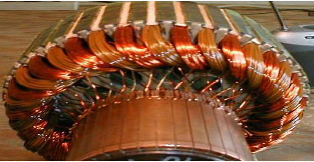

To understand the armature winding schemes it is desirable to have an idea of the terms set out in the sections that follow.
Conductor, Turn and Coil
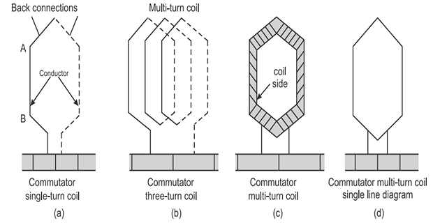
The length of wire embedded in the armature core and lying within the magnetic field is called the conductor.
It may have one or more parallel strands.
The total number of conductors in the armature winding is represented by the symbol \(Z\).
Two conductors lying in a magnetic field, connected in series at the back so that the EMFs induced in them are additive, is known as a turn.
One turn is therefore always two conductors — the single most useful fact for keeping the bookkeeping straight.
A coil may be a single-turn coil having only two conductors, or a multi-turn coil having more than two conductors.
The bunch of conductors may be wrapped in cotton tape before being placed in the armature slot.
A multi-turn coil can be represented by a single-line diagram.
The total number of coils in the armature winding is represented by the symbol \(C\).
where \(T\) is the number of turns per coil. For a double-layer winding there is one coil per slot, so \(C = S\), and the number of commutator segments also equals \(C\).
The case for them: multi-turn coils are used to develop higher voltages. When the armature conductors are many, it is not feasible to use single-turn coils, because that would require a very large number of commutator segments; and if used, it would not give sparkless commutation. Moreover, it would not be economical, owing to the extra copper in the end connections.
The case against too many: Chapter 22 showed that the voltage between adjacent commutator segments is \(EP/C\) for a lap winding, and must stay below about 15 V. Fewer coils means fewer segments, and fewer segments means more volts across each mica gap. Example 24.5 shows how quickly this becomes the binding constraint.
Problem. A 4-pole armature has 24 slots with a double-layer winding of 3-turn coils. Find the number of coils, the total conductors, the conductors per slot, the number of commutator segments, and the pole pitch in both slots and conductors.
Coils. A double-layer winding has two coil sides per slot, and each coil has two sides, so there is one coil per slot:
Total conductors.
Conductors per slot.
which is two coil sides of 3 conductors each — consistent with a double layer.
Commutator segments. One per coil, so \(C = 24\).
Pole pitch.
Comment. The four counts — slots, coils, segments, conductors — are all tied together, and a winding problem is largely a matter of not losing track of which is which. The commonest slip is to confuse turns with conductors, which throws \(Z\) out by a factor of two and every EMF calculation with it.
Coil Sides, Groups and Winding
Each coil, whether single-turn or multi-turn, has two sides called coil sides. Both are embedded in two different slots as per the winding design — nearly a pole pitch apart.
A group of coils may have one or more coils.
When a number of coil groups are arranged on the armature in a particular fashion as per the design, it is called an armature winding.
End Connectors and Inductance
A wire used to connect one coil side to the other coil side at the back of the armature.
A wire used to connect the end of a coil at the front to the commutator segment.
All the coils have some inductance effect, as the current in them is changing.
Due to the inductance effect the flow of current is opposed, causing a reduction in the resultant output voltage.
Overhanging end connections have an adverse effect due to inductance.
This is not a minor detail. The overhang carries current but lies outside the magnetic field, so it generates no EMF at all — it is pure resistance and pure inductance, contributing loss and reactance and nothing else. That inductance is precisely the \(L\) in Chapter 23's reactance voltage \(E_r = L\,\Delta I/T_c\), and shortening the overhang is one of the few ways a designer can reduce it. Section 24-7 shows how short-pitching does exactly that.
Pole Pitch
Pole pitch is defined as the number of armature slots per pole. It may also be defined as the number of armature conductors per pole.
For instance, if there are 36 conductors for 4 poles then the pole pitch will be \(36/4 = 9\) conductors per pole.
The Four Winding Pitches
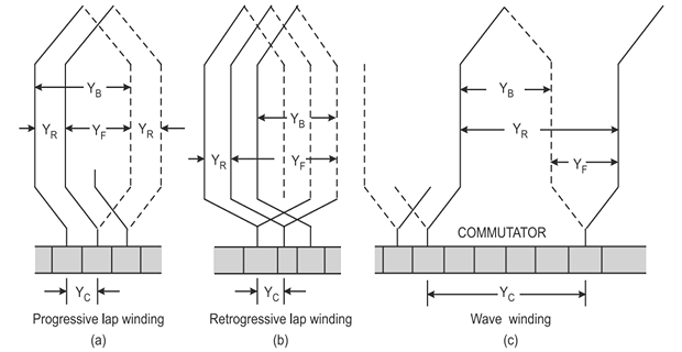
The distance, in terms of the number of armature conductors, between the first and last conductor of the same coil — that is, the distance between the two coil sides of the same coil.
It is also called the coil span or coil spread.
The distance, in terms of the number of armature conductors or slots, between the second conductor of one coil and the first conductor of the next coil, which are connected to the same commutator segment on the front.
The distance, in terms of the number of armature conductors or slots, between the start of one coil and the start of the next coil to which it is connected.
The distance measured in terms of commutator segments between the segments to which the two ends of a coil are connected.
and in every double-layer winding both \(Y_b\) and \(Y_F\) must be odd, so that each coil goes from a top layer to a bottom layer and back.
The back pitch is chosen close to the pole pitch in conductors:
The two families differ in the commutator pitch, and that difference is what makes one lap and the other wave:
| Quantity | Lap winding | Wave winding |
|---|---|---|
| Commutator pitch \(Y_C\) | \(\pm 1\) | \(\dfrac{C \pm 1}{P/2}\) |
| Resultant pitch \(Y_R\) | \(Y_b - Y_F = \pm 2\) | \(Y_b + Y_F = 2Y_{av}\) |
| Average pitch \(Y_{av}\) | — | \(\dfrac{Z \pm 2}{P}\) |
| Sign \(+\) | Progressive | Progressive |
| Sign \(-\) | Retrogressive | Retrogressive |
| Parallel paths \(A\) | \(P\) | 2 |
Problem. A 4-pole lap winding has 48 armature conductors. Find the back, front, resultant and commutator pitches for both progressive and retrogressive connection.
Back pitch. Start from the pole pitch in conductors:
Since \(Y_b\) must be odd, take \(Y_b = 11\) (or 13).
Progressive lap (\(Y_C = +1\), so \(Y_R = +2\)):
Both 11 and 9 are odd \(\checkmark\)
Retrogressive lap (\(Y_C = -1\), so \(Y_R = -2\)):
Both 11 and 13 are odd \(\checkmark\)
Comment. In a progressive winding the front pitch is less than the back pitch, so the winding advances round the armature; in a retrogressive one it is greater and the winding works backwards. Electrically the two are equivalent — same EMF, same paths — and the choice is made on the convenience of the end connections. Retrogressive windings use slightly more copper, so progressive is the usual choice.
Problem. A 4-pole wave winding has 30 armature conductors. Find the average pitch and a workable set of back and front pitches for both connections.
Average pitch.
Retrogressive (\(Y_{av} = 7\)):
Progressive (\(Y_{av} = 8\)):
In both cases \(Y_b\) and \(Y_F\) are odd, as required, and \(Y_b\) is close to the pole pitch \(Z/P = 7.5\) conductors.
Comment. Note that a wave winding adds its pitches where a lap winding subtracts them. That is the whole geometric difference: a lap coil comes back almost to where it started, while a wave coil marches on around the armature and does not close until it has passed every pole pair. It is why one gives \(P\) paths and the other only two.
The \(\pm 2\) in the average pitch exists because a winding that closed on itself exactly — \(Y_{av} = Z/P\) — would return to its starting conductor after one trip round and leave the rest unconnected. The offset of one conductor per trip is what makes the winding progress.
Coil Span and Pitching
The coil span or coil pitch is the distance, in terms of the number of armature conductors or slots, between two sides of the same coil. It may be equal to, less than, or more than the pole pitch — and accordingly the coils are known as full-pitched, short-pitched or over-pitched.
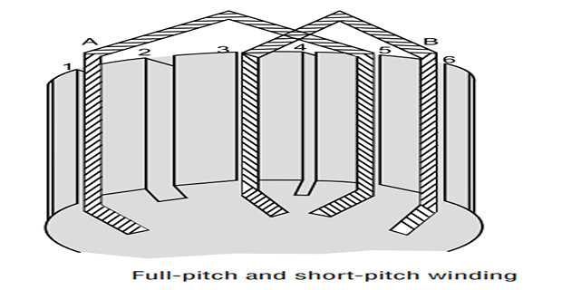
Take a pole pitch of 4 slots.
Coil A: one side in slot 1, the other in slot 5. The coil span is \(5 - 1 = 4\), equal to the pole pitch, so coil A is full-pitched.
Coil B: the coil span is \(6 - 3 = 3\), less than the pole pitch, so coil B is short-pitched.
The induced EMF in a coil is the arithmetic sum of the EMFs induced in the two sides of the same coil, since the coil sides are displaced by 180° electrical.
The two sides lie at similar positions under two adjacent poles — one north, one south — so their EMFs reinforce exactly.
The resultant induced EMF is reduced, because the two sides fall under the influence of the same pole at some instant.
At that instant the EMFs in the two sides oppose each other, so the resultant is a phasor rather than arithmetic sum.
The copper used for end connections is reduced substantially, which reduces the cost of the machine.
It improves commutation — reducing sparking at the brushes — because the inductance of the overhang connections is reduced.
It reduces the copper losses and improves the efficiency to some extent.
Hence short-pitched windings are frequently used.
The size of the EMF loss is the pitch factor of Chapter 19, \(k_c = \cos(\alpha/2)\), where \(\alpha\) is the chording angle. Example 24.4 shows how small it is in practice.
Problem. A 4-pole armature has 36 slots. A coil is short-pitched by one slot. Find the coil span, the chording angle, the pitch factor and the percentage EMF lost.
Pole pitch.
A full-pitch coil therefore lies in slots 1 and 10.
Coil span. Short-pitched by one slot, so slots 1 and 9, giving a span of 8 slots.
Chording angle. One pole pitch is 180° electrical spread over 9 slots:
Pitch factor.
EMF lost.
Comment. Under two percent of the EMF, in exchange for shorter end connections, lower overhang inductance and better commutation. Given that Chapter 23 showed the reactance voltage is the binding constraint on a DC machine, buying a reduction in \(L\) for 1.5 % of the voltage is an excellent trade — and the lost voltage can be recovered simply by adding a turn or two per coil.
Degree of Re-entrancy
An armature winding may be single re-entrant or multiple re-entrant.
While tracing through a winding once, if all armature conductors are included on returning to the starting point, the winding is called a single re-entrant winding.
It will be double re-entrant if only half of the conductors are included in tracing through the winding once.
Gramme-Ring Winding
The continuous or closed armature windings are of two types: the Gramme-ring winding and the drum winding.
The Gramme-ring type is an early form of armature winding, in which the conductors are wound right through the centre of a ring-shaped core. It has been replaced by the more efficient drum-type winding for the reasons below.
Only half the coil was available to link with the pole flux. The other half of the winding lay inside the core and was used only as connectors — so there was a wastage of copper.
As each turn had to pass through the centre of the core, it was difficult to wind and required more labour, hence was costlier.
The maintenance and repairs were more costly.
Insulation of the winding was also difficult.
For the same pole flux and armature velocity, the EMF induced in a ring winding was half that induced in a drum winding having the same number of coils.
The construction had a large air gap, so stronger field excitation was required to produce the required flux.
The first and fifth points are the same point counted twice, and together they are decisive. Half the copper generated nothing, so for the same conductor count the machine gave half the voltage — and paid for the idle half in resistance, weight and cost. No refinement could rescue an arrangement that wasteful.
Drum Winding
Conductors are housed in slots cut over the armature surface and connected to one another at the front and back through connectors.
The whole of the copper used is active except the end connectors — that is, it cuts flux and is therefore active in generating EMF.
The coils can be pre-formed and insulated before being placed on the armature, which reduces the construction cost.
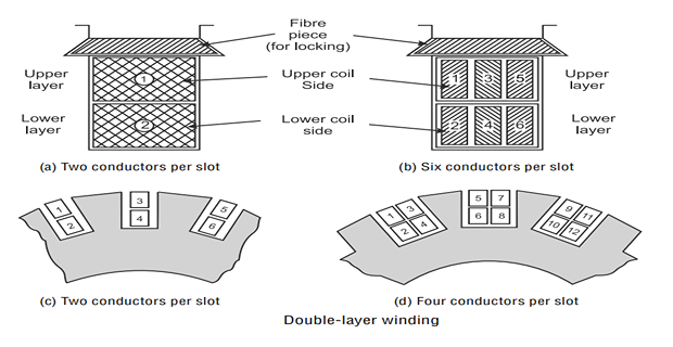
Only one conductor or one coil side is placed in each armature slot.
Rarely used, because of its greater cost.
There are two conductors or coil sides per slot, arranged in two layers.
Mostly employed, for reasons of economy.
The advantage of the double layer is the same one Chapter 19 gave for AC machines: every coil is identical and can be machine-formed, and because each slot holds sides belonging to two different coils, the designer is free to choose any coil span — including a short one. Short-pitching is only possible at all in a double-layer winding.
Problem. A 4-pole lap-wound machine needs 480 armature conductors and generates 400 V. Compare 1-, 2- and 4-turn coils by the number of commutator segments required and the resulting volts per segment. Which are acceptable?
Coils and segments. From \(Z = 2CT\):
Volts per segment. From Chapter 22, for a lap winding \(V_{\text{seg}} = EP/C\):
| Turns \(T\) | Coils \(C\) = segments | \(V_{\text{seg}} = EP/C\) | Verdict |
|---|---|---|---|
| 1 | 240 | 6.67 V | Safe, but a large and costly commutator |
| 2 | 120 | 13.33 V | Acceptable — inside the 15 V guideline |
| 4 | 60 | 26.67 V | Rejected — flashover risk |
Comment. The source's two statements — that multi-turn coils develop higher voltages, and that too many single-turn coils make an impractical commutator — are both true and pull in opposite directions. The volts-per-segment limit decides where the balance lies, and here it permits 2 turns per coil but not 4.
Note that \(Z\) is fixed at 480 in all three cases, so the generated EMF is the same 400 V throughout. What changes is not how much voltage the machine makes but how finely that voltage is divided among the segments — and the mica between two segments must withstand whatever fraction it is given.
Coil Manufacture and Insulation
- The coils are usually wound on machine-driven formers, which give them their proper shape.
- The turns may be bound together with cotton tape.
- The ends are left bare so that they can be soldered to the commutator segments.
- The coils are then dipped into an insulating compound such as asphalt and dried.
- Before the coils are placed in the slots, liners of leatheroid are inserted to provide mechanical protection to the coil insulation against the sharp edges of the slot.
If the machine is to be operated at high temperatures, other materials may be used — such as mica and paper tape, fibreglass tape, and silicone-impregnated insulation.
Summary and Key Formulas
Conductors placed in armature slots and connected to form series–parallel paths constitute the armature winding.
A conductor is one length of wire in the field; a turn is two conductors joined at the back; a coil may be single- or multi-turn. Hence \(Z = 2CT\).
Multi-turn coils develop higher voltages and need fewer segments, but raise the volts per segment — which limits how many turns are practical.
Back-end connectors join coil side to coil side; front-end connectors join coil ends to segments. The overhang generates no EMF but contributes resistance and the inductance responsible for the reactance voltage.
Pole pitch is \(S/P\) slots or \(Z/P\) conductors — always state which.
The four pitches: back \(Y_b\), front \(Y_F\), resultant \(Y_R\) and commutator \(Y_C\). Lap subtracts (\(Y_R = Y_b - Y_F\)); wave adds (\(Y_R = Y_b + Y_F\)). Both \(Y_b\) and \(Y_F\) must be odd.
A coil is full-, short- or over-pitched as its span equals, falls short of, or exceeds the pole pitch. Full-pitch gives the arithmetic sum of the two side EMFs; otherwise the phasor sum, reduced by \(k_c = \cos(\alpha/2)\).
Short-pitching saves end-connection copper, improves commutation by lowering overhang inductance, and reduces copper loss — at a cost of only 1–2 % of EMF.
A winding is single re-entrant if one trace covers all conductors, double re-entrant if only half.
The Gramme-ring winding wasted half its copper inside the core and gave half the EMF of a drum winding. The drum winding, normally double-layer, replaced it.
| Quantity | Formula | Notes |
|---|---|---|
| Total conductors | \(Z = 2CT\) | one turn = two conductors |
| Coils, double layer | \(C = S\) | one coil per slot |
| Commutator segments | \(= C\) | one per coil |
| Conductors per slot | \(Z/S = 2T\) | double layer |
| Pole pitch | \(S/P\) slots, \(Z/P\) conductors | state the unit |
| Back pitch | \(Y_b \approx Z/P\), odd | the coil span |
| Resultant pitch, lap | \(Y_R = Y_b - Y_F = \pm 2\) | \(Y_C = \pm 1\) |
| Resultant pitch, wave | \(Y_R = Y_b + Y_F = 2Y_{av}\) | — |
| Average pitch, wave | \(Y_{av} = \dfrac{Z \pm 2}{P}\) | must be an integer |
| Chording angle | \(\alpha = \dfrac{180^{\circ}}{S/P} \times \text{slots short}\) | electrical degrees |
| Pitch factor | \(k_c = \cos(\alpha/2)\) | Chapter 19 |
| Volts per segment | \(EP/C\) lap | keep below ~15 V |
Common Mistakes
Confusing turns with conductors. One turn is two conductors, so \(Z = 2CT\) — omitting the 2 halves every EMF.
Taking \(C = Z/2\) for a multi-turn winding. That holds only for single-turn coils.
Mixing pole pitch in slots with pole pitch in conductors. They differ by the conductors per slot.
Choosing an even back pitch. Both \(Y_b\) and \(Y_F\) must be odd in a double-layer winding.
Adding the pitches for a lap winding. Lap subtracts, wave adds.
Forgetting the \(\pm 2\) in the wave average pitch. Without the offset the winding closes on itself prematurely.
Assuming short-pitching is a defect. The EMF loss is 1–2 %; the gains in copper, inductance and commutation outweigh it.
Thinking the overhang generates EMF. It lies outside the field and contributes only loss and inductance.
Believing more turns per coil always gives more voltage. With \(Z\) fixed the EMF is unchanged; only the volts per segment rise.
Assuming a Gramme-ring winding is merely old-fashioned. It gives literally half the EMF of a drum winding with the same copper.
Chapter Review
Write down \(S\), \(P\), \(C\), \(T\) and \(Z\) before anything else, and check \(Z = 2CT\) every time.
P24.1 A 6-pole armature has 36 slots, double-layer, with 4-turn coils. Find \(C\), \(Z\), conductors per slot, segments and pole pitch in slots and conductors.
Show answer
\[C = S = 36~\text{coils}, \qquad Z = 2CT = (2)(36)(4) = 288\]\[\frac{Z}{S} = 8~\text{conductors/slot}, \qquad \text{segments} = 36\]\[\text{pole pitch} = \frac{36}{6} = 6~\text{slots} = \frac{288}{6} = 48~\text{conductors}\]P24.2 A 4-pole lap winding has 40 conductors. Find \(Y_b\), \(Y_F\), \(Y_R\) and \(Y_C\) for a progressive winding.
Show answer
\[\frac{Z}{P} = \frac{40}{4} = 10 \quad\text{(even)} \quad\Longrightarrow\quad Y_b = 9 \ \text{or}\ 11; \ \text{take } Y_b = 9\]Both 9 and 7 are odd \(\checkmark\)\[Y_C = +1, \quad Y_R = +2, \quad Y_F = Y_b - Y_R = 9 - 2 = 7\]P24.3 A 6-pole wave winding has 42 conductors. Find the possible average pitches and a workable \(Y_b\), \(Y_F\) pair.
Show answer
Neither is an integer, so no wave winding is possible with 42 conductors and 6 poles. The conductor count must be changed — for example \(Z = 40\) gives \(Y_{av} = (40+2)/6 = 7\), and then \(Y_b + Y_F = 14\) with \(Y_b = Y_F = 7\).\[Y_{av} = \frac{42 \pm 2}{6} = \frac{44}{6} \ \text{or} \ \frac{40}{6}\]This is a real design constraint: wave windings only exist for conductor counts satisfying the integer condition, which is why \(Z\) is often chosen last.
P24.4 A 6-pole armature has 54 slots. A coil is short-pitched by 2 slots. Find the chording angle and pitch factor.
Show answer
\[\text{pole pitch} = \frac{54}{6} = 9~\text{slots}, \qquad \text{slot angle} = \frac{180^{\circ}}{9} = 20^{\circ}\]An EMF loss of 6.03 %.\[\alpha = (2)(20^{\circ}) = 40^{\circ}, \qquad k_c = \cos 20^{\circ} = 0.9397\]P24.5 A 4-pole lap machine generates 500 V with 600 conductors. Find the maximum turns per coil for which the volts per segment stays below 15 V.
Show answer
\[V_{\text{seg}} = \frac{EP}{C} \lt 15 \quad\Longrightarrow\quad C \gt \frac{(500)(4)}{15} = 133.3\]So 2 turns per coil, giving \(C = 150\) and \(V_{\text{seg}} = 2000/150 = 13.33\) V.\[C = \frac{Z}{2T} = \frac{600}{2T} \gt 133.3 \quad\Longrightarrow\quad T \lt 2.25\]P24.6 Explain why the back and front pitches must both be odd in a double-layer winding.
Show answer
Number the conductors so that odd numbers are in the top layer and even numbers in the bottom. A coil must run from a top conductor in one slot to a bottom conductor in another, so it must go from an odd number to an even one — a difference that is necessarily odd.The same applies to the front connection back to the next coil's top conductor. An even pitch would connect top to top or bottom to bottom, which the geometry of a two-layer slot does not permit.
P24.7 Why does a Gramme-ring winding give half the EMF of a drum winding with the same number of coils?
Show answer
In a ring winding each turn passes through the centre of the core. Only the portion on the outer surface lies in the air-gap field and cuts flux; the inner portion is shielded by the iron and cuts nothing.So only one side of each turn generates, whereas in a drum winding both sides lie under poles of opposite polarity and their EMFs add. Same copper, half the output — and the idle half still contributes resistance and weight.
P24.8 Explain how short-pitching improves commutation.
Show answer
A short-pitched coil has shorter overhang end connections, and the overhang is a significant part of the coil's self-inductance \(L\).From Chapter 23, the reactance voltage is \(E_r = L\,\Delta I/T_c\). Reducing \(L\) reduces \(E_r\) in direct proportion, so the coil current reverses more nearly linearly within the commutation period and less current remains to be interrupted at the trailing brush edge. Less sparking, and a longer commutator life.
P24.9 A machine has 200 single-turn coils. It is rewound with 100 two-turn coils, keeping \(Z\) unchanged. What changes and what does not?
Show answer
Unchanged: \(Z\), and therefore the generated EMF, since \(E \propto Z\).Changed: the commutator has 100 segments instead of 200, so the volts per segment doubles. Each coil now has twice the turns and therefore roughly four times the inductance (since \(L \propto N^{2}\)), which raises the reactance voltage substantially.
The machine is cheaper to build and worse to commutate — the trade of Example 24.5, seen from the other direction.
P24.10 Why is a single-layer drum winding rarely used?
Show answer
With only one coil side per slot, a given number of coils needs twice as many slots — a larger, more expensive armature for the same winding. The source states this plainly: it is rarely used because of its greater cost.There is a second reason. In a single-layer winding the coil span is fixed by the slot geometry, so short-pitching is impossible — forfeiting the copper saving and the commutation benefit of Section 24-7.
MCQ 1. One turn consists of:
(a) one conductor (b) two conductors (c) one coil (d) two coilsShow answer
(b) two conductors, connected in series at the back so their EMFs add.MCQ 2. For a winding of \(C\) coils of \(T\) turns each, the conductor count is:
(a) \(CT\) (b) \(2CT\) (c) \(C/T\) (d) \(4CT\)Show answer
(b) \(2CT\).MCQ 3. The number of commutator segments equals the number of:
(a) slots (b) poles (c) coils (d) conductorsShow answer
(c) coils. For a double-layer winding this also equals the number of slots.MCQ 4. The back pitch is also known as the:
(a) commutator pitch (b) coil span (c) pole pitch (d) resultant pitchShow answer
(b) coil span, or coil spread.MCQ 5. In a lap winding the resultant pitch is:
(a) \(Y_b + Y_F\) (b) \(Y_b - Y_F\) (c) \(Y_bY_F\) (d) \(2Y_b\)Show answer
(b) \(Y_b - Y_F\), and it equals \(\pm 2\). A wave winding adds them.MCQ 6. In a double-layer winding the back and front pitches must be:
(a) both even (b) both odd (c) one odd, one even (d) equalShow answer
(b) both odd, so each connection runs from a top-layer conductor to a bottom-layer one.MCQ 7. A coil whose span is less than the pole pitch is called:
(a) full-pitched (b) short-pitched (c) over-pitched (d) re-entrantShow answer
(b) short-pitched, or chorded.MCQ 8. In a full-pitched coil the resultant EMF is the:
(a) phasor sum of the side EMFs (b) arithmetic sum (c) difference (d) zeroShow answer
(b) arithmetic sum, since the sides are 180° electrical apart and their EMFs are exactly in phase as measured round the coil.MCQ 9. A winding in which one trace includes only half the conductors is:
(a) single re-entrant (b) double re-entrant (c) full-pitched (d) simplex lapShow answer
(b) double re-entrant — effectively two independent windings on one armature.MCQ 10. The Gramme-ring winding was abandoned chiefly because:
(a) it sparked badly (b) half the copper generated no EMF (c) it needed a commutator (d) it could not be laminatedShow answer
(b) half the copper generated no EMF, lying inside the core where it cut no flux.
Define conductor, turn, coil and coil side, and derive the relation between \(Z\), \(C\) and turns per coil.
Explain why multi-turn coils are used, and what limits the number of turns.
Distinguish front-end from back-end connectors, and explain the adverse effect of the overhang.
Define the four winding pitches and state the relations between them for lap and wave windings.
Explain why both the back and front pitches must be odd numbers.
Compare full-, short- and over-pitched coils, explaining how the resultant EMF is formed in each case.
Give three advantages of short-pitched windings and quantify the EMF cost.
List the disadvantages of the Gramme-ring winding and explain why the drum winding superseded it.
The vocabulary is now in place. Chapter 25 uses it to construct the two windings themselves — lap and wave — with complete winding tables and developed diagrams for real slot counts, the conditions under which each is possible, and the equaliser rings that lap windings require but wave windings do not.
The reason for equalisers is worth anticipating. A lap winding has \(P\) parallel paths, each lying under a different pair of poles. If those poles are not exactly equal — and no real machine's are — the paths generate slightly different EMFs and a circulating current flows between them, through the brushes. Equaliser rings give that current a low-resistance path of its own, keeping it out of the brushes. A wave winding needs none, because each of its two paths passes under every pole in turn and so automatically averages any inequality.
Chapter 26 then returns to the machine types classified in Chapter 20 and develops the applications of each, before Chapter 27 puts the EMF equation to work on design problems.