By the end of this chapter you should be able to:
Classify DC generators by their method of field excitation.
State the merits and the one serious defect of permanent-magnet machines.
Write the current, EMF and power relations for separately excited, shunt, series and compound generators.
Include the brush contact drop correctly in every case.
Distinguish long-shunt from short-shunt and write the field current for each.
Explain cumulative and differential compounding and the flat, over- and under-compounded characteristics.
Identify the corresponding motor types and how their equations differ.
Select a machine type for a stated duty.
Classification of DC Generators
DC generators are classified according to the methods of their field excitation.

Chapter 20 set out the family tree; this chapter works through each branch with its circuit equations. The organising question, as before, is where the field current comes from — an external supply, or the machine itself.
Permanent Magnet Generators
Besides the excited types, there are also permanent magnet DC generators. In these, no field winding is placed around the poles.
They have a fairly constant magnetic field.
They are very compact, since no field copper and no exciting power are needed.
Used only in small sizes — dynamos in automobiles, tachogenerators, and similar.
The flux produced by the magnets deteriorates with the passage of time, which changes the characteristics of the machine.
There is no field rheostat to compensate, because there is no field winding.
Separately Excited Generators
A DC generator in which current is supplied to the field winding from an external DC source is called a separately excited DC generator.
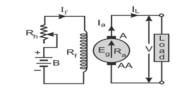
The flux produced by the poles depends upon the field current within the unsaturated region of the magnetic material of the poles — that is, \(\phi \propto I_f\) — but in the saturated region the flux remains constant.
If the contact brush drop per brush \(v_b\) is known,

The factor of two on the brush drop is not optional: the armature current passes through one brush on the way in and another on the way out, so both drops appear in series. Chapter 22 gave \(v_b \approx 1\) V for carbon brushes, making the total about 2 V — negligible in a 500 V machine, serious in a 24 V one.
Problem. A separately excited generator has a generated EMF of 250 V and delivers 60 A. The armature resistance is 0.15 \(\Omega\) and the brush drop is 1 V per brush. Find the terminal voltage, the power developed and the power output, and verify the loss balance.
Terminal voltage. Here \(I_a = I_L = 60\) A:
Powers.
Loss balance.
Comment. Note that the field loss does not appear here, because the field is supplied externally and its power comes from another source entirely. This is the one respect in which a separately excited machine flatters itself: its armature efficiency looks better than a shunt machine's, but only because someone else is paying for the excitation.
Self-Excited Generators
A DC generator whose field winding is excited by the current supplied by the generator itself is called a self-excited DC generator.
The field coils may be connected in parallel with the armature, in series with the armature, or partly in series and partly in parallel with the armature winding. Accordingly, self-excited generators are classified as:
Shunt wound generators
Series wound generators
Compound wound generators
A self-excited generator appears to face a chicken-and-egg problem: no field current means no flux, no flux means no EMF, and no EMF means no field current. The escape is residual magnetism — the iron of the poles retains a small flux from previous operation, as the hysteresis loop of Chapter 6 requires.
That residual flux generates a few volts, which drive a small field current, which strengthens the flux, which raises the EMF, and so on. The process is a positive feedback loop that settles where the magnetisation curve crosses the field-resistance line — and it fails altogether if the field resistance is too high or the residual flux has been lost. Chapter 28 treats voltage build-up and the critical resistance in full.
Shunt Wound Generators
In a shunt wound generator the field winding is connected across the armature winding, forming a parallel or shunt circuit, so that the full terminal voltage is applied across the field winding.
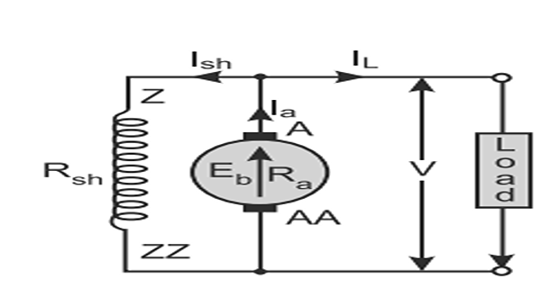
A very small current \(I_{sh}\) flows through it, because this winding has many turns of fine wire and therefore a very high resistance \(R_{sh}\) — of the order of 100 \(\Omega\).
\(I_{sh}\) is practically constant at all loads; therefore the DC shunt machine is considered to be a constant-flux machine.
Including brush contact drop,
The armature drop is set by the current actually flowing in the armature, and in a shunt generator that is \(I_L + I_{sh}\), not \(I_L\). Writing \(V = E_g - I R_a\) with an unqualified \(I\) invites exactly this error.
The difference is small — the field current is a few percent of the load — but it compounds, because \(I_{sh}\) itself depends on \(V\), so the equations are coupled and must be solved simultaneously. Example 26.2 shows how.

Problem. A shunt generator has a generated EMF of 240 V and delivers 100 A to the load. The armature resistance is 0.08 \(\Omega\), the shunt field resistance 120 \(\Omega\), and the brush drop 1 V per brush. Find the terminal voltage, the field and armature currents, and check the power balance.
Setting up. The terminal voltage is unknown and appears on both sides, since \(I_{sh}\) depends on it:
Solving. Collecting the \(V\) terms:
Currents.
Check: \(240 - (101.92)(0.08) - 2 = 240 - 8.15 - 2 = 229.85\) V \(\checkmark\)
Power balance.
Comment. Had the armature drop been computed with \(I_L = 100\) A instead of \(I_a = 101.92\) A, the terminal voltage would have come out as 230 V rather than 229.85 V — an error of only 0.07 %. Small here, but it grows with the field current, and in machines with a low armature resistance and a heavy field the discrepancy is quite visible. The habit of using \(I_a\) is worth forming.
Note also that the field consumes 440 W — 1.8 % of the developed power — which the separately excited machine of Example 26.1 charged to someone else.
Series Wound Generators
The field winding is connected in series with the armature winding, forming a series circuit, so that the full line current \(I_L\) — equal to the armature current \(I_a\) — flows through it.
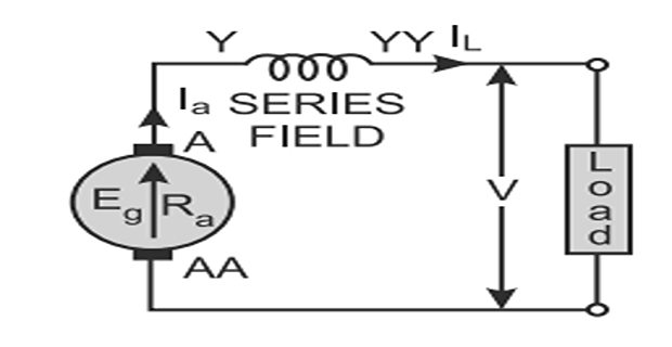
Since the series field winding carries the full-load current, it has a few turns of thick wire with low resistance — usually less than one ohm.
Including brush contact drop,
The flux developed by the series field winding is directly proportional to the current flowing through it, \(\phi \propto I_{se}\). But this is only true before magnetic saturation; after saturation the flux becomes constant even if the current through it is increased.
This single fact governs the whole behaviour of series machines. Below saturation, doubling the current doubles the flux and so quadruples the torque (Chapter 20); above it, the flux is fixed and the torque merely doubles.

Problem. A series generator has a generated EMF of 260 V while delivering 50 A. The armature resistance is 0.10 \(\Omega\), the series field resistance 0.08 \(\Omega\), and the brush drop 1 V per brush. Find the terminal voltage and check the losses.
Currents. There is only one path:
Terminal voltage.
Power and losses.
Comment. There is no separate field loss to account for, because the series field carries the load current and its \(I^{2}R\) is already included in the armature-circuit loss. This makes a series generator's bookkeeping the simplest of the four types — and its behaviour the most awkward, since the excitation vanishes when the load does.
Compound Wound Generators
There are two sets of field windings on each pole. One is connected in series, having a few turns of thick wire; the other is connected in parallel, having many turns of fine wire.
A compound wound generator may be long-shunt or short-shunt.
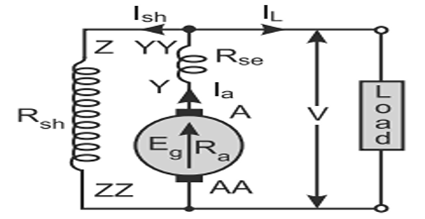
The shunt field winding is connected in parallel with the combination of both the armature and the series field winding.
Including brush contact drop,

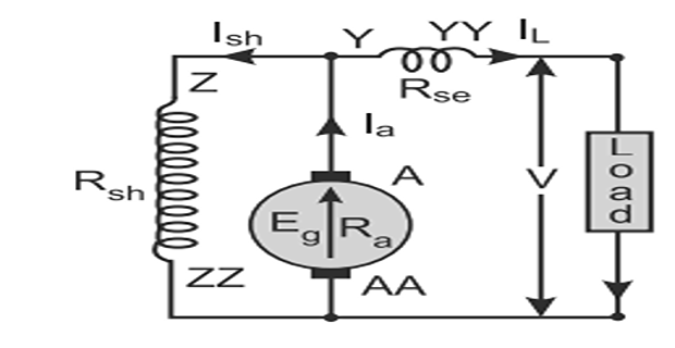
The shunt field winding is connected in parallel with the armature winding only.
Including brush contact drop,

Problem. A compound generator delivers 80 A at 220 V, with \(R_a = 0.10~\Omega\), \(R_{se} = 0.04~\Omega\), \(R_{sh} = 110~\Omega\) and a brush drop of 1 V per brush. Find the generated EMF for both connections.
(a) Long shunt. The shunt field sees the terminal voltage:
(b) Short shunt. The series field carries the load current:
Cross-check by the second route.
Comment. The two EMFs differ by only 0.08 V. As Chapter 20 noted, the distinction matters for the series winding, not for the EMF: it carries 82.0 A in long shunt but 80.0 A in short shunt, and a designer sizing that winding — or predicting how much the flux will boost at full load — must know which is used.
Cumulative and Differential Compounding
In compound wound DC generators, the field is produced by the shunt as well as the series winding. Generally the shunt field is stronger than the series field.
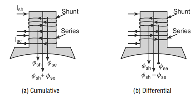
When the series field assists the shunt field, the generator is called cumulatively compound wound.
Flux rises with load, propping up the terminal voltage against the armature drop.
When the series field opposes the shunt field, the generator is known as differentially compound wound.
Flux falls with load, so the terminal voltage drops steeply — deliberately.
How much the series field boosts the flux depends on how many turns it has, and three cases are named:
Flat- or level-compounded: full-load voltage equals no-load voltage. Voltage regulation is zero.
Over-compounded: full-load voltage exceeds no-load voltage, compensating for the drop in a long feeder.
Under-compounded: full-load voltage is below no-load, but by less than a plain shunt machine.

Differential compounding sounds perverse until one asks what a drooping characteristic is good for. The answer is welding: a steeply falling voltage limits the current when the electrode touches the work, and stabilises the arc. Chapter 29 develops all these characteristics properly.
Problem. Three generators all give 250 V on no load. On full load they give 235 V, 250 V and 260 V respectively. Classify each and find its voltage regulation.
| Machine | \(V_{NL}\) | \(V_{FL}\) | Regulation | Classification |
|---|---|---|---|---|
| A | 250 V | 235 V | +6.38 % | Shunt or under-compounded |
| B | 250 V | 250 V | 0 % | Flat- or level-compounded |
| C | 250 V | 260 V | −3.85 % | Over-compounded |
Working for machine A.
Machine C.
Comment. A negative regulation looks like a mistake and is entirely deliberate. An over-compounded generator is designed to raise its voltage as it is loaded, so that the extra volts are consumed in the resistance of a long feeder and the load at the far end sees a constant voltage.
Machine B, flat-compounded, is the right choice when the load is close by. Machine A, a plain shunt machine, would need a field rheostat adjusted by hand — or an automatic voltage regulator — to hold its voltage as the load changes.
DC Motor Types
Every generator type has a motor counterpart, using the same machine with the same connections. Only two things change: the sign of the armature drop, and the fact that in a shunt motor the line current feeds both armature and field rather than the armature feeding the field.
| Type | Armature current (motor) | Back EMF | Generator form |
|---|---|---|---|
| Separately excited | \(I_a = I_L\) | \(E_b = V - I_aR_a\) | \(E_g = V + I_aR_a\) |
| Shunt | \(I_a = I_L - I_{sh}\) | \(E_b = V - I_aR_a\) | \(I_a = I_L + I_{sh}\) |
| Series | \(I_a = I_{se} = I_L\) | \(E_b = V - I_a(R_a + R_{se})\) | same currents |
| Compound, long shunt | \(I_a = I_L - I_{sh}\) | \(E_b = V - I_a(R_a + R_{se})\) | \(I_a = I_L + I_{sh}\) |
| Compound, short shunt | \(I_{se} = I_L\), \(I_a = I_L - I_{sh}\) | \(E_b = V - I_aR_a - I_LR_{se}\) | \(I_a = I_L + I_{sh}\) |
In every case the converted power is \(E_bI_a\) and the brush drop is subtracted as \(2v_b\), exactly as for the generator. Chapters 34 and 35 develop the torque and speed characteristics that follow.
Flux fixed by the terminal voltage, so \(T \propto I_a\) and the speed falls only slightly with load — typically 5 % from no load to full load.
Flux produced by the armature current, so \(T \propto I_a^{2}\) below saturation. Enormous starting torque, but the speed varies widely and it must never run unloaded.
Cumulative compound motors combine the two: the series field gives good starting torque while the shunt field guarantees a definite no-load speed, so the machine cannot run away. This is the standard choice wherever a heavy intermittent load must be started but the drive may also run light — presses, shears, rolling mills and lifts.
Applications
| Type | Characteristic | Applications |
|---|---|---|
| Permanent magnet | Constant flux, no excitation power | Automobile dynamos, tachogenerators, small portable sets |
| Separately excited | Flux under independent control; widest voltage range | Ward-Leonard drives, laboratory supplies, testing, electroplating |
| Shunt | Roughly constant voltage, drooping slightly | Battery charging, lighting, general-purpose supply, exciters |
| Series | Voltage rises steeply with load | Boosters on feeders, series arc lighting — rarely used alone |
| Cumulative compound (flat) | Zero regulation | Supply to a nearby load; the commonest compound machine |
| Cumulative compound (over) | Negative regulation | Feeding a load at the end of a long line, railway supply |
| Differential compound | Steeply drooping | Arc welding, where current must self-limit |
| Type | Characteristic | Applications |
|---|---|---|
| Separately excited | Precise, independent speed and torque control | Ward-Leonard drives, rolling mills, paper machines, servo drives |
| Shunt | Nearly constant speed; \(T \propto I_a\) | Lathes, blowers, centrifugal pumps, fans, conveyors, machine tools |
| Series | Very high starting torque; \(T \propto I_a^{2}\) | Traction, cranes, hoists, trolleys, starters, winches |
| Cumulative compound | High starting torque with a safe no-load speed | Presses, shears, punches, rolling mills, lifts, reciprocating pumps |
| Differential compound | Nearly constant speed but unstable | Rarely used |
Summary and Key Formulas
DC generators are classified by their method of field excitation: permanent magnet, separately excited, or self-excited as shunt, series or compound.
Permanent-magnet machines are compact with a constant field, but the magnet flux deteriorates with time and cannot be adjusted.
Separately excited: \(I_a = I_L\), \(V = E_g - I_aR_a - 2v_b\). Flux under independent control, with \(\phi \propto I_f\) below saturation.
Self-excited machines rely on residual magnetism to start building up.
Shunt: \(I_{sh} = V/R_{sh}\) (small, so a constant-flux machine), \(I_a = I_L + I_{sh}\), and the drop uses \(I_a\) — not \(I_L\).
Series: \(I_a = I_{se} = I_L\), \(V = E_g - I_a(R_a + R_{se}) - 2v_b\). Flux \(\propto I_{se}\) only below saturation.
Compound, long shunt: \(I_{sh} = V/R_{sh}\), series field carries \(I_a\). Short shunt: series field carries \(I_L\) and \(I_{sh} = (V + I_LR_{se})/R_{sh} = (E_g - I_aR_a)/R_{sh}\).
Cumulative compounding has the series field assisting the shunt field; differential has it opposing. Cumulative machines may be flat, over- or under-compounded.
Motors use the same connections with \(E_b = V - I_aR_a\) and, for a shunt motor, \(I_a = I_L - I_{sh}\).
Series motors for traction and hoists; shunt for constant speed; cumulative compound where both are needed.
| Type | Field current | Armature current | Terminal voltage |
|---|---|---|---|
| Separately excited | External | \(I_a = I_L\) | \(V = E_g - I_aR_a - 2v_b\) |
| Shunt | \(I_{sh} = V/R_{sh}\) | \(I_a = I_L + I_{sh}\) | \(V = E_g - I_aR_a - 2v_b\) |
| Series | \(I_{se} = I_a\) | \(I_a = I_L\) | \(V = E_g - I_a(R_a + R_{se}) - 2v_b\) |
| Long shunt | \(I_{sh} = V/R_{sh}\) | \(I_a = I_L + I_{sh}\) | \(V = E_g - I_a(R_a + R_{se}) - 2v_b\) |
| Short shunt | \(I_{sh} = \dfrac{V + I_LR_{se}}{R_{sh}}\) | \(I_a = I_L + I_{sh}\) | \(V = E_g - I_aR_a - I_LR_{se} - 2v_b\) |
| Power developed | \(P_{\text{dev}} = E_gI_a\) | ||
| Power output | \(P_{\text{out}} = VI_L\) | ||
| Voltage regulation | \(\dfrac{V_{NL} - V_{FL}}{V_{FL}} \times 100\,\%\) | ||
Common Mistakes
Writing the armature drop as \(I_LR_a\) in a shunt machine. It is \(I_aR_a\), and \(I_a = I_L + I_{sh}\) in a generator.
Forgetting that the shunt equations are coupled. \(I_{sh}\) depends on \(V\), which depends on \(I_a\), which depends on \(I_{sh}\) — solve simultaneously.
Using one brush drop instead of two. The current passes through a brush at each end, so the total is \(2v_b\).
Applying the terminal voltage to a short-shunt field. There the field sees \(V + I_LR_{se}\).
Putting \(I_a\) through the series field of a short-shunt machine. It carries \(I_L\); only in long shunt does it carry \(I_a\).
Assuming \(\phi \propto I\) always. True only below saturation; beyond it the flux is essentially constant.
Counting the field loss twice in a series machine. The series-field \(I^{2}R\) is already inside \(I_a^{2}(R_a + R_{se})\).
Treating a negative voltage regulation as an error. Over-compounded machines are designed for it.
Keeping the generator current relation for a motor. A shunt motor has \(I_a = I_L - I_{sh}\).
Expecting a permanent-magnet machine to hold its rating for ever. The magnets weaken with time, and there is no field rheostat to compensate.
Chapter Review
Identify the type and the connection first, then write the field current, then the armature current, then the voltage — in that order, every time.
P26.1 A separately excited generator has \(E_g = 300\) V and delivers 75 A with \(R_a = 0.20~\Omega\) and 1 V per brush. Find \(V\) and the output power.
Show answer
\[V = 300 - (75)(0.20) - 2 = 300 - 15 - 2 = 283~\mathrm{V}\]\[P_{\text{out}} = (283)(75) = 21\,225~\mathrm{W}\]P26.2 A shunt generator delivers 60 A at a terminal voltage of 200 V, with \(R_a = 0.12~\Omega\), \(R_{sh} = 100~\Omega\) and 1 V per brush. Find \(E_g\).
Show answer
\[I_{sh} = \frac{200}{100} = 2.00~\mathrm{A}, \qquad I_a = 60 + 2.00 = 62.0~\mathrm{A}\]Here \(V\) is given, so no simultaneous solution is needed — a useful simplification worth spotting.\[E_g = V + I_aR_a + 2v_b = 200 + (62.0)(0.12) + 2 = 200 + 7.44 + 2 = 209.4~\mathrm{V}\]P26.3 A shunt generator has \(E_g = 260\) V and delivers 120 A, with \(R_a = 0.05~\Omega\), \(R_{sh} = 130~\Omega\) and 1 V per brush. Find \(V\).
Show answer
Now \(V\) is unknown and the equations are coupled:\[V\left(1 + \frac{0.05}{130}\right) = 260 - (120)(0.05) - 2 = 252\]\[V = \frac{252}{1.000385} = 251.90~\mathrm{V}\]\[I_{sh} = \frac{251.90}{130} = 1.938~\mathrm{A}, \qquad I_a = 121.94~\mathrm{A}\]P26.4 A series generator delivers 40 A at 230 V with \(R_a = 0.14~\Omega\), \(R_{se} = 0.06~\Omega\) and 1 V per brush. Find \(E_g\) and the developed power.
Show answer
\[E_g = 230 + (40)(0.20) + 2 = 230 + 8 + 2 = 240~\mathrm{V}\]\[P_{\text{dev}} = (240)(40) = 9600~\mathrm{W}\]P26.5 A long-shunt compound generator delivers 100 A at 250 V, with \(R_a = 0.08~\Omega\), \(R_{se} = 0.03~\Omega\), \(R_{sh} = 125~\Omega\) and 1 V per brush. Find \(E_g\).
Show answer
\[I_{sh} = \frac{250}{125} = 2.00~\mathrm{A}, \qquad I_a = 102.0~\mathrm{A}\]\[E_g = 250 + (102.0)(0.11) + 2 = 250 + 11.22 + 2 = 263.2~\mathrm{V}\]P26.6 Repeat P26.5 for a short-shunt connection.
Show answer
\[I_LR_{se} = (100)(0.03) = 3.00~\mathrm{V}, \qquad I_{sh} = \frac{250 + 3.00}{125} = 2.024~\mathrm{A}\]\[I_a = 102.02~\mathrm{A}\]Practically identical to P26.5, but the series field carries 100 A rather than 102 A.\[E_g = 250 + (102.02)(0.08) + 3.00 + 2 = 250 + 8.162 + 3.00 + 2 = 263.2~\mathrm{V}\]P26.7 A generator gives 240 V on no load and 228 V on full load. Find the regulation and classify it.
Show answer
Positive regulation, so the machine is a shunt or under-compounded generator.\[\frac{240 - 228}{228} \times 100 = \frac{12}{228} \times 100 = 5.26\,\%\]P26.8 A 220 V shunt motor takes 45 A from the line, with \(R_{sh} = 110~\Omega\), \(R_a = 0.15~\Omega\) and 1 V per brush. Find \(I_a\), the back EMF and the converted power.
Show answer
For a motor the line current splits:\[I_{sh} = \frac{220}{110} = 2.00~\mathrm{A}, \qquad I_a = I_L - I_{sh} = 45 - 2.00 = 43.0~\mathrm{A}\]\[E_b = 220 - (43.0)(0.15) - 2 = 220 - 6.45 - 2 = 211.55~\mathrm{V}\]\[P_{\text{conv}} = E_bI_a = (211.55)(43.0) = 9097~\mathrm{W}\]P26.9 Which generator type would you choose to feed a load at the end of a long cable, and why?
Show answer
An over-compounded cumulative generator. Its terminal voltage rises as the load increases, and that rise is designed to match the \(IR\) drop in the cable.The result is that the voltage at the far end — where the load actually is — stays constant, even though the generator terminals do not. A flat-compounded machine would hold its own terminals constant and let the far end sag, which is not what the customer cares about.
P26.10 Why is a series motor unsuitable for a lathe, and a shunt motor unsuitable for a crane hoist?
Show answer
Series motor on a lathe: a lathe needs a definite, nearly constant speed for a given cut, and it is often run with little load while setting up. A series motor's speed varies steeply with load and it races dangerously when unloaded, since \(N \propto 1/\phi\) and \(\phi \propto I_a\).Shunt motor on a hoist: a hoist must break a heavy load away from rest. A shunt motor gives only \(T \propto I_a\), so reaching the required starting torque means drawing a very large current — whereas a series motor's \(T \propto I_a^{2}\) delivers the same torque for far less.
A cumulative compound motor serves both duties, which is why it is so common on cranes: series torque for starting, shunt field for a safe no-load speed.
MCQ 1. DC generators are classified according to:
(a) the winding type (b) the method of field excitation (c) the number of poles (d) the brush materialShow answer
(b) the method of field excitation.MCQ 2. The main disadvantage of a permanent-magnet generator is that:
(a) it needs excitation power (b) the magnet flux deteriorates with time (c) it cannot be made compact (d) it has no commutatorShow answer
(b) the magnet flux deteriorates with time, changing the machine's characteristics — and there is no field winding with which to compensate.MCQ 3. In a shunt generator the armature current is:
(a) \(I_L\) (b) \(I_L - I_{sh}\) (c) \(I_L + I_{sh}\) (d) \(I_{sh}\)Show answer
(c) \(I_L + I_{sh}\) — the armature feeds the load and its own field.MCQ 4. The shunt field winding has:
(a) few turns of thick wire (b) many turns of fine wire (c) no turns (d) the same as the series fieldShow answer
(b) many turns of fine wire, giving a resistance of the order of 100 \(\Omega\).MCQ 5. The brush contact drop appearing in the terminal voltage equation is:
(a) \(v_b\) (b) \(2v_b\) (c) \(v_b/2\) (d) \(4v_b\)Show answer
(b) \(2v_b\), since the current passes through a brush at each end of the armature circuit.MCQ 6. In a short-shunt compound generator, the series field carries:
(a) \(I_a\) (b) \(I_L\) (c) \(I_{sh}\) (d) zeroShow answer
(b) \(I_L\). In long shunt it carries \(I_a\).MCQ 7. When the series field assists the shunt field, the machine is:
(a) differentially compounded (b) cumulatively compounded (c) separately excited (d) under-excitedShow answer
(b) cumulatively compounded.MCQ 8. A flat-compounded generator has a voltage regulation of:
(a) zero (b) positive (c) negative (d) infiniteShow answer
(a) zero — full-load voltage equals no-load voltage.MCQ 9. A differentially compounded generator is used for:
(a) battery charging (b) arc welding (c) lighting (d) tractionShow answer
(b) arc welding, where the steeply drooping characteristic limits the current when the electrode touches the work.MCQ 10. The motor type with the highest starting torque for a given current is:
(a) shunt (b) series (c) separately excited (d) differential compoundShow answer
(b) series, since \(T \propto I_a^{2}\) below saturation.
Classify DC generators by field excitation and state the defining feature of each class.
Give the advantages and the principal disadvantage of a permanent-magnet generator.
Write the complete set of relations for a shunt generator, explaining why the equations are coupled.
Explain how a self-excited generator builds up its voltage, and what it depends on.
Contrast the construction and the behaviour of the shunt and series field windings.
Distinguish long-shunt from short-shunt and derive the field current in each case.
Explain cumulative and differential compounding, and the flat, over- and under-compounded characteristics.
Explain how the motor equations differ from the generator ones, and why.
Every type is now defined with its circuit equations. Chapter 27 supplies the quantity they all depend on — the EMF equation of a DC generator, \(E_g = \Phi PNZ/60A\) — applied to design problems, with the parallel-path count \(A\) from Chapter 25.
Chapter 28 takes up the voltage build-up sketched in Section 26-4: the magnetisation curve, the field-resistance line, the critical field resistance above which a self-excited machine will not build up at all, and the critical speed below which it likewise fails.
Chapter 29 then plots the characteristics of every generator in this chapter — the open-circuit, internal and external characteristics — and shows precisely why the shunt machine droops, the series machine rises, and the compound machine can be made to do either.