Rectifier Diodes
Used in low-frequency power supplies
Optimized for 60 Hz
Power rating: \(>\) 0.5 W
Forward current rating: Amperes
Limited use outside power supplies
Small-Signal Diodes
Optimized for high frequencies
Power rating: \(<\) 0.5 W
Current rating: Milliamperes
Smaller and lighter construction
The Positive Clipper
Removes positive parts of waveform
Useful for signal shaping, protection, communications
- Positive clipper circuit
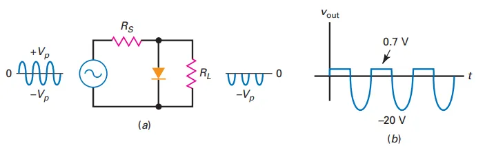
During positive half-cycle: Diode conducts, output voltage \(\approx\) 0 V
During negative half-cycle: Diode is open, negative half-cycle appears at output
Series resistor much smaller than load resistor
Output peak: \(2V_p\) (Fig.(a))
Diode voltage when conducting: 0.7 V
Clipping level: 0.7 V, not zero
Example: Input signal peak of 20 V results in output
The Negative Clipper
- Reversed Diode Polarity
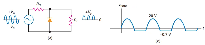
Removes negative parts of the signal
Output waveform ideally has only positive half-cycles
Imperfect Clipping: Due to diode offset voltage (barrier potential)
Clipping level: \(20.7\) V
For input signal peak of \(20\) V, output signal shown in Fig.(b)
- Reversed Diode Polarity
The Limiter or Diode Clamp
Normal Operation:
Input: Peak at 15 mV
Output: Same signal (Diodes off)
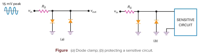
Purpose of the Circuit:
Protection: Limits input signal to protect sensitive circuits
Positive-Negative Limiter:
Limits output to 0.7 V if input exceeds 0.7 V
Limits output to -0.7 V if input drops below -0.7 V
Examples of Sensitive Circuits:
Op Amp:
Normal input \(<\) 15 mV
Voltages \(>\) 0.7 V are abnormal
Limiter prevents excessive voltage
Moving-Coil Meter:
Limiter protects against excessive voltage/current
Diode Clamp:
Function: Clamps/limits voltage to a specified range
Operation: Diodes conduct only during abnormal conditions (signal too large)
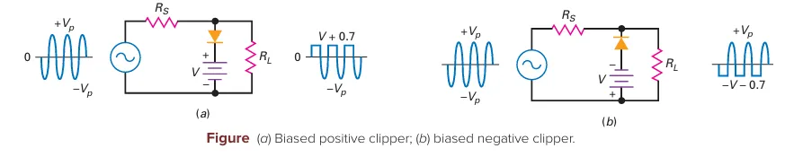
Biased Clippers
Reference Level:
Positive Clipper: Ideally 0 V or 0.7 V
Changing Reference Level:
Biasing: Apply external voltage to shift reference level
Positive Biased Clipper:
Add a DC voltage source in series with the diode
New reference voltage (\(V\)) must be less than peak voltage (\(V_p\))
Ideal Diode: Conduction starts when input \(> V\)
Second Approximation: Conduction starts when input \(> V + 0.7\) V
Negative Biased Clipper:
Reverse diode and battery
Reference level changes to \(-V - 0.7\) V
Output waveform negatively clipped at the bias level
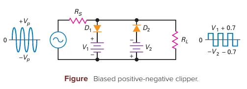
Combining Biased Clippers
Configuration:
Diode \(D_1\): Clips positive parts above the positive bias level
Diode \(D_2\): Clips negative parts below the negative bias level
Output Signal:
When input voltage is much larger than bias levels
Output is a square wave
Signal Shaping:
Clippers enable shaping signals into specific waveforms
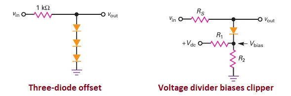
Setting the Clipping Level Without Batteries
Using Silicon Diodes:
Each diode produces a bias of 0.7 V
Example: Three diodes produce a clipping level of \(\approx 2.1\) V
Application: Can act as a diode clamp (limiting) to protect sensitive circuits
Using a Voltage Divider:
Configuration: \(R_1\) and \(R_2\) set the bias level
Bias Level:
Output is clipped when input \(> V_{\text{bias}} + 0.7\) V
Biased Diode Clamp:
Example: Bias level set to +5 V
Protects against large input voltages (e.g., +100 V)
Output limited to +5.7 V
Removing Offset:
Variation: Bias diode \(D_2\) into slight forward conduction
This puts diode \(D_1\) on the verge of conduction
Result: Diode \(D_1\) conducts near 0 V, minimizing offset
