Produces DC output equal to peak value of rectified voltage
Most widely used in power supplies
Circuit Components: AC source, Diode, and Capacitor
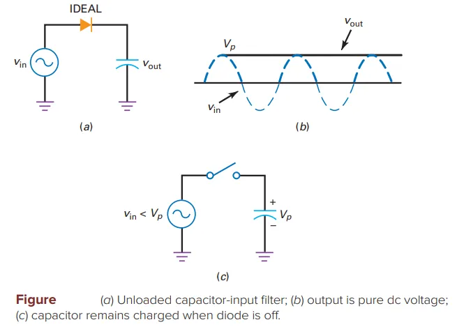
Operation:
Initially, capacitor is uncharged
During first quarter-cycle:
Diode forward biased, capacitor charges
Voltage across capacitor = Source voltage
Capacitor voltage = \(V_p\) (peak voltage)
After peak, diode turns off:
Capacitor stays charged
Output voltage = \(V_p\) (constant)
With Load Resistor:
Connect across capacitor
Capacitor remains charged if \(RLC\) time constant \(\gg\) period
Output voltage \(\approx V_p\) with small ripple
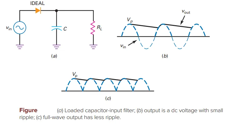
Ripple:
Diode off between peaks, capacitor discharges through load resistor
Capacitor supplies load current
Peak-to-peak ripple is small
Diode recharges capacitor to peak voltage when next peak arrives
Full-Wave or Bridge Rectifier:
Reduces peak-to-peak ripple by half
Capacitor discharges for half the time compared to half-wave rectifier
Ripple Formula:
\(V_R\) = Peak-to-peak ripple voltage
\(I\) = DC load current
\(f\) = Ripple frequency
\(C\) = Capacitance
Usage:
Approximation, not exact
Accurate results require circuit simulation (e.g., Multisim)
Given:
DC load current = 10 mA
Capacitance = 200 \(\mu\)F
Ripple frequency (bridge rectifier) = 120 Hz
- Ripple Calculation:\[V_R = \frac{10 \text{ mA}}{120 \text{ Hz} \times 200 \mathrm{ \mu F}} = 0.417 \text{ V}_{\text{p-p}}\]
Measurement Methods:
Use oscilloscope for accurate measurement
AC voltmeter may introduce error (up to 25%)
Conversion:
Converts peak-to-peak value to rms value
Factors Affecting DC Load Voltage:
Diode drops (subtract from peak voltage)
Additional voltage drop due to:
Heavy diode conduction during brief periods
Transformer winding and diode bulk resistance
Calculation:
Ideal output or output with diode approximation
Actual DC voltage is slightly lower
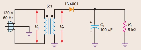
Problem: Half-wave rectifier and capacitor-input filter
What is the dc load voltage and ripple?
Problem: Full-wave rectifier and capacitor-input filter
What is the dc load voltage and ripple?
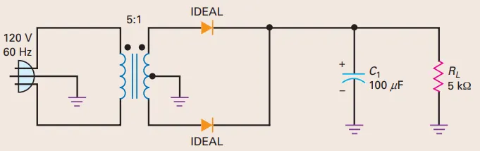
Transformer: \(5:1\) step-down
Peak secondary voltage: 34 V (previous problem)
Input to each halfwave section: 34 V / 2 = 17 V
DC load voltage (ideal diode, small ripple): 17 V
Problem: Bridge rectifier and capacitor-input filter
What is the dc load voltage and ripple?
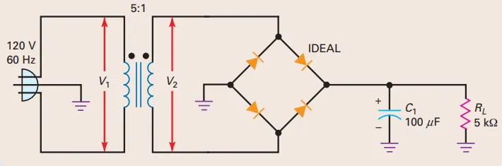
Comparison & Conclusion:
Bridge rectifier vs. half-wave rectifier: less ripple
Bridge rectifier vs. full-wave rectifier: twice the output voltage
Bridge rectifier: most popular