Lecture 6D — Scope and Objectives
- Phase control: \(\eta \leq (1-s)\); simple but fundamentally inefficient at low speed.
- Power factor degrades with \(\alpha\); mitigation via line reactors, 12-pulse topology, or passive filters.
- SER drive: \(T_e = K_t I_{dc}\); returns \(sP_{ag}\) to the supply.
- SER efficiency \(> 85\,\%\) even at \(60\,\%\) speed.
- Converter rated at only \(s_{\max}\) fraction of motor power — economical for limited speed ranges.
- Historical context: Kramer and Scherbius drives
- Static Scherbius drive: bidirectional converter, four-quadrant capability
- Supersynchronous operation explained
- Industrial application: large pump drives and affinity laws
- Wind energy: DFIG concept, MPPT and reactive power control
- Unified comparison: all three drive types side by side
Historical Context — Kramer and Scherbius Drives
- Rotor slip rings connected to a rotary converter (motor–generator set).
- The DC motor of the set was mechanically coupled back to the induction motor shaft — slip energy returned mechanically to increase shaft output.
- Very large, heavy, with low overall efficiency due to the two machine stages.
- Only subsynchronous motoring possible.
- Slip rings connected to a commutator (Scherbius) machine that fed power back to the AC supply electrically.
- More flexible: speed range could span both sub- and supersynchronous operation.
- Still required large rotating machines.
| Classical Drive | Modern Static Equivalent |
|---|---|
| Kramer | SER drive (diode bridge + SCR inverter) |
| Scherbius | Static Scherbius drive (back-to-back VSC) |
- No rotating converter machines; higher efficiency, smaller footprint.
- Fully controllable dynamic response.
- Modern DFIG wind turbines are the contemporary manifestation of the Scherbius principle.
Static Scherbius Drive — Four-Quadrant Operation
SER limitation: The diode-bridge rectifier is unidirectional \(\Rightarrow\) slip power can only flow out of the rotor, so only subsynchronous motoring is possible (\(s > 0\)).
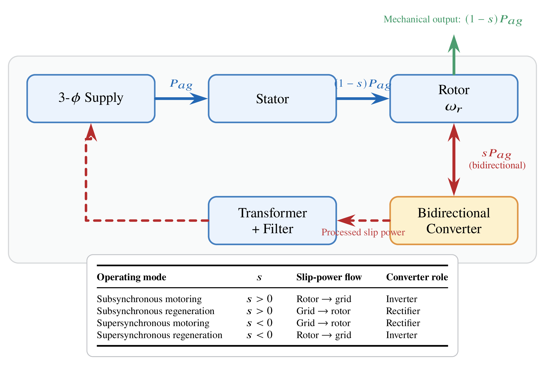
Scherbius drive: Replace the diode bridge with a bidirectional (back-to-back) converter, allowing slip power to flow in either direction.
Power balance in all modes:
When \(s < 0\) (supersynchronous), \(sP_{ag} < 0\): power is injected into the rotor from the converter, supplementing shaft output.
Bidirectional converter options:
- Cycloconverter: anti-parallel 3-phase bridge sets; line-commutated; suited to very large power levels.
- PWM back-to-back VSC: modern standard; sinusoidal currents; near-unity supply power factor.
Advantages: True four-quadrant operation · High efficiency across full speed range · Converter rated at only \(s_{\max}\) of motor power · Compact and cost-effective at MW scale.
Supersynchronous Operation — Power Flow
When the rotor spins faster than synchronous speed, slip is negative:
A negative value means power is being injected into the rotor from the converter, augmenting the mechanical output.
Supersynchronous motoring (\(s < 0\)):
- Mechanical output: \(P_{\text{mech}} = (1-s)P_{ag} > P_{ag}\).
- Both stator and rotor converter supply power to the shaft.
- The rotor-side converter operates as a rectifier (power flows into the rotor from the supply).
| Mode | \(s\) | \(sP_{ag}\) Direction | Rotor Converter |
|---|---|---|---|
| Subsync. motoring | \(+\) | out of rotor | Inverter |
| Subsync. regen.* | \(-\) | into rotor | Rectifier |
| Supersync. motoring | \(-\) | into rotor | Rectifier |
| Supersync. regen. | \(-\) | out of rotor | Inverter |
* subsync. regen.: \(0 < s < 1\) but machine acts as a generator (braking).
Key insight: In supersynchronous generation (e.g. wind above synchronous speed), both stator and rotor deliver electrical power simultaneously. Total generation \(= P_{ag} + |s|\,P_{ag} = (1+|s|)\,P_{ag}\).
Application: Large Industrial Pump Drives
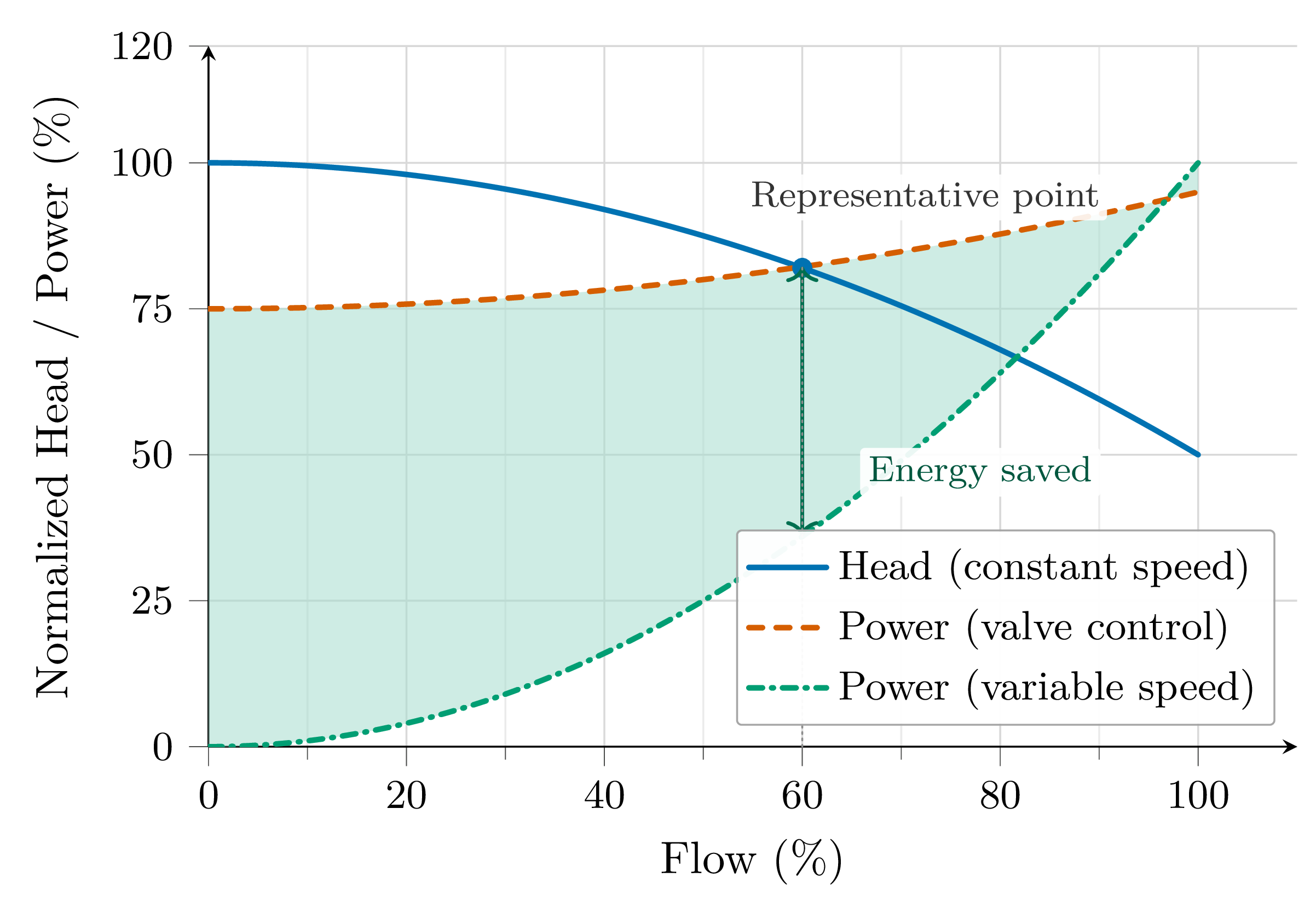
Conventional flow control — throttle valve:
- Pump runs at constant speed; flow reduced by partially closing the discharge valve.
- Energy wasted as pressure drop across the valve — highly inefficient at reduced flow.
Variable-speed drive — pump affinity laws:
A 20% speed reduction cuts shaft power to \((0.8)^3 \approx 51\,\%\) of full-speed power — a 49% saving.
Typical large installation: Ratings 9.5 MW and 11.5 MW · Speed ranges 757–1165 rpm / 1135–1745 rpm · Supply voltage 13.8 kV · Dual series-connected 3-phase SCR bridges · Liquid-cooled auxiliary starting resistors · Flow range 60–100% \(\Rightarrow\) converter rated at \(\approx 30\,\%\) of motor power.
Application: Wind Energy Conversion — DFIG Concept
The wound-rotor IM operating as a generator with bidirectional slip-energy exchange is the basis of the doubly-fed induction generator (DFIG), the dominant technology in grid-connected wind turbines above 1 MW.
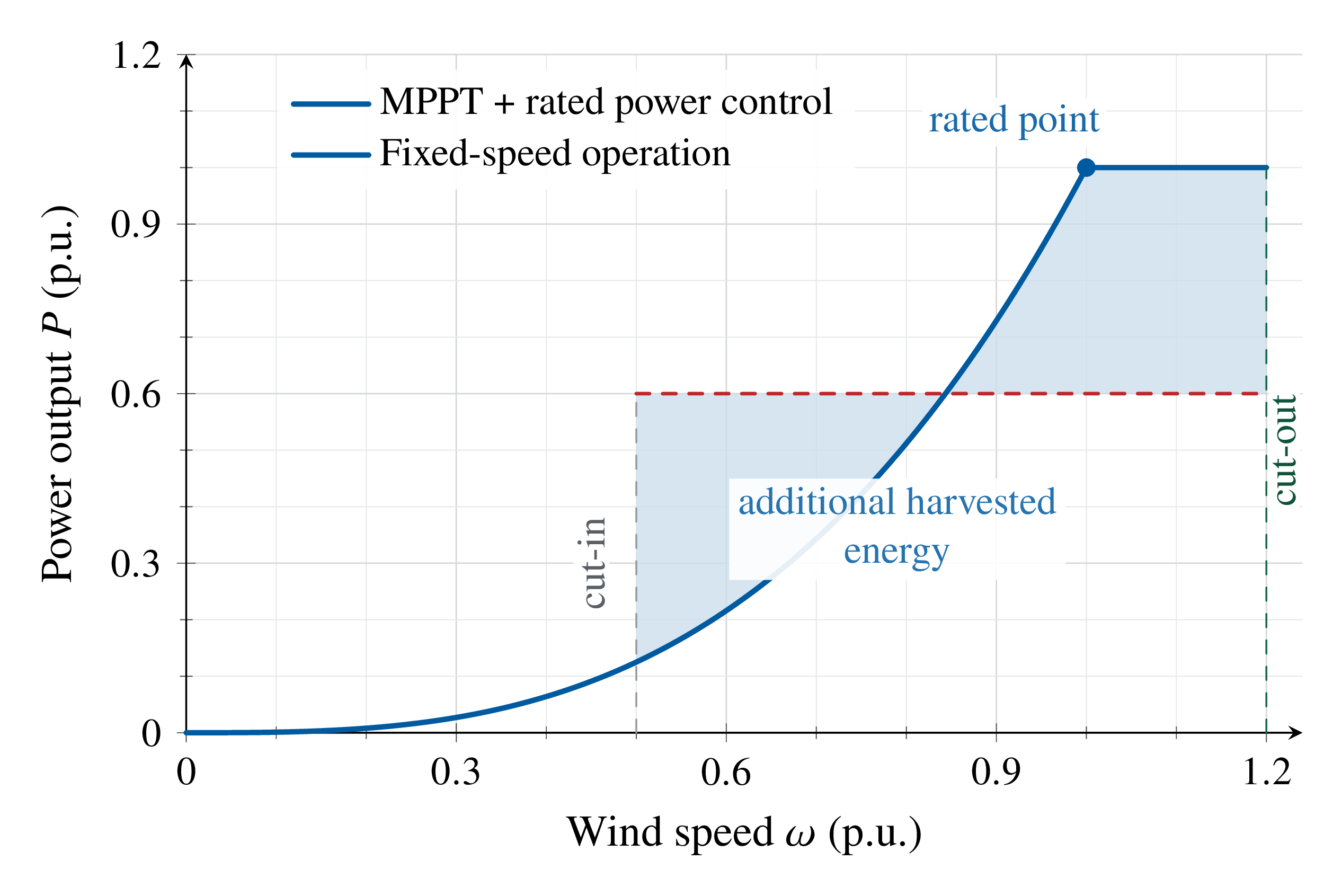
Why variable speed matters:
- Wind speed varies continuously; to maximise aerodynamic efficiency, rotor speed must track the wind (\(C_P\) optimisation).
- Maximum Power Point Tracking (MPPT): \(P_{\text{aero}} \propto \omega_r^3\).
- Fixed-speed machines waste energy whenever wind speed differs from the design point.
Key difference from pump drives: In wind turbines the speed range spans \(\approx \pm 30\,\%\) around synchronous speed (both sub- and supersynchronous generation). The bidirectional converter handles the full slip-power band in both directions.
DFIG — Reactive Power Control Capability
The rotor-side converter of a modern DFIG controls both the active power (via torque) and the reactive power delivered by the stator to the grid — independently.
How reactive power is controlled:
In rotor flux-oriented (vector) control, the rotor current is decomposed into two orthogonal components:
- \(i_{rq}\): component in quadrature with rotor flux \(\Rightarrow\) controls electromagnetic torque.
- \(i_{rd}\): component in phase with rotor flux \(\Rightarrow\) controls magnetising current and stator reactive power.
- Increasing \(i_{rd}\) causes the stator to export reactive power (capacitive — voltage support).
- Decreasing \(i_{rd}\) causes the stator to absorb reactive power (inductive).
Reactive power operating range:
independently of active power output, subject to rotor converter current rating. Unity power factor at the stator terminals is achievable at any wind speed.
Grid-code requirement: Modern grid codes require wind farms to provide dynamic reactive power support during voltage disturbances (fault ride-through, FRT). The DFIG's independent \(P\)–\(Q\) control is what enables FRT compliance — a squirrel-cage generator cannot do this without a full-rated reactive compensator.
Comparative Summary — All Three Drive Types
| Feature | Stator Resistance Control | Phase (SCR) Control | Slip-Energy Recovery |
|---|---|---|---|
| Control variable | External \(R_{\text{ext}}\) | Firing angle \(\alpha\) | Firing angle \(\alpha\) (rotor back-EMF) |
| Efficiency at low speed | Very poor (\(\ll 1{-}s\)) | Poor (\(\approx 1{-}s\)) | High (\(> 85\,\%\) typical) |
| Input power factor | Moderate | Poor (degrades with \(\alpha\)) | Good (VSC version: unity) |
| Rotor type | Squirrel-cage or wound | Squirrel-cage | Wound-rotor (slip rings) |
| Converter cost | Very low | Low | Moderate |
| Quadrant operation | 1 | 1 or 3 (reversible ctrl.) | 1 basic; 4 with Scherbius |
| Harmonic content | Low | Moderate | Moderate (6th harmonic) |
| Supply harmonics | Low | Moderate | Moderate (12-pulse mitigates) |
| Controller complexity | Simple | Moderate | Moderate (DC-drive-like) |
| Typical applications | Starting resistor only | Fans, pumps, soft-starters | Large pumps, MW-scale wind |
Key Takeaways — Complete Lecture Series
- Air-gap power partition: rotor copper loss \(= s\,P_{ag}\); ceiling \(\eta\leq(1-s)\) is fundamental.
- SCR waveforms non-sinusoidal for \(\alpha>\phi\); harmonics govern thermal rating.
- Input power factor degrades with \(\alpha\); mitigation essential in large drives.
- Stability: operating point must lie on the low-slip side of peak torque.
- Open-loop speed range \(\approx 6\,\%\); closed-loop cascade control mandatory.
- NEMA D motors extend the stable region.
- Returns \(sP_{ag}\) to supply — breaks the \((1-s)\) efficiency barrier.
- \(T_e \propto I_{dc}\): single-variable control (DC-drive analogy).
- Converter cost \(\propto s_{\max}\): economic only for limited speed ranges (\(\leq 30\,\%\)).
- Supply harmonics mitigated by 12-pulse topology or line reactors.
- Static Scherbius extends to four-quadrant sub- and supersynchronous operation.
- Modern DFIG adds independent reactive power control for grid support and fault ride-through.
"The recovery of slip energy transforms the induction machine from a variable-speed workhorse into a high-efficiency, controllable industrial drive system."
Both schemes remain cost-effective for large wound-rotor IM systems where the required speed range is limited (\(\leq 30\,\%\) of rated speed), where a full-rated PWM-inverter drive would be disproportionately expensive.