Lecture 6B — Scope and Objectives
- Air-gap power partition: rotor copper loss \(= s\,P_{ag}\); ceiling \(\eta\leq(1-s)\).
- SCR waveforms: non-sinusoidal for \(\alpha>\phi\); harmonics worsen with \(\alpha\).
- Firing angle \(\alpha\) reduces rms stator voltage; control only for \(\alpha > \phi\).
- Stability criterion: operating point must lie to the right of peak torque (low-slip side).
- Conduction angle \(\beta\): transcendental equation (Newton–Raphson).
- Open-loop speed range \(\approx 6\,\%\) for fan load.
- Load torque models and rotor current profile vs. speed
- Stator current vs. speed: thermal design
- Input power factor and reactive power of the phase-controlled drive
- Closed-loop cascade PI controller design
- Efficiency: phase control vs. external resistance
- Practical drive applications
- Transition: SER principle and power circuit
Load Torque Models and Rotor Current Profile
| \(k\) | Load Type |
|---|---|
| \(0\) | Constant torque (press, crane hoist) |
| \(1\) | Viscous (linear) friction |
| \(2\) | Centrifugal load (pump, fan) |
Rotor current at each operating point — using the approximation \(I_r \propto T_e / \omega_r\) at low slip:
| Load Type | \(I_{r,\max}\) Slip | Relative Magnitude |
|---|---|---|
| \(k=1\) (viscous) | \(s = 1/3\) | intermediate |
| \(k=2\) (pump/fan) | \(s = 1/5\) | lower |
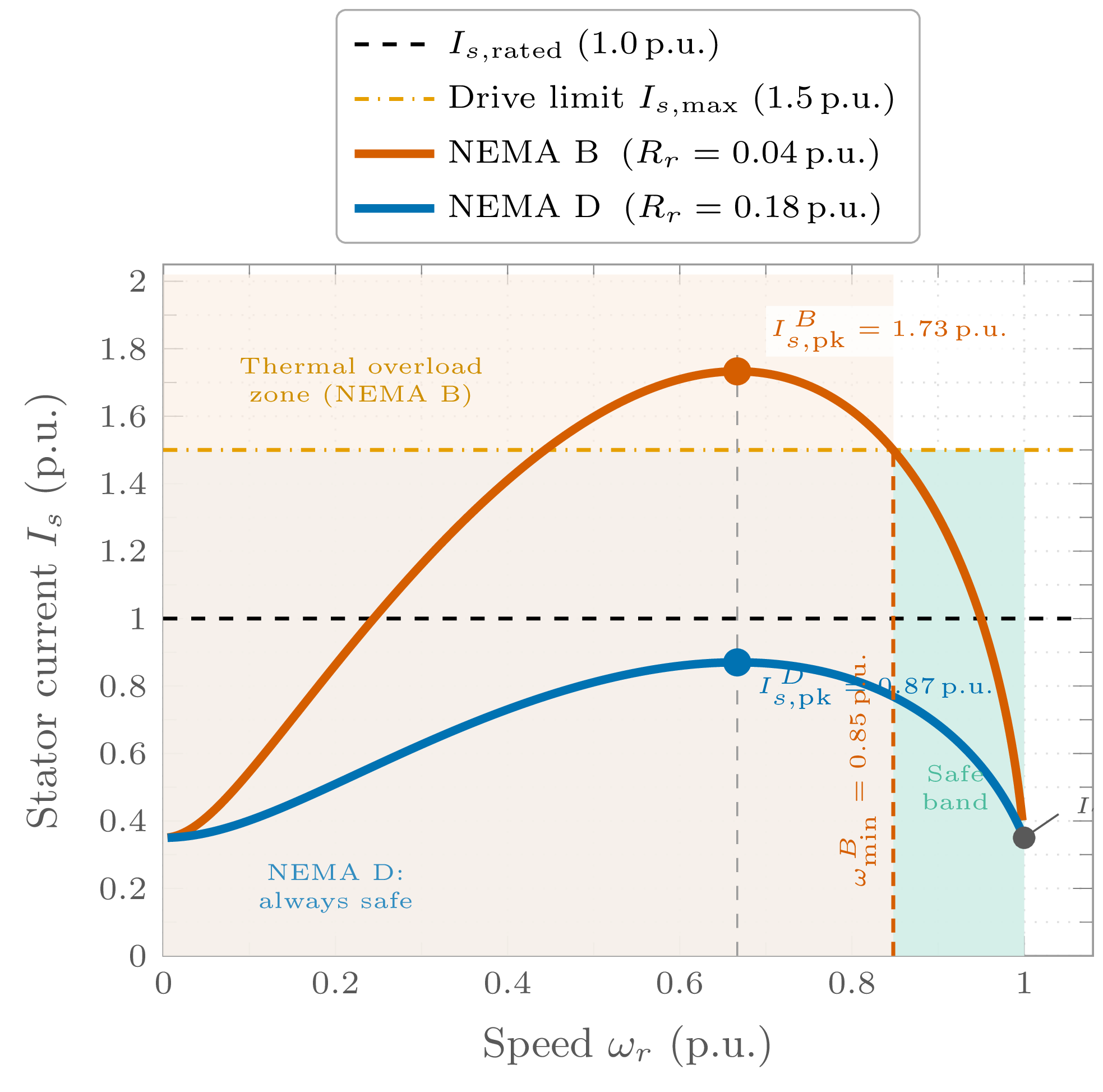
Stator current (phasor sum):
Key design implication: Peak stator current occurs at an intermediate speed, not at standstill. The current limiter must be set at or below this peak to protect motor windings and SCR devices.
Thermal constraint: Phase control introduces harmonic currents that produce additional winding losses with no useful average torque. The rms stator current — not its fundamental alone — governs the thermal rating.
Thermal Limits and NEMA D Motor Selection
- The region where \(I_s \leq I_{s,\max}\) defines the safe operating band.
- Below a minimum speed, \(I_s\) rises back above the limit even under closed-loop control; the drive must not be operated below \(\omega_{\min}\).
- Typical usable range: 70–100% of synchronous speed (dependent on load type).
NEMA D motor advantage:
- High \(R_r\) \(\Rightarrow\) peak torque near \(s \approx 1\) (near standstill).
- Larger stable region on the torque–speed curve.
- Peak rotor current reduced and occurs at lower speed.
- Trade-off: higher rotor \(I^2R\) losses at full load; lower full-load efficiency compared with NEMA B.
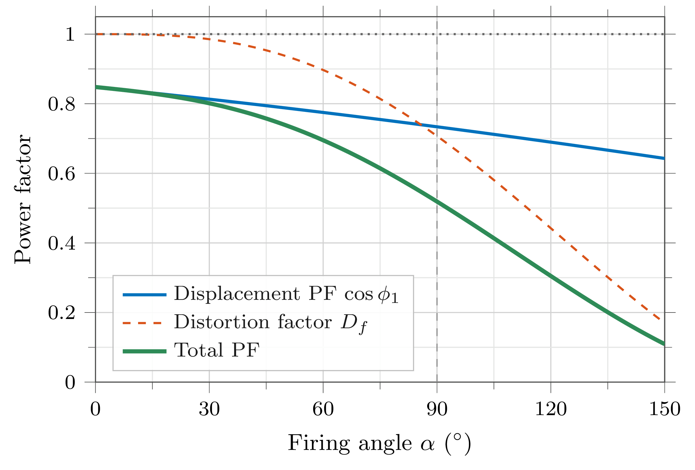
Input Power Factor of the Phase-Controlled Drive
- Stator current \(i_s(t)\) is non-sinusoidal.
- Displacement power factor \(\cos\phi_1\): phase lag of the fundamental current component relative to supply voltage.
- Distortion factor \(D_f\): accounts for harmonic content.
Consequence: As \(\alpha\) increases (speed reduced), both \(\cos\phi_1\) and \(D_f\) decrease simultaneously. A drive at 50% speed can draw a total power factor as low as 0.3–0.4.
Mitigation measures:
- Shunt power-factor correction capacitors at motor terminals.
- AC line reactors to reduce harmonic current injection to the supply.
- 12-pulse converter topology for large drives (Lecture 3).
Closed-Loop Cascade Controller
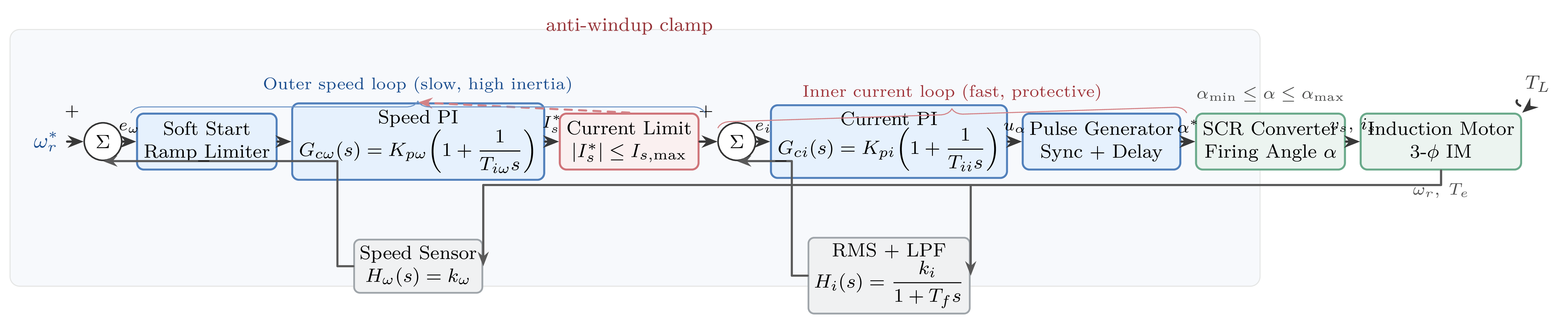
- Regulates stator rms current to reference \(I_s^*\).
- Protects SCR devices and motor windings from over-current.
- Bandwidth set several times larger than the outer speed loop.
- PI controller converts speed error to current demand \(I_s^*\).
- Soft-start ramp limits \(\omega_r^*\) to control acceleration current.
- Limiter prevents \(I_s^*\) from exceeding \(I_{s,\max}\).
- Enables stable operation in open-loop-unstable high-slip regions.
Controller Design Principles — Plant Model
The motor stator winding is modelled as a first-order electrical lag:
The PI current controller:
tuned so that the inner closed-loop bandwidth \(\omega_{c,I} \gg \omega_{c,\omega}\) (speed bandwidth).
Outer loop plant (speed): Once the inner loop is closed and fast, the mechanical sub-system is approximated as an integrator:
- Inner loop bandwidth \(\geq 5\times\) outer loop bandwidth to justify the cascade approximation.
- Inner integral time \(T_{ic} \approx T_I\) (pole-zero cancellation).
- Outer integral time set by required speed-error settling time.
- Anti-windup on both PI stages to handle saturation during run-up.
Exact pole-zero cancellation is not achievable in practice; however the cascade structure is robust to parameter variations because the inner loop largely masks motor impedance changes from the outer loop.
Efficiency of the Phase-Controlled Drive
Approximate upper bound (stator resistance and core losses neglected):
Complete efficiency expression:
Phase control vs. external resistance:
- Resistance control: slip power dissipated in external resistors; motor rotor losses are lower.
- Phase control: all slip power dissipated inside the rotor — motor runs hotter.
- Both share the same fundamental efficiency ceiling.
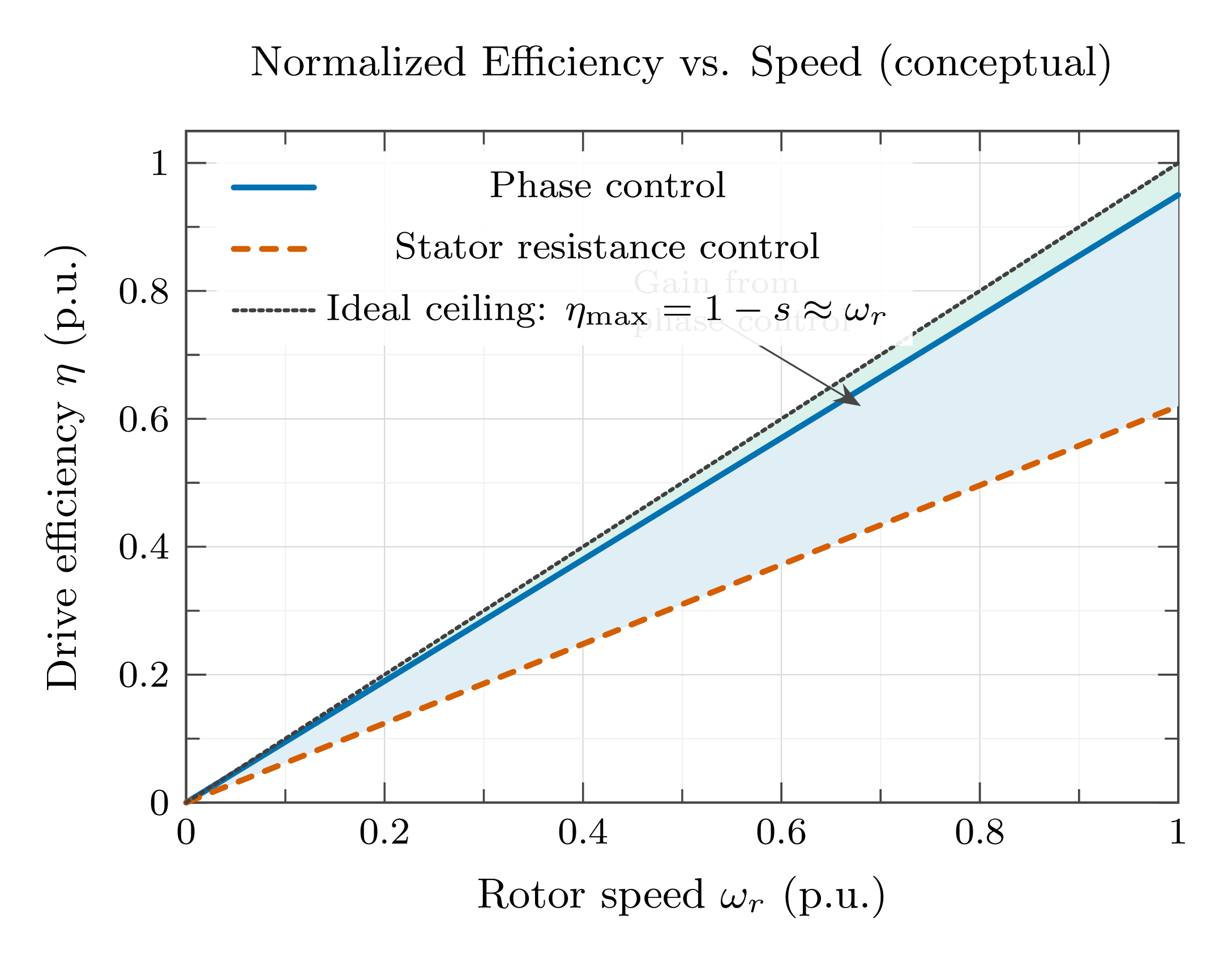
Fundamental limitation: Both methods share the ceiling \(\eta \leq (1-s)\). To surpass this, slip power must be returned to the supply — topic of Lecture 3.
Applications of Phase-Controlled IM Drives
- Centrifugal pumps and fans (30–100% speed range)
- Compressors and blowers
- Extruders and injection-moulding machines
- Mine hoists, ski-lifts, conveyors
- Wire-drawing and textile machinery
- Limit starting inrush to \({\leq}\,3{\times}I_{\text{rated}}\)
- Replaces star-delta starters: smoother torque, less mechanical shock
- Solid-state — no moving contacts
- Resistance heating furnaces
- Light dimmers and UV-curing lamps
- AC voltage regulators for sensitive loads
Despite being largely superseded by PWM-inverter drives for new installations, phase-controlled drives remain cost-effective for large-motor applications where the required speed range is limited (\({\leq}\,30\,\%\) of rated speed).
Why Recover Slip Energy? — Principle
In every slip-controlled induction-motor drive:
This fraction of air-gap power is dissipated as heat. Can it instead be returned to the supply?
SER principle: Insert a controllable back-EMF source \(E_r\) in the rotor circuit. It extracts \(s\,P_{ag}\) from the rotor; a power converter feeds this energy back to the AC supply. Speed is set by adjusting \(|E_r|\).
Machine requirement: The rotor circuit must be externally accessible \(\Rightarrow\) Wound-rotor IM with slip rings. Squirrel-cage machines cannot be used.
The converter is rated at only \(s_{\max}\times P_{\text{motor}}\) — a significant cost advantage for limited speed ranges.
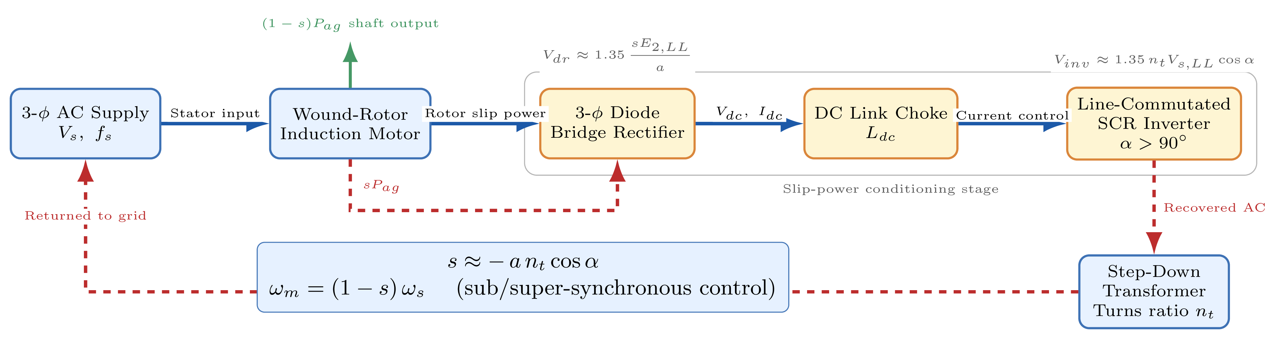
Slip-Energy Recovery — DC-Link Voltage Balance
- Diode bridge output: \(V_{dc} = 1.35\,s V_r\) (referred to rotor side)
- SCR line-inverter voltage (\(\alpha > 90°\), inverting): \(V_{inv} = -1.35\,n_t V_s\,|\cos\alpha|\)
Voltage balance in steady state (neglecting DC-link resistance drop):
Speed is set by the firing angle \(\alpha\) of the SCR inverter (\(\alpha > 90°\)).
The upper limit of \(\alpha\) is set by the commutation margin angle required to reliably turn off the SCR inverter thyristors.
For a 30% speed range, the converter is rated at only 30% of the motor nameplate power — far cheaper than a full-rated variable-frequency drive.
Sign convention note: For \(\alpha > 90°\) the SCR bridge operates in inverter mode (negative average voltage), which opposes the diode-bridge output and controls the DC-link current, hence the slip.
Summary and Preview
- \(T_L = B_L\omega_r^k\): rotor current peaks at intermediate slip, not at standstill.
- Thermal rating governed by rms stator current over the full speed range.
- Power factor degrades with \(\alpha\): both displacement PF and distortion factor fall; shunt capacitors or line reactors are needed.
- Cascade PI controller: inner current loop + outer speed loop + soft-start.
- \(\eta \approx (1-s)\): phase control more efficient than resistor control, but both are fundamentally bounded.
- SER principle: wound-rotor IM + diode bridge + DC choke + SCR inverter + transformer.
- Speed equation: \(s = (n_t V_s / V_r)|\cos\alpha|\).
- Per-phase equivalent circuit of the SER drive (stator-referred)
- Key result: \(T_e = K_t\,I_{dc}\) (DC-machine analogy)
- Torque–speed performance and efficiency
- Harmonic currents: sixth-harmonic pulsating torque
- Supply-side harmonic distortion and mitigation
- Starting procedure and converter ratings
- Closed-loop control of the SER drive