Lecture 6C — Scope and Objectives
- Phase (stator voltage) control: \(\eta \leq (1-s)\).
- Power factor degrades severely with increasing \(\alpha\).
- SER principle: diode bridge + DC choke + SCR inverter return \(sP_{ag}\) to supply.
- Speed equation: \(s = (n_t V_s/V_r)\,|\cos\alpha|\).
- SER requires a wound-rotor IM with accessible slip rings.
- Per-phase equivalent circuit (stator-referred)
- Torque expression and DC-machine analogy: \(T_e = K_t I_{dc}\)
- SER performance and efficiency
- Harmonic currents: sixth-harmonic pulsating torque; 5th and 7th orders
- Supply-side harmonic distortion and mitigation strategies
- Transformer turns-ratio design
- Starting procedure and converter ratings
- Closed-loop \(I_{dc}\) and speed control
Per-Phase Equivalent Circuit — Stator-Referred
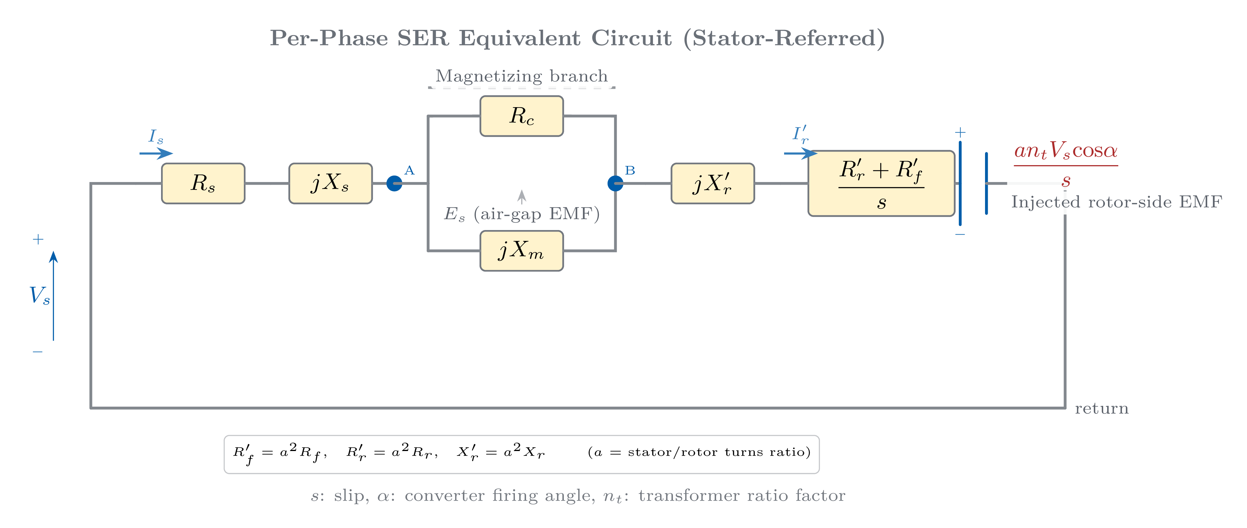
Rotor-loop KVL (referred to stator, per phase):
where \(E_s\) is the stator-referred air-gap EMF and the second term is the referred back-EMF of the SCR inverter.
Parameter referral (stator-to-rotor turns ratio \(a\)):
- \(R_f'\): referred DC-link resistance (choke + diode forward drop).
- The back-EMF term opposes the rotor current, controlling the DC-link current \(I_{dc}\) and hence slip.
Electromagnetic Torque — DC-Machine Analogy
Stator impedance neglected:
Neglecting rotor leakage \(X_r'\) (valid for small operating slips) and using the 6-pulse diode bridge relation \(I_r' = (\sqrt{6}/\pi)\,a\,I_{dc}\):
The stator supply voltage holds the air-gap flux approximately constant — analogous to the field flux in a DC machine.
Practical significance:
- Simple single-variable torque control.
- No coordinate transformation required.
- No three-phase current regulation needed.
- Controller design mirrors a standard phase-controlled DC drive.
- Only one current transducer (\(I_{dc}\)) needed in the inner loop.
SER Drive — Performance and Efficiency
Key performance results:
- High motor power factor maintained across the speed range (motor operates near rated flux at all speeds).
- Recovered slip power increases as speed decreases \(\Rightarrow\) efficiency greatly improved compared with phase control.
| Drive Scheme | Efficiency \(\eta\) |
|---|---|
| Slip-energy recovery | \(\approx 86\,\%\) |
| Phase control | \(\approx 60\,\%\) |
| External resistance | \(\approx 45\,\%\) |
Take-away: SER achieves \(\approx 86\,\%\) efficiency at \(60\,\%\) speed — more than 25 percentage points better than phase control alone.
Harmonic Currents and Sixth-Harmonic Pulsating Torque
Characteristic orders: \(n = 6k \pm 1\), \(k = 1,2,3,\ldots\) — Magnitudes: \(I_{r,n} = I_{r,1}/n\).
Mechanism of sixth-harmonic pulsating torque:
- The 5th harmonic rotates backward at \(5\omega_s\); its speed relative to the fundamental stator flux is \(6\omega_s\).
- The 7th harmonic rotates forward at \(7\omega_s\); its relative speed is also \(6\omega_s\).
- Both together produce a torque pulsation at \(6\omega_s\) (sixth harmonic of supply frequency).
Sixth-harmonic pulsating torque ratio:
- Large machines: \(X_\ell \leq 2\,\%\) p.u. \(\Rightarrow\) \(|T_{6h}| \leq 1.3\,\%\,T_e\)
- Small machines: \(X_\ell \leq 5\,\%\) p.u. \(\Rightarrow\) \(|T_{6h}| \leq 3.3\,\%\,T_e\)
Sixth-harmonic torque causes minor vibration and acoustic noise. For fan and pump loads this is negligible in practice.
DC-link choke \(L_{dc}\): Sized to suppress sixth-harmonic ripple in the DC-link current, keeping \(I_{dc}\) smooth and torque ripple small.
Individual Harmonic Torques — 5th and 7th Orders
Fifth-harmonic slip and torque ratio:
The 5th harmonic current rotates backward; its effective slip referred to synchronous speed is:
The 5th harmonic produces a braking average torque; its ratio is:
Seventh-harmonic: The 7th harmonic rotates forward; its effective slip is \(s_7 = (s-6)/7 \approx -6/7\). It produces a small forward average torque, even smaller in magnitude than the 5th.
Key conclusion: Both 5th and 7th individual harmonic average torques remain below 1% of rated torque at all operating slips. Entirely negligible for fan, pump, and compressor loads.
- 6th-harmonic pulsating torque: \(\leq 3.3\,\%\) for typical machines.
- Individual 5th/7th average torques: \(< 1\,\%\) of \(T_e\).
- Dominant practical concerns: additional motor copper and iron losses from harmonic currents; DC-link current ripple (mitigated by \(L_{dc}\)); supply-side line current harmonics.
Supply-Side Harmonic Distortion and Mitigation
Both the diode bridge and the SCR inverter are 6-pulse converters drawing non-sinusoidal currents from the AC supply. The characteristic harmonic orders are:
with magnitudes \(I_n \approx I_1 / n\) for an ideal quasi-square waveform.
Effects on the supply system:
- Voltage distortion at the point of common coupling (PCC).
- Interference with other sensitive loads sharing the same bus.
- Additional losses in supply transformers and cables.
- THD may violate grid codes (e.g. IEEE 519, IEC 61000-3-2).
AC-line reactor (3–5% impedance): reduces harmonic current amplitude and protects SCRs from supply voltage spikes.
12-pulse configuration: Two 6-pulse bridges fed from a dual-secondary transformer with 30° phase shift. Cancels 5th and 7th harmonics; only \(11,\,13,\,\ldots\) remain.
Tuned passive filter: LC branch tuned to the dominant harmonic (usually 5th); also provides reactive power compensation simultaneously.
Current THD at PCC reduces from \(\approx 29\,\%\) (6-pulse) to \(\approx 10\,\%\) (12-pulse) with no active electronics.
Transformer Turns-Ratio Design Principle
The speed equation \(s = (n_t V_s/V_r)\,|\cos\alpha|\) must be satisfied across the entire speed range with \(\alpha\) constrained to:
Selecting \(n_t\):
At minimum speed (\(s = s_{\max}\), \(\alpha = \alpha_{\max}\)):
- Larger \(n_t\) widens speed range but increases converter VA rating.
- Smaller \(n_t\) reduces converter cost but narrows the controllable speed band.
Design principle: \(n_t\) is chosen as the smallest value that achieves the required \(s_{\max}\) while keeping \(\alpha \leq \alpha_{\max}\). This simultaneously minimises transformer apparent power rating, SCR inverter voltage rating, and no-load reactive current.
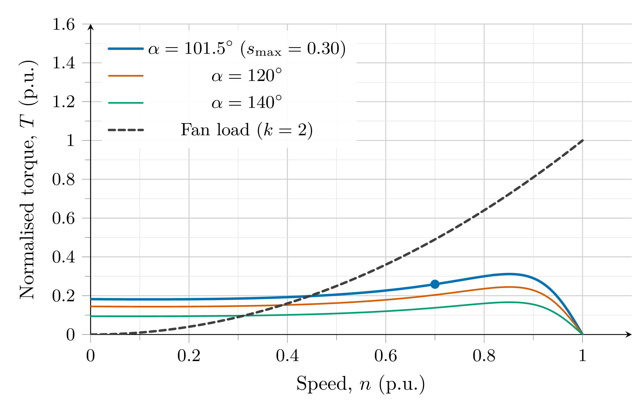
Practical speed-range rule:
A 70–100% speed range gives \(s_{\max} = 0.30\), so the converter is rated at 30% of motor power.
Starting Procedure and Converter Ratings
At standstill (\(s = 1\)): all air-gap power flows through the rotor as slip power. If the SER converter must handle this, its rating equals the full motor rating — defeating the economic advantage of the scheme.
Solution: Auxiliary rotor-resistance starting
- Insert external resistors in the rotor circuit at standstill; gate pulses to the SER converter are blocked.
- Motor accelerates on its wound-rotor characteristic with resistance control.
- When speed reaches \(\omega_{\min}\) (lower edge of the SER speed range), rotor resistors are switched out.
- SER converter takes over and regulates speed within its designed range.
Thermal note: Starting resistors absorb the full rotor energy during acceleration. Liquid cooling is mandatory for large machines (MW class).
Economic benefit: For \(s_{\max} = 0.30\), converters rated at only 30% of motor power. Significant cost reduction vs. a full-rated variable-frequency drive. Primary economic justification for SER drives in large pump systems.
Closed-Loop Control — SER Drive
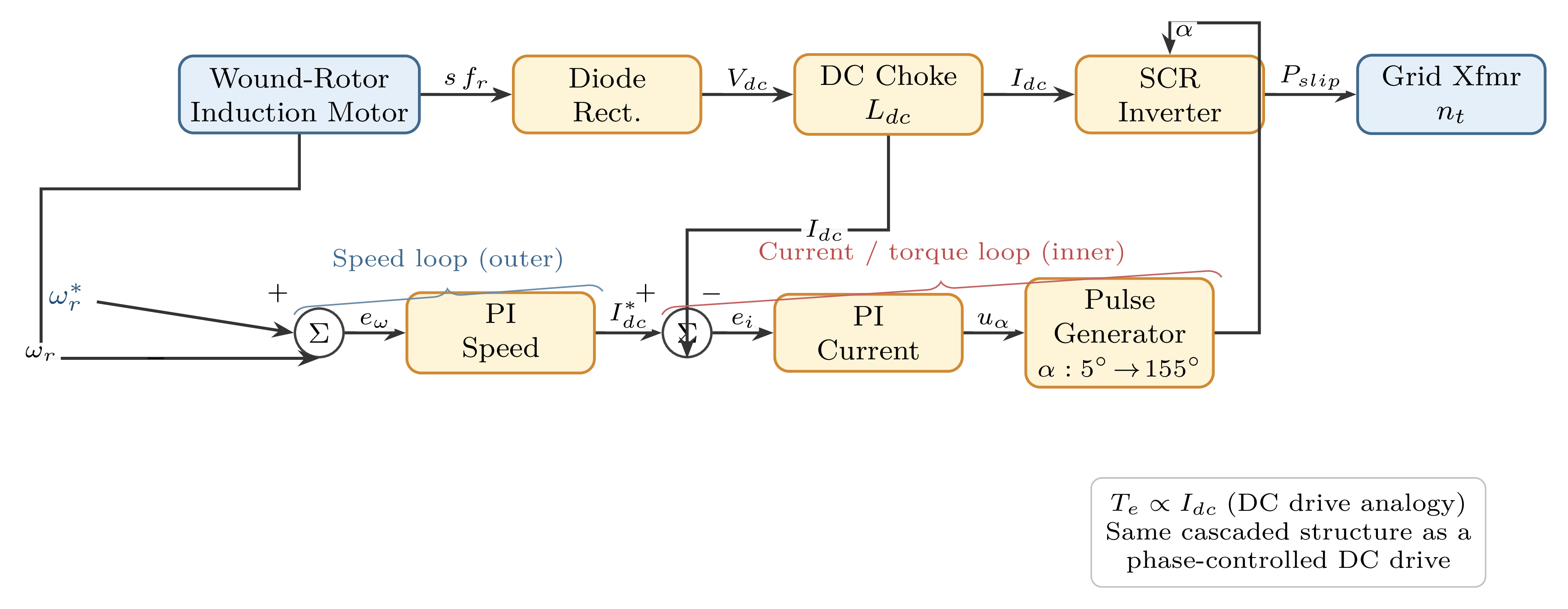
- Since \(T_e \propto I_{dc}\), current control is equivalent to torque control.
- PI controller output is the SCR firing angle \(\alpha\).
- Firing angle clamped at \(\alpha \leq \alpha_{\max} \approx 155°\) to preserve the commutation margin.
- Fast response; time constant \(\tau \approx L_{dc}/R_{dc}\).
- PI controller generates \(I_{dc}^*\) (current/torque demand).
- Structure mirrors a phase-controlled DC drive — same design methodology applies directly.
- One-quadrant operation only (subsynchronous motoring); PI output floored at zero.
- Soft-start limiter on \(\omega_r^*\) prevents over-current during run-up.
Summary and Preview
- Stator-referred equivalent circuit with referred back-EMF of the SCR inverter.
- \(T_e = K_t I_{dc}\): SER torque is structurally identical to a DC machine.
- SER efficiency \(\approx 86\,\%\) at \(60\,\%\) speed vs. \(\approx 60\,\%\) for phase control.
- 6th-harmonic pulsating torque: \(\leq 3.3\,\%\,T_e\) for typical machines.
- 5th/7th individual average harmonic torques: \(< 1\,\%\) of \(T_e\).
- Supply-side harmonics (\(n = 6k\pm1\)): mitigated by line reactors, 12-pulse topology, or tuned passive filters.
- Turns ratio \(n_t\) chosen to cover the required \(s_{\max}\) at minimum converter rating.
- Auxiliary resistor starting required; liquid cooling for MW-class machines.
- Cascade \(I_{dc}\)–\(\omega_r\) controller mirrors DC drive design.
- Historical context: Kramer and Scherbius drives
- Static Scherbius drive: bidirectional converter for four-quadrant operation
- Supersynchronous operation: power flow and speed range
- Industrial application: large pump drives and affinity laws
- Wind energy: DFIG concept, MPPT and reactive power control
- Unified comparison: all three drive types side by side