Key Results from Lectures 5A and 5B
- Slip: \(s = \dfrac{n_s - n_r}{n_s}\)
- Per-phase equivalent circuit with \(R_r'/s\) rotor branch
- Power ratio: \(P_{ag} : P_{r,Cu} : P_{conv} = 1 : s : (1-s)\)
- Torque: \(T_{em} = \dfrac{P_{ag}}{\omega_s} = \dfrac{3\,I_r'^{\,2}\,R_r'}{s\,\omega_s}\)
- Power factor always lagging; poor at light loads
How does \(I_r'\) vary with slip? What shape does \(T_{em}(s)\) take? Where is the maximum torque? How do we measure the circuit parameters? — All answered in this lecture.
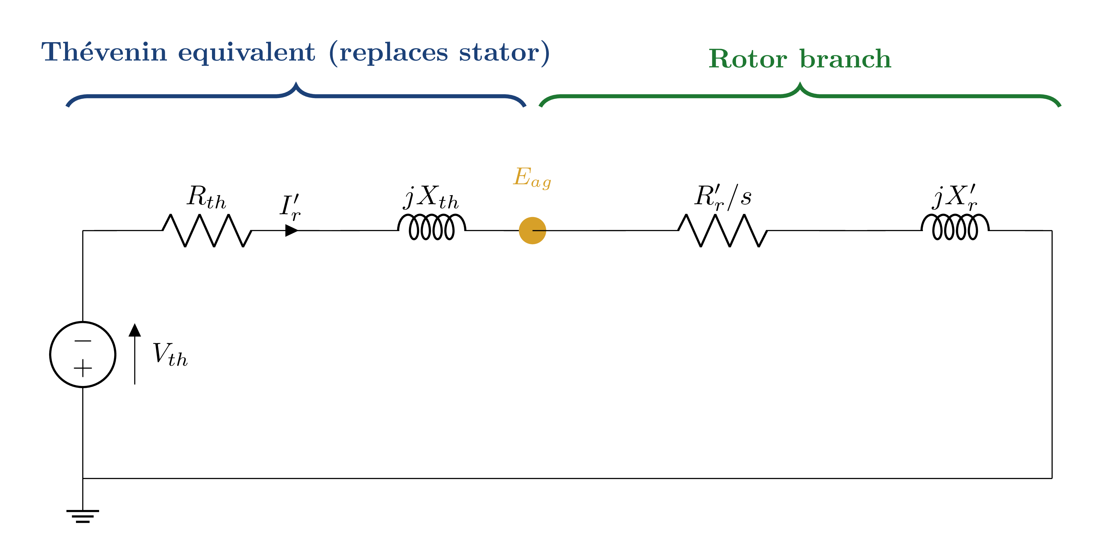
Thévenin Equivalent — Why and How
To find \(I_r'\) as a function of slip, we replace everything to the left of the air-gap nodes with its Thévenin equivalent — a simple series circuit remains, making torque vs. slip analysis tractable.
Typical: \(R_{th} \approx R_s\), \(\quad X_{th} \approx X_s\)
Rotor Current & Fundamental Torque-Slip Equation
At small \(s\): \(R_r'/s \gg (R_{th},\; X_{th}+X_r')\), so the denominator \(\approx (R_r'/s)^2\):
Torque is directly proportional to slip in the normal operating region — the motor is self-regulating.
| Slip | \(R_r'/s\) | Effect on \(T_{em}\) |
|---|---|---|
| \(s = 1\) | \(= R_r'\) (small) | Standstill torque |
| \(0 < s < s_{max}\) | Moderate | Torque rising |
| \(s = s_{max}\) | Optimal | Peak (breakdown) torque |
| \(s \to 0\) | \(\to \infty\) | \(T \to 0\) |
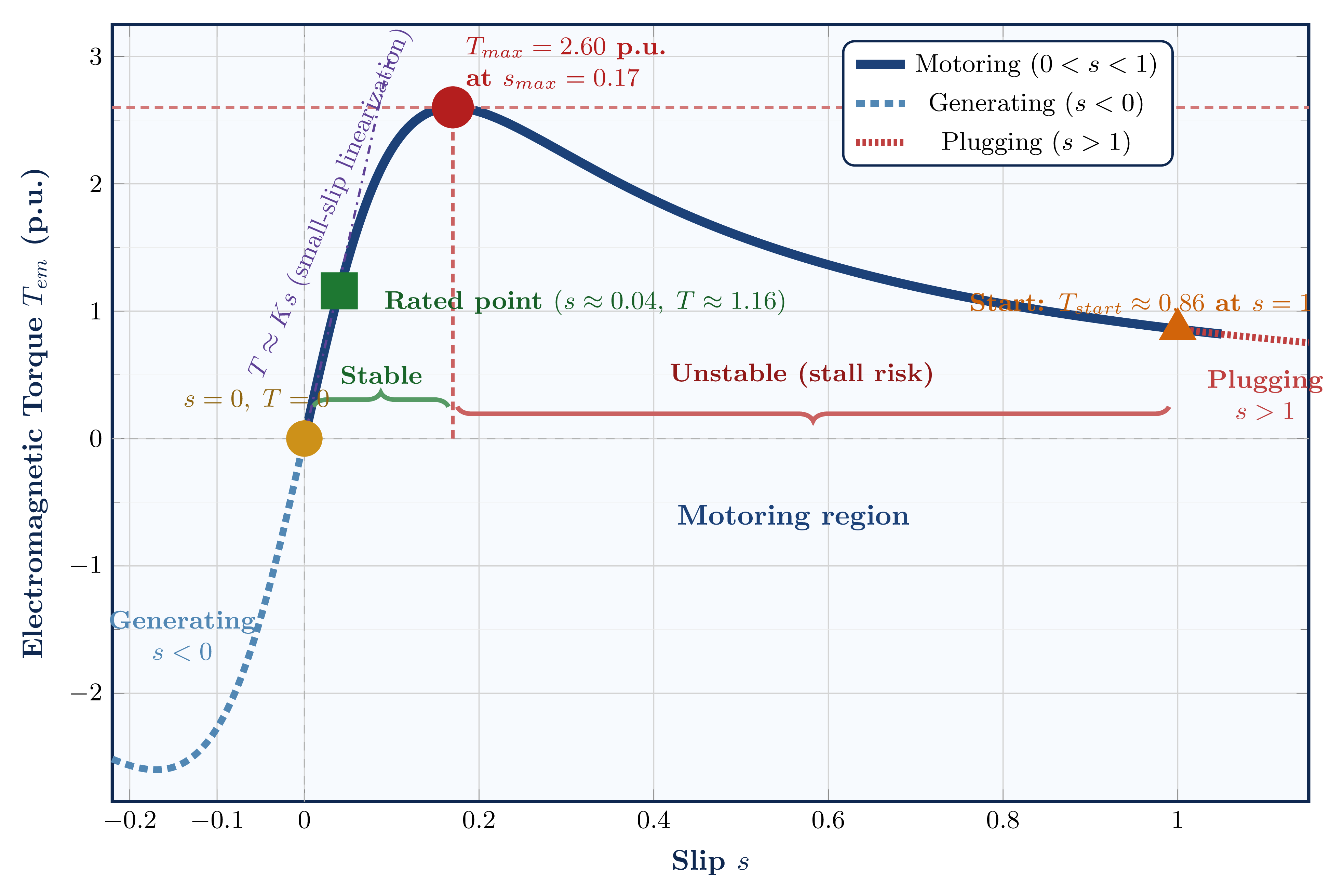
The Complete Torque-Slip Curve
| Point | Slip | Significance |
|---|---|---|
| Synchronous | \(s = 0,\; T = 0\) | No electromagnetic induction; theoretical only |
| Rated operating | \(s \approx 0.04\) | Normal stable operating point; self-regulating |
| Breakdown | \(s = s_{max}\) | Maximum / pull-out torque; stability boundary |
| Starting | \(s = 1\) | Locked-rotor; high current, moderate torque |
| Generating | \(s < 0\) | External prime mover drives rotor above \(n_s\) |
Stable vs. Unstable Operating Regions
Self-regulating mechanism:
- Load torque \(T_L\) increases
- Motor decelerates ⇒ slip \(s\) increases
- In linear region: \(T_{em} = Ks\) ⇒ \(T_{em}\) increases
- New equilibrium: \(T_{em} = T_L\) at slightly higher slip
- Speed barely changes — stiff speed characteristic
Positive feedback — runaway to stall:
- Load torque \(T_L > T_{em}\) momentarily
- Motor decelerates ⇒ slip increases
- Now past \(s_{max}\): \(T_{em}\) decreases with increasing \(s\)
- Gap between \(T_L\) and \(T_{em}\) grows
- Motor stalls (comes to rest)
Motor must never be operated continuously in this region.
Ensures the motor survives transient overloads without stalling. This generous margin is deliberately designed in by the manufacturer.
Maximum Torque — Derivation & Significance
Setting \(dT_{em}/ds = 0\) and solving (treating \(V_{th}\), \(R_{th}\), \(X_{th}\), \(R_r'\), \(X_r'\) as constants):
Simplified (\(R_{th} \ll X_{th}+X_r'\)):
\[s_{max} \approx \frac{R_r'}{X_{th}+X_r'}\]These two facts explain the entire family of torque-slip curves and the wound-rotor motor starting strategy. Changing rotor resistance shifts the peak left or right on the slip axis, but never changes the height of the peak.
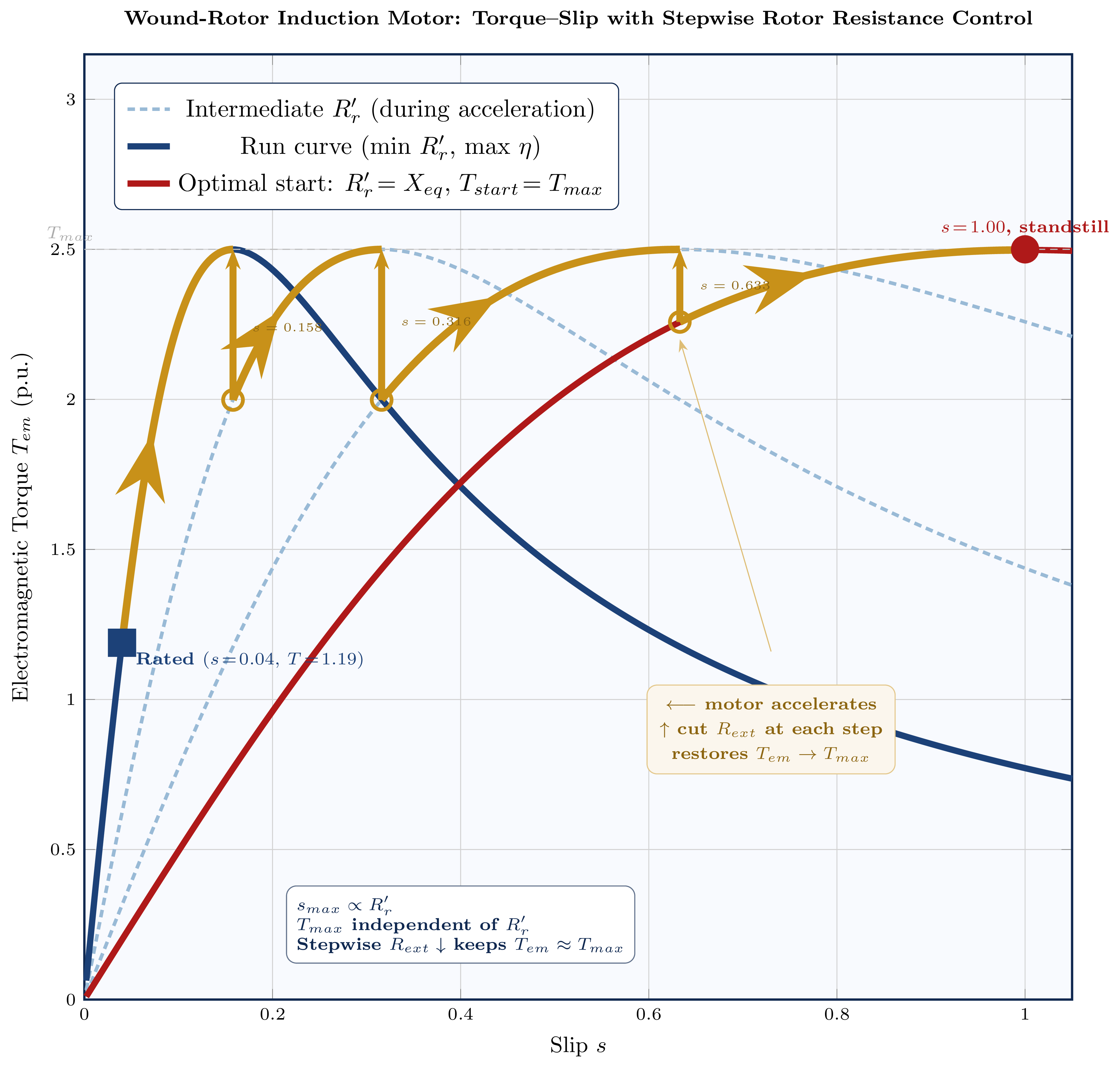
Wound-Rotor Starting Strategy & Family of Curves
- Start with high external \(R_{ext}\) so that \(s_{max} = 1\) ⇒ \(T_{start} = T_{max}\)
- As motor accelerates, cut resistance in steps — each step restores \(T_{em} \approx T_{max}\)
- Rated speed: all resistance removed; low-\(R_r'\) run curve gives high efficiency
- All curves share the same \(T_{max}\)
- Higher \(R_r'\) shifts peak to larger slip
- Low \(R_r'\): peak near synchronous speed; high efficiency, low \(T_{start}\)
- Optimal \(R_r'\): \(s_{max} = 1\) ⇒ \(T_{start} = T_{max}\)
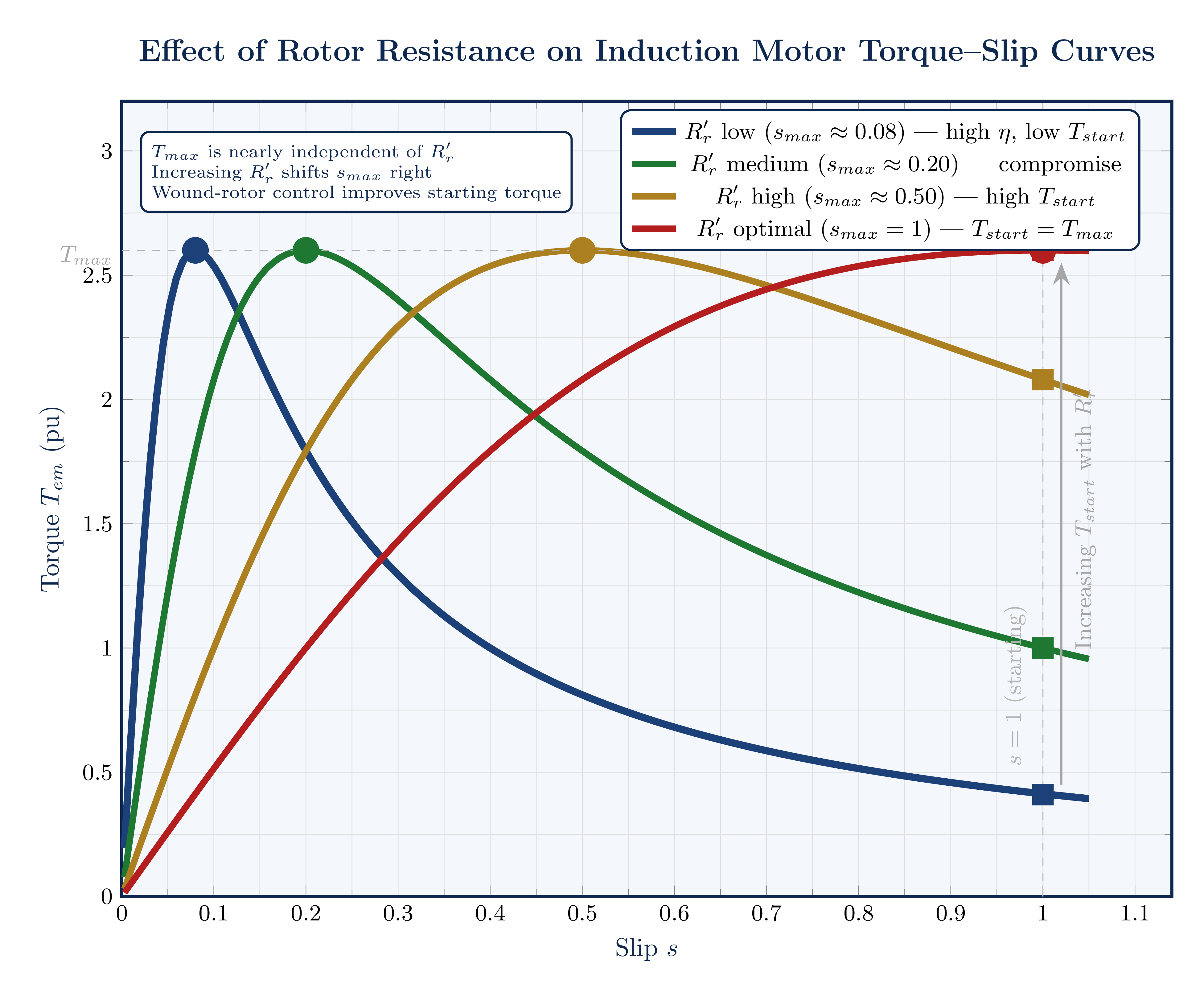
Fig. 3 — Increasing \(R_r'\) shifts \(s_{max}\) toward standstill while \(T_{max}\) remains constant.
Starting Torque & Current
At \(s = 1\), the rotor branch impedance is at its minimum. Typically:
High inrush current with only moderate torque — the fundamental starting problem addressed in Lecture 5D.
| Motor Type | \(T_{max}/T_{rated}\) |
|---|---|
| General purpose | 2.0–2.5 |
| High-torque | 2.5–3.0 |
| Wound rotor | 2.5–3.5 |
NEMA Design Classifications
A single squirrel-cage motor cannot simultaneously achieve low starting current (needs low \(R_r'\)), high starting torque (needs high \(R_r'\)), and high rated efficiency (needs low \(R_r'\)). NEMA classifications codify standard compromises for different industrial applications.
| Class | \(T_{st}/T_r\) | Rated Slip | Best For |
|---|---|---|---|
| A | 1.0–1.5 | <5% | Fans, pumps — low starting torque loads |
| B (Industry Standard) | ≥1.5 | <5% | Compressors, conveyors — general purpose |
| C | 2.0–2.5 | <5% | Crushers, reciprocating compressors |
| D | >2.5 | 7–11% | Presses, cranes — high starting torque |
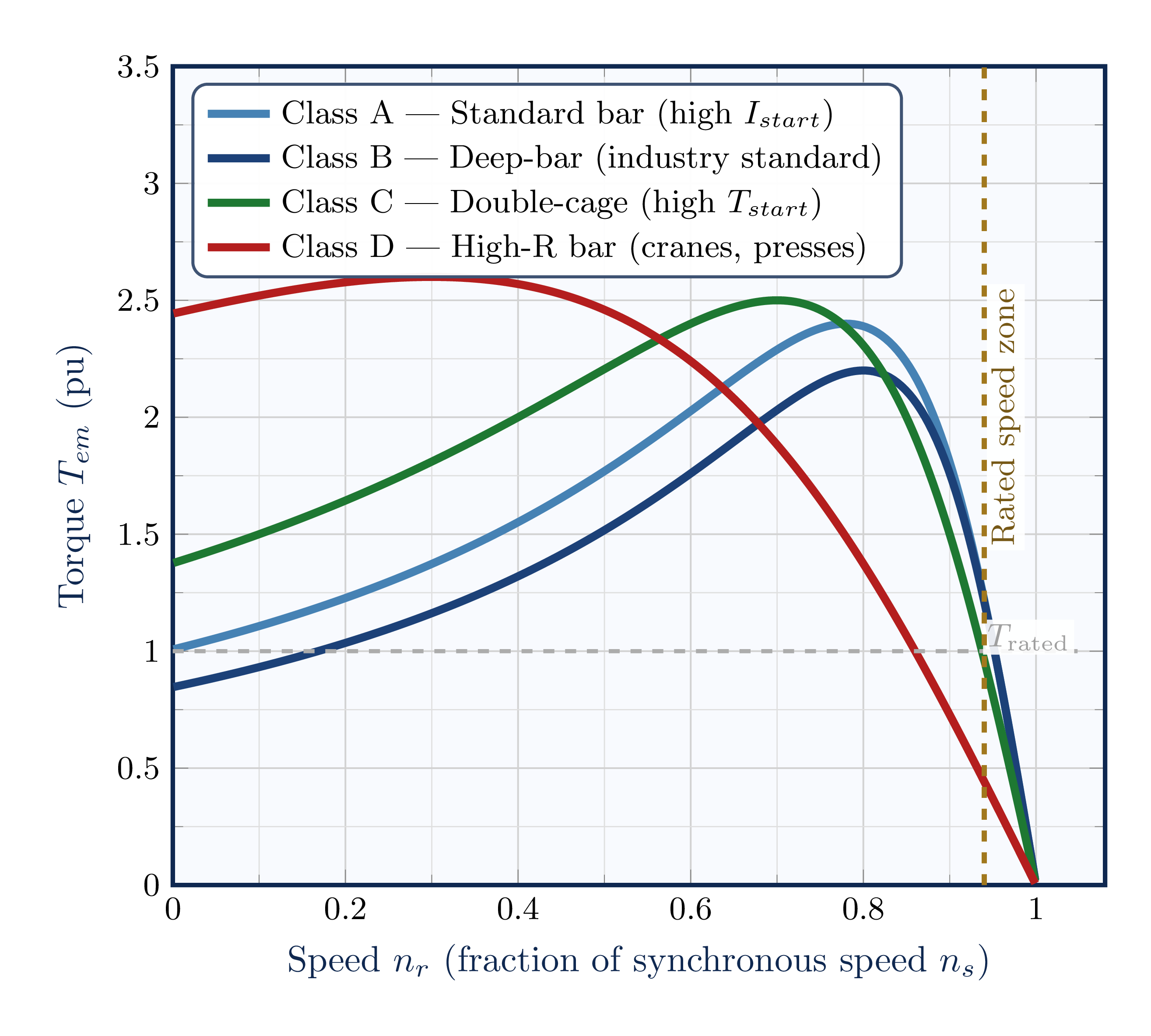
Deep-bar or double-cage rotor achieves both limited starting current and adequate starting torque. Over 90% of new industrial motor installations use Class B.
Inherently high \(R_r'\) gives maximum starting torque, but rated slip of 7–11% means significant rotor copper loss at full load — efficiency is poor.
Measurement of Motor Parameters — Overview
Before using the equivalent circuit for calculation, we need numerical values for all six parameters. Manufacturers seldom provide all of them — they must be extracted experimentally using three standard tests.
| Test | Operating Condition | Parameters Extracted |
|---|---|---|
| DC Resistance | Standstill, DC supply | \(R_s\) |
| No-Load | Rated \(V\) & \(f\); free shaft (\(s \approx 0\)) | \(R_c\), \(X_m\) |
| Locked-Rotor | Low \(V\), rated \(I\); \(s = 1\) | \(R_r'\), \(X_s\), \(X_r'\) |
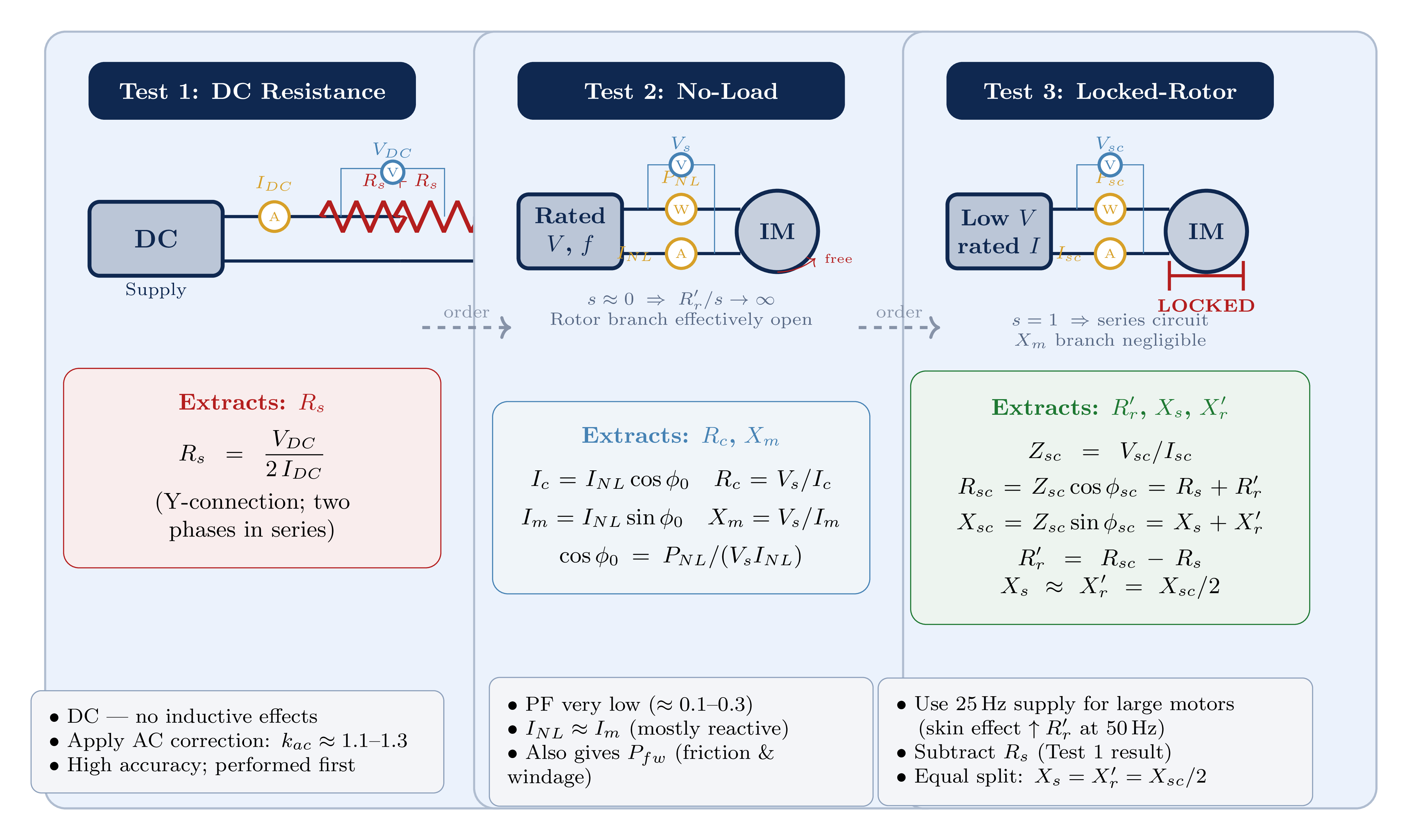
Test 1 — DC Resistance Test (Extracts \(R_s\))
- Apply DC voltage \(V_{DC}\) between two stator line terminals with rotor at standstill
- Measure DC current \(I_{DC}\)
- Two stator phase windings in series (for Y-connection)
DC eliminates inductance — only resistance appears in the measurement. Any AC voltage would cause an additional voltage drop across \(X_s\), giving an incorrect (higher) resistance reading.
- Small motors (<5 kW): \(R_s \approx 1\text{–}10\ \Omega\)
- Large motors (>100 kW): \(R_s \approx 0.01\text{–}0.1\ \Omega\)
- AC skin effect correction factor: \(k_{ac} \approx 1.1\text{–}1.3\)
Test 2 — No-Load Test (Extracts \(R_c\) and \(X_m\))
Apply rated three-phase voltage at rated frequency with shaft uncoupled (no mechanical load). Motor runs near synchronous speed (\(s \approx 0\)), so \(R_r'/s \to \infty\) and the rotor branch carries negligible current. The magnetising branch dominates.
Measure: \(V_s\) (phase), \(I_{NL}\), \(P_{NL}\) (per phase)
\[\cos\phi_0 = \frac{P_{NL}}{V_s\,I_{NL}}\] \[I_c = I_{NL}\cos\phi_0 \;\Rightarrow\; R_c = \frac{V_s}{I_c}\] \[I_m = I_{NL}\sin\phi_0 \;\Rightarrow\; X_m = \frac{V_s}{I_m}\]- No-load current \(I_{NL}\) is mostly reactive (\(I_m \gg I_c\)) — the no-load power factor is very low (\(\approx 0.1\text{–}0.3\))
- The wattmeter reading \(P_{NL}\) captures both core losses (\(P_{core} = V_s^2/R_c\)) and friction & windage losses
- At \(s \approx 0\): the rotor branch is effectively open circuit; all current flows through \(R_c \parallel jX_m\)
Test 3 — Locked-Rotor Test (Extracts \(R_r'\), \(X_s\), \(X_r'\))
Rotor is mechanically locked (\(s = 1\)). Apply reduced three-phase voltage until rated current flows. At \(s = 1\), \(R_r'/s = R_r'\) (minimum rotor impedance), and \(X_m\) carries negligible current. The circuit reduces to a series combination: \((R_s+R_r') + j(X_s+X_r')\).
Measure: \(V_{sc}\), \(I_{sc}\), \(P_{sc}\) (per phase)
\[Z_{sc} = \frac{V_{sc}}{I_{sc}}, \qquad \cos\phi_{sc} = \frac{P_{sc}}{V_{sc}\,I_{sc}}\] \[R_{sc} = Z_{sc}\cos\phi_{sc} = R_s + R_r'\] \[X_{sc} = Z_{sc}\sin\phi_{sc} = X_s + X_r'\] \[R_r' = R_{sc} - R_s\] \[X_s \approx X_r' = \frac{X_{sc}}{2} \qquad \text{(NEMA A, B, D)}\]| NEMA Class | \(X_s/X_{sc}\) | \(X_r'/X_{sc}\) |
|---|---|---|
| A, B, D | 0.50 | 0.50 |
| C | 0.30 | 0.70 |
- For large motors, use a 25 Hz supply — at 50 Hz, skin effect inflates \(R_r'\) above its true value at rated frequency
- Apply reduced voltage to avoid thermal damage from the locked-rotor current
- The equal-split \(X_s = X_r'\) is an approximation valid for NEMA A, B, and D motors
Lecture Summary
| Test | Condition | Measurements | Extracted | Formula |
|---|---|---|---|---|
| DC Resistance | Standstill, DC | \(V_{DC},\; I_{DC}\) | \(R_s\) | \(R_s = V_{DC}/(2I_{DC})\) |
| No-Load | Rated \(V\), \(f\); free shaft | \(V_s,\; I_{NL},\; P_{NL}\) | \(R_c\), \(X_m\) | \(R_c=V_s/I_c\), \(X_m=V_s/I_m\) |
| Locked-Rotor | Low \(V\), rated \(I\); \(s=1\) | \(V_{sc},\; I_{sc},\; P_{sc}\) | \(R_r'\), \(X_s\), \(X_r'\) | \(R_r'=R_{sc}-R_s\) |
Simplifies full circuit to a series loop; gives tractable \(I_r'(s)\) expression for all operating conditions.
\(T_{em} \approx Ks\) — linear, self-regulating. Motor is a "constant speed" machine in this region.
- \(s_{max} \propto R_r'\) (shifts the peak)
- \(T_{max}\) independent of \(R_r'\) (height unchanged)
Different torque-speed shapes via rotor bar geometry (skin effect); Class B is the industry standard (>90% of installations).
- DC resistance test first → \(R_s\)
- No-load test → \(R_c\), \(X_m\)
- Locked-rotor test last → \(R_r'\), \(X_s\), \(X_r'\)
Starting methods (DOL, Y-Δ, autotransformer, soft starters, VFD) and speed control methods (pole changing, voltage control, rotor resistance, V/f control with affinity laws).