Industrial Significance of Induction Machines
Ranging from fractional HP to several MW, they are inherently self-starting, robust, and virtually maintenance-free — making them the backbone of modern industrial systems.
- Pumps, fans, compressors, HVAC
- Conveyors, machine tools, hoists
- Electric vehicles & traction systems
- Industrial automation
- Energy savings: fan/pump power ∝ speed³
- Process control: precise speed & torque
- VFDs have made the induction motor the backbone of modern variable-speed drives
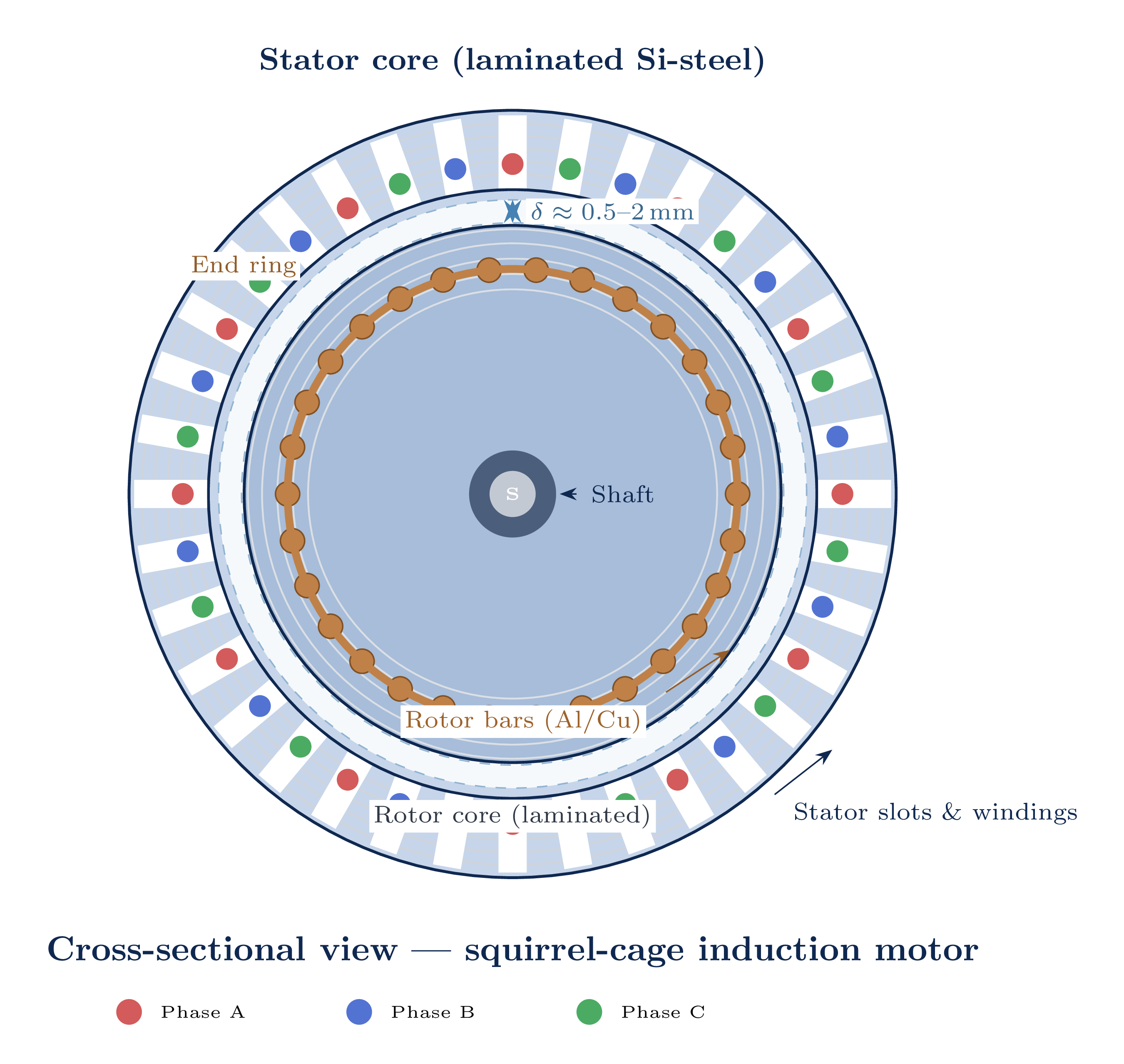
Physical Construction
- Laminated silicon-steel core — reduces eddy-current losses
- Slots accommodate 3-phase windings displaced 120° in space
- Housed in a non-magnetic steel frame
- Laminated steel core mounted on shaft
- Two types: squirrel cage or wound rotor
- Separated from stator by the critical air gap
- Uniform gap: 0.5–2 mm
- Critical for flux coupling
- Must remain perfectly uniform around the circumference
Squirrel Cage Rotor
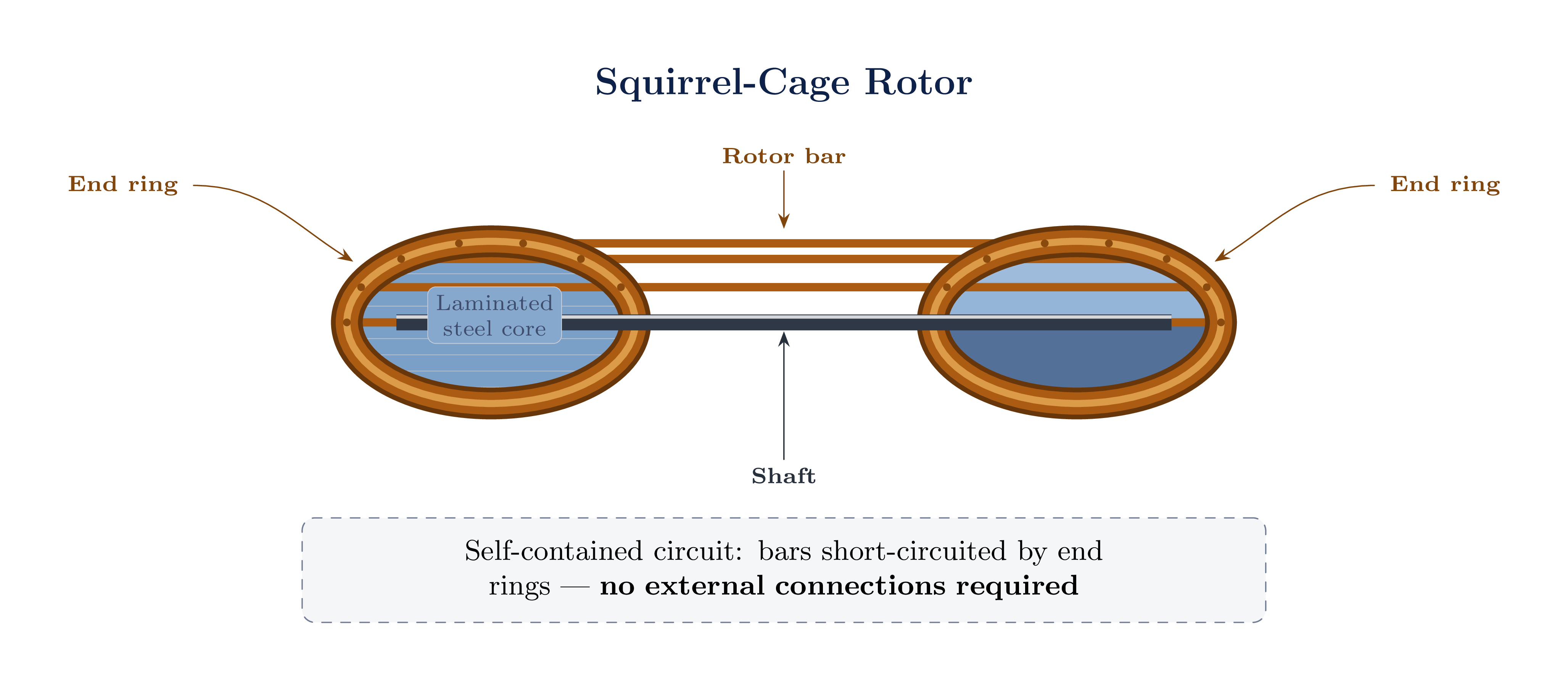
- Al/Cu bars cast into rotor slots
- Both ends short-circuited by end rings
- Completely self-contained — no external connections
- Simple, rugged, maintenance-free
- Lower cost; high reliability
- Fixed effective rotor resistance
- Small/medium motors: die-cast aluminium
- Large/high-efficiency: copper bars and rings
Over 90% of variable-speed applications use squirrel-cage motors with a Variable Frequency Drive (VFD), owing to their robustness and zero maintenance requirements.
Wound Rotor — Variable External Resistance
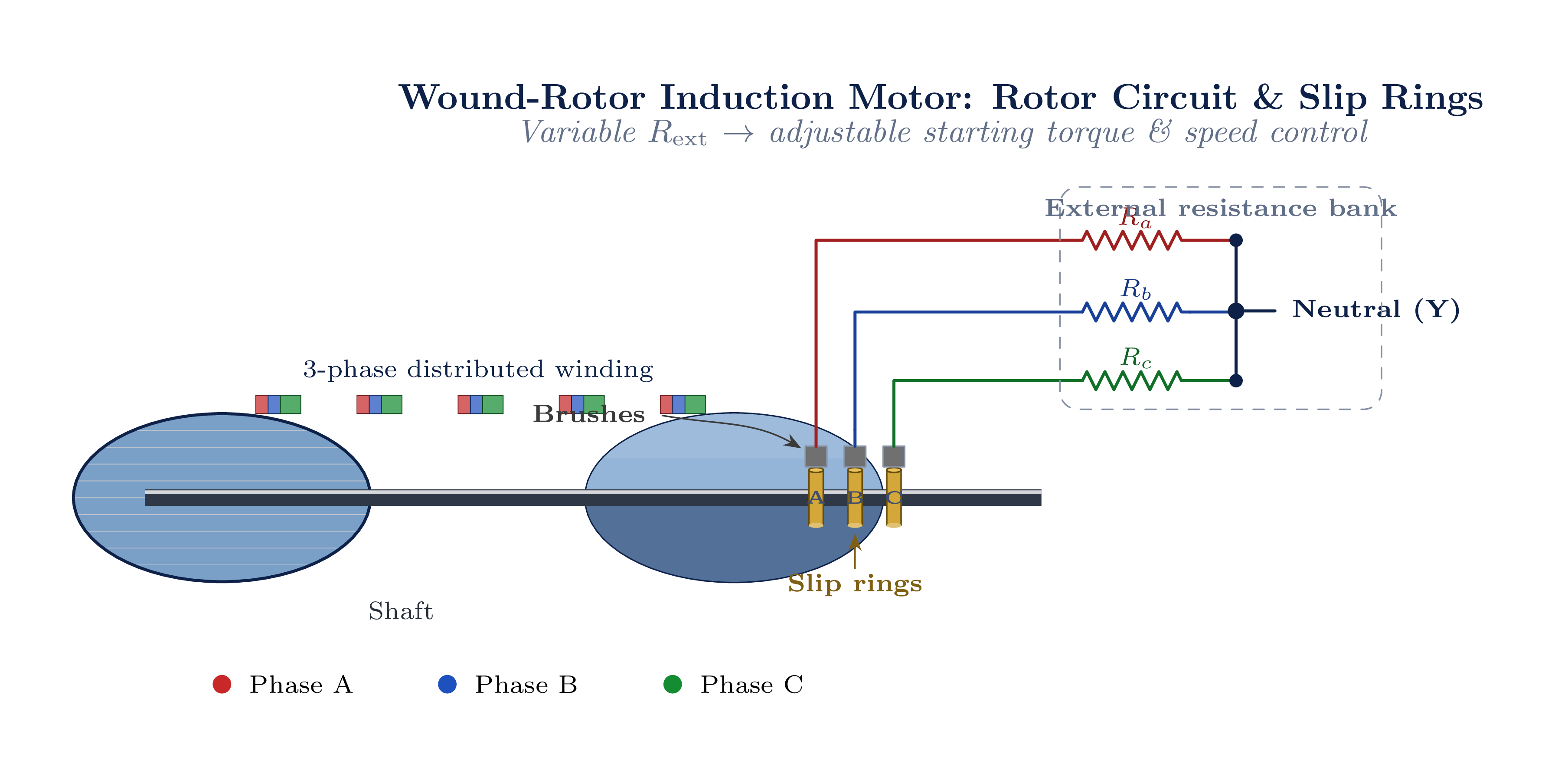
- Full 3-phase distributed winding on rotor
- Terminals brought out via slip rings & brushes
- External resistors connected to slip rings
- Cranes, crushers, mills
- Loads requiring high starting torque or controlled acceleration
- Variable effective rotor resistance
- Higher cost; brush maintenance required
Stator Winding Methods
- Stranded enamelled round wires placed randomly in slots
- Economical; suited for mass production
- Standard for fractional and integral HP motors
- Pre-formed rectangular conductors
- Better slot fill; more uniform insulation stress
- Used in large, medium-voltage machines
- Distributed: conductors spread over multiple slots — reduces MMF harmonics; standard in IMs
- Concentrated: all turns in one slot per pole — simpler; used in PMSM
| Class | Max Temperature Rise (K) | Limit (°C) |
|---|---|---|
| F | 105 | 155 |
| H | 125 | 180 |
VFD-Duty Insulation: PWM drives produce fast voltage pulses (high dV/dt) that stress turn-to-turn insulation. Use inverter-duty motors (NEMA MG1 Part 31) with any VFD application.
Enclosures & Bearings
- ODP — Open Drip-Proof: ventilated; indoors, clean environments
- TEFC — Totally Enclosed Fan-Cooled: most common industrial type
- TENV — Totally Enclosed Non-Ventilated: small motors (<5 kW)
- EXd — Explosion-proof: hazardous locations
Anti-friction (rolling element) — most common
- Ball or roller; grease-lubricated
- Handles radial & axial loads; sealed-for-life
Sleeve (plain) — large machines (>500 kW)
- Hydrodynamic oil film; quieter operation
- Regular oil-level monitoring required
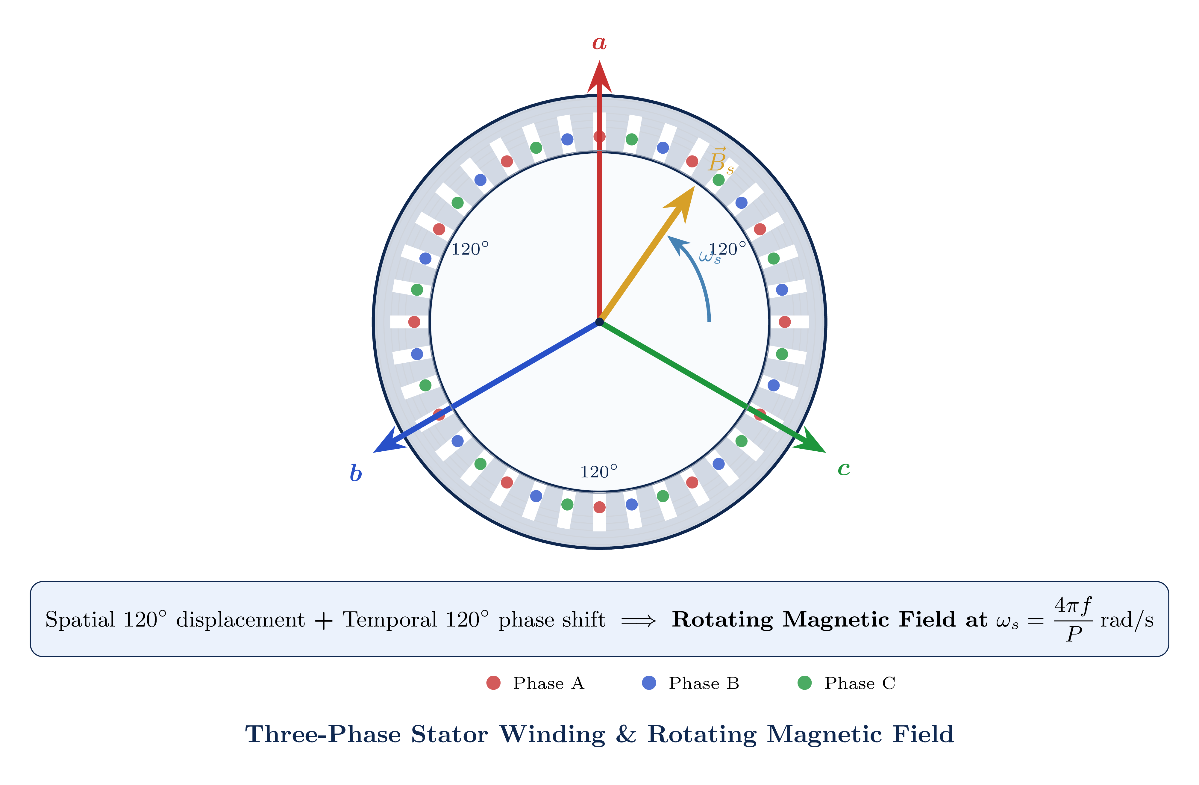
Rotating Magnetic Field
Three identical phase windings a, b, c are displaced 120° in space around the stator bore and supplied by balanced three-phase voltages:
vb(t) = Vm cos(ωet − 2π/3)
vc(t) = Vm cos(ωet + 2π/3)
The combination of space and time displacements produces a magnetic field that rotates at a constant angular velocity, sweeping past the rotor conductors and inducing EMF.
- Suppose ωr = ωs (hypothetically)
- No relative motion between field and rotor
- ⇒ No change of flux linkage in rotor conductors
- ⇒ No induced EMF (Faraday's law)
- ⇒ No rotor current
- ⇒ No electromagnetic torque
- ⇒ Load decelerates rotor below ωs
Synchronous Speed of the Rotating Field
ωs = 4πf / P [rad/s]
| Number of Poles P | Synchronous Speed ns (rpm) |
|---|---|
| 2 | 3000 |
| 4 | 1500 |
| 6 | 1000 |
| 8 | 750 |
Slip — The Fundamental Parameter
fr = s · f
| Motor Size | Slip s | Percentage |
|---|---|---|
| Small (<5 kW) | 0.04 – 0.08 | 4 – 8% |
| Medium (5–100 kW) | 0.02 – 0.04 | 2 – 4% |
| Large (>100 kW) | 0.005 – 0.02 | 0.5 – 2% |
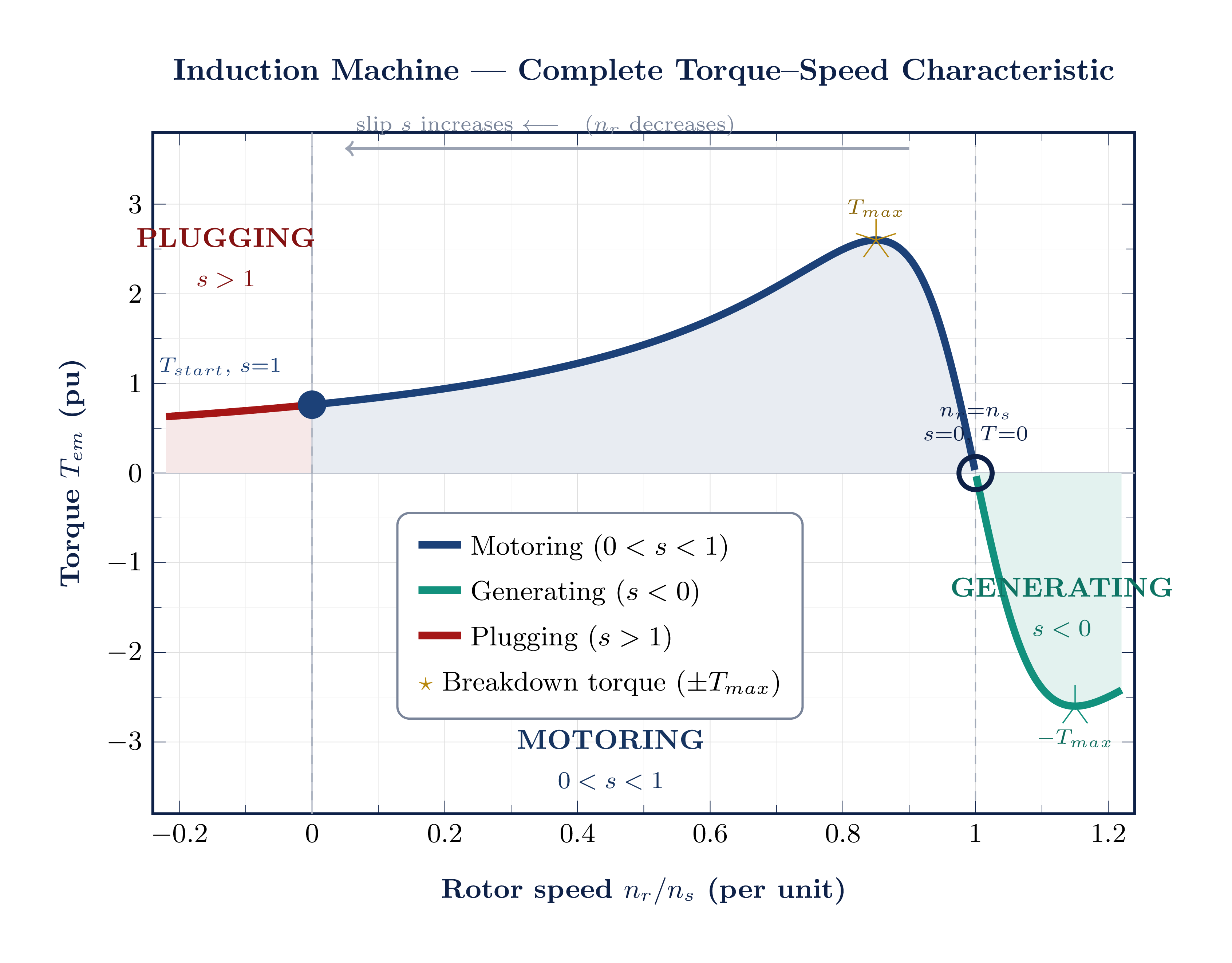
Operating Modes Based on Slip
| Mode | Slip s | Rotor Speed nr | Physical Condition |
|---|---|---|---|
| Standstill | s = 1 | nr = 0 | Locked rotor; starting condition |
| Motoring | 0 < s < 1 | 0 < nr < ns | Normal operation; motor drives load |
| Synchronous | s = 0 | nr = ns | Theoretical; zero torque, zero rotor loss |
| Generating | s < 0 | nr > ns | External prime mover; power fed to grid |
| Plugging | 1 < s < 2 | nr < 0 | Phase reversal; emergency braking |
Motoring: s = 0.005 → 0.08. Motor is self-regulating: ↑ load → ↑ slip → ↑ torque to match load.
Very high current and rotor losses. Used for fast stopping of high-inertia loads. Disconnect before rotor reverses.
Lecture Summary
- >90% of industrial motors are induction machines
- Self-starting, robust, VFD-compatible
- Stator: laminated core + 3-phase windings
- Rotor: squirrel cage (dominant) or wound
- Air gap: 0.5–2 mm, critical for coupling
- Spatial + temporal 120° displacement
- Rotates at ns = 120f/P rpm
- Speed fixed by supply frequency & pole count
- Field sweeps rotor conductors → induction
- Rotor currents + stator field → torque
- Rotor must slip below ns to sustain torque
- s = (ns − nr) / ns, fr = s · f
- Most important single operating variable
- Governs voltage, current, torque, losses
- Typical rated slip: 0.5% – 8%
The induction machine behaves like a transformer with a rotating secondary, leading to a slip-dependent rotor impedance Rr′/s — the foundation of the equivalent circuit (Lecture 5B).