Demonstrative Video
Excitation Systems
Small size SM field winding is generally excited from a separate DC source through slip-rings and brushes.
In large machines, various schemes are employed to supply DC excitation to the field winding.
Some of the most important excitation systems are:
DC Exciters
Static Excitation System
Brushless Excitation System
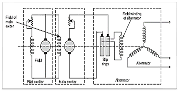
DC Exciters:
Conventional method of exciting the field windings
Three machines namely pilot exciter, main exciter & the main 3-phase alternator are mechanically coupled and are therefore, driven by the same shaft.
The pilot exciter is a DC shunt generator feeding the field winding of a main exciter.
Static Excitation System:
Excitation power for the main alternator field is drawn from output terminals of the main 3-phase alternator itself.
For this purpose, a three-phase transformer T1 steps down the alternator voltage to the desired value.
This three-phase voltage is fed to a three-phase full wave bridge rectifier using thyristors.
The firing angle of these thyristors is controlled by means of a regulator which picks up the signal from alternator terminals through potential transformer PT and current transformer CT.

Advantages of static excitation are:
Its response time is very small about 20 m sec.
It eliminates the exciter windage loss and commutator, bearing and winding maintenance.
As the excitation energy is taken from alternator terminals itself, the excitation voltage is directly proportional to alternator’s speed. This improves the overall system performance.
Brushless Excitation System:
Excitation system consists of an alternator, rectifier, main exciter and a pilot exciter (permanent magnet generator PMG).
Both the main exciter and pilot exciter are driven directly from the main shaft.
The AC output of PMG is rectified by three-phase full-wave phase controlled thyristor bridges.
The thyristor assembly is usually housed in removable drawers, which can be taken out easily for repair.

The thyristor bridges are controlled by a set of dual firing circuits operating in parallel.
The base excitation is controlled by an input setting to the thyristor gating circuits.
This control signal is derived from the PMG via a regulated DC supply, which also serves the regulator logic circuitry.
has a short time constant and a response time of less than 0.1 second.