Schottky & Varactor Diodes
Schottky Diodes – High-Speed Rectification
Problem with Ordinary Diodes at High Frequencies
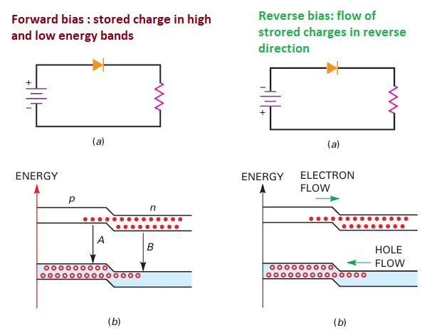
Charge Storage:
Small-signal diodes store charge in the p and n regions during forward conduction.
On switching to reverse bias, these stored charges result in reverse current for a short time.
Reverse Recovery Time (trr):
Time for reverse current to fall to 10% of forward current.
Example: 1N4148 has a trr = 4 ns, noticeable at frequencies above 10 MHz.
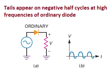
High-Frequency Rectification Issues:
At high frequencies, diodes exhibit reverse conduction tails, deteriorating rectification performance.
Key Features of Schottky Diodes
Eliminating Charge Storage:
Schottky diode uses a metal-semiconductor junction (gold, silver, or platinum + n-type silicon).
No depletion layer \(\rightarrow\) No stored charges \(\rightarrow\) No reverse recovery time.
Schottky Barrier:
0.25 V barrier created due to difference in electron orbit size between metal and semiconductor.
Efficient forward current conduction without charge storage.
Fast Turn-Off: Can switch off faster than ordinary diodes.
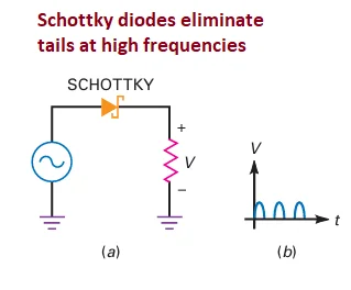
High-Frequency Operation:
Perfect half-wave rectification at frequencies above 300 MHz.
Ideal for high-speed switching applications.
Applications
Digital Computers:
Backbone of low-power Schottky TTLs used in digital circuits for faster switching.
High-frequency rectification circuits where fast response is critical.
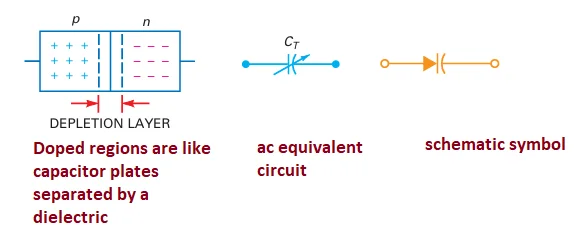
Varactor Diode – Voltage-Controlled Capacitance
Depletion Layer as Dielectric:
The p and n regions act like capacitor plates, and the depletion layer is the dielectric.
Reverse Bias increases depletion width, reducing capacitance.
Voltage-Controlled Capacitance:
The capacitance is inversely proportional to reverse voltage. As reverse voltage increases, capacitance decreases.
AC Equivalent Circuit: Acts like a variable capacitor for AC signals.
Schematic Symbol: A diode symbol with a capacitor in series, emphasizing its variable capacitance nature.
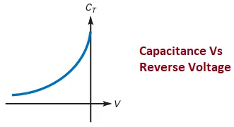
Capacitance vs. Reverse Voltage:
Capacitance decreases as reverse voltage increases.
This feature is used for electronic tuning in communication equipment like TVs and radios.
Varactor used in a parallel resonant circuit with an inductor.
The resonant frequency changes with reverse voltage.
Used in electronic tuning of radio stations, TV channels, etc.
Capacitance Ratio (CR):
Example: MV209 varactor has a capacitance of 29 pF at -3 V.
The capacitance decreases to 6 pF at -25 V, giving a ratio of 5:1.
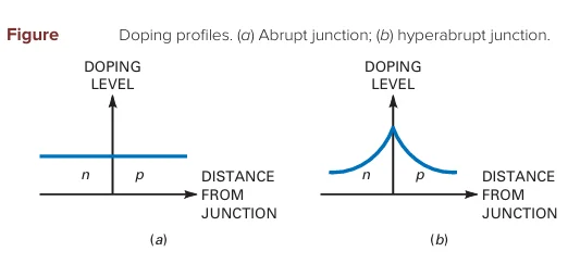
Doping Profiles:
Abrupt Junction: Uniform doping, typical tuning range of 3:1 to 4:1.
Hyperabrupt Junction: Heavily doped near the junction, allowing a 10:1 tuning range. Ideal for AM radios (535 to 1605 kHz).