To conduct open circuit and short circuit tests on a three-phase alternator and predetermine the percentage regulation curve by using the equivalent circuit parameters.

The voltage regulation of a synchronous generator (also known as alternator) is defined as the rise in voltage at the terminals when the load is reduced from full load (rated) value to zero, while the speed and field current are remaining constant at rated values.
% Regulation = { (Eo - V) / V } * 100
Eo – generated emf of alternator (or excitation voltage per phase)
V – full load, rated terminal voltage per phase
For small machines the regulation may be found by direct loading.
For large machines the voltage regulation is predetermined by using indirect methods like emf method, mmf method, Potier and ASA methods. All these methods require open circuit characteristics and short circuit characteristics.
In this experiment open circuit and short circuit tests will be conducted to determine the equivalent circuit parameters of the alternator and hence the internal voltage drop will be determined – this is also termed as EMF method.
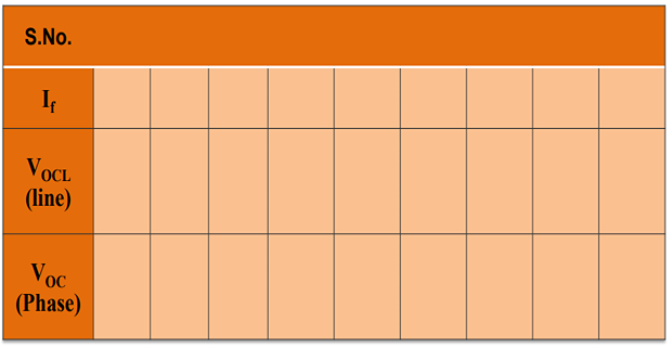
The open circuit characteristics (OCC) also called the magnetization curve; it is a plot of no load terminal voltage (generated emf) versus field excitation with the machine running at rated speed.
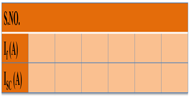
The short circuit characteristic (SCC) is a plot between armature current and field excitation with a symmetrical short circuit applied across the three-phase terminals of the alternator. Under these conditions, current in the armature winding completely depends on the internal impedance consisting of synchronous reactance Xs and the winding resistance Ra.
The air gap flux being very small, this operates in linear region (i.e., no saturation occurs). So, SCC is a straight line; only one point on SCC corresponding to ISCL = IFL needs to be determined experimentally.
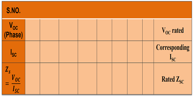
For any value of excitation or field current If, if VOC is the open circuit voltage per phase & Isc is the short circuit current, then synchronous impedance is,
Zs = Voc / Isc
The value of Zs is calculated for the unsaturated region before the magnetization curve reaches saturation.
For computing the Zs value at rated conditions, get the field current corresponding to rated voltage of the alternator from OCC (If rated); then extrapolate the SCC and get the value of short circuit current corresponding to this If rated.
The armature resistance (Ra) is measured using ammeter-voltmeter method or by using a multi-meter. Now,
(Zs2 – Ra2) = Xs2
Under working conditions, the effective value of Ra is increased due to skin effect and temperature effect. The effective value of Ra is generally taken as 1.3 times the DC value measured using multi-meter.
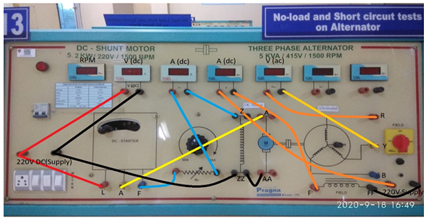
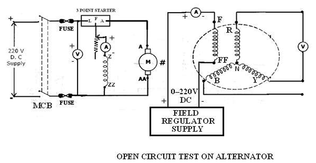
- Supply Positive to 3 Point Starter L
- Supply Positive to Voltmeter Terminal (Red)
- 3 Point Starter F to Rheostat Terminal (Red)
- Rheostat Terminal (Black) to Ammeter Terminal (Red)
- Ammeter Terminal (Black) to Field Terminal Z
- 3 Point Starter L to Motor Terminal A
- Supply Negative Terminal (Black) to Voltmeter Terminal (Black)
- Supply Negative Terminal (Black) to Motor Field Terminal ZZ
- Motor Field Terminal ZZ (Black) to Motor Armature Terminal AA
- Field Regulator Supply Terminal (Red) to Ammeter Terminal (Red)
- Ammeter Terminal (Black) to Alternator Field Terminal F
- Field Regulator Supply Terminal (Black) to Alternator Field Terminal FF
- Alternator Terminal R to AC Voltmeter Terminal (Red)
- Alternator Terminal Y to AC Voltmeter Terminal (Black)
- Alternator Terminal Y to Alternator Terminal B Open
- Connect the circuit.
- Motor field rheostat must be kept in minimum resistance position. Alternator field switch should be kept at off position; field regulator of alternator should be kept in minimum output position.
- Switch ON the MCB, start the Motor-Alternator set using the 3-point starter.
- Adjust the field rheostat of the motor in order to bring the Motor-Alternator set to rated speed i.e., 1500 rpm.
- Switch on the field supply to the alternator and vary the field regulator (This is a variac connected with a rectifier; so, variac output voltage is to be varied) in steps; note the field current (If) and generated output voltage (VG) until the VG reaches rated value i.e., 415 V.
- Bring back the field supply regulator to minimum output position; switch off the field supply to the alternator and keep the rheostat as in step (2).
- Switch off the MCB.
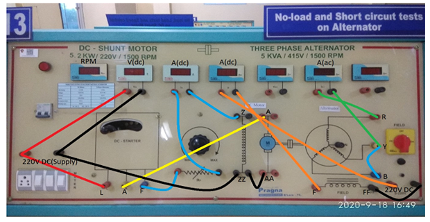
- Supply Positive to 3 Point Starter L
- Supply Positive to Voltmeter Terminal (Red)
- 3 Point Starter F to Rheostat Terminal (Red)
- Rheostat Terminal (Black) to Ammeter Terminal (Red)
- Ammeter Terminal (Black) to Field Terminal Z
- 3 Point Starter L to Motor Terminal A
- Supply Negative Terminal (Black) to Voltmeter Terminal (Black)
- Supply Negative Terminal (Black) to Motor Field Terminal ZZ
- Motor Field Terminal ZZ (Black) to Motor Armature Terminal AA
- Field Regulator Supply Terminal (Red) to Ammeter Terminal (Red)
- Ammeter Terminal (Black) to Alternator Field Terminal F
- Field Regulator Supply Terminal (Black) to Alternator Terminal FF
- Alternator Terminal R to AC Ammeter Terminal (Red)
- Alternator Terminal Y to AC Ammeter Terminal (Black)
- Alternator Terminal Y to Alternator Terminal B
- Connect the circuit.
- Motor field rheostat must be kept in minimum resistance position. Alternator field switch should be kept at off position; field regulator of alternator should be kept in minimum output position.
- Switch ON the MCB, start the Motor-Alternator set using the 3-point starter.
- Adjust the field rheostat of the motor in order to bring the Motor-Alternator set to rated speed i.e., 1500 rpm.
- Switch on the field supply to the alternator and by varying the field regulator in steps, vary the field current; note the field current (If) and short circuit current of the alternator (IG) until IG reaches its rated value of 6.9 A.
- Bring back the field supply regulator to minimum output position; switch off the field supply and keep the rheostat as in step (2); switch OFF the MCB.
- Measure the armature resistance across R and N terminals of the alternator using a multimeter after disconnecting all the extra connections to the alternator.
Measure DC armature resistance Ra across R and N terminal of alternator using a multimeter R a(dc) = -------
Effective resistance Re:-----------------=1.3 × Ra(dc)
FORMULAE:
Zs = (Voc/Isc) for the particular If and speed.
Xs = √(Zs2 – Re2)
[where Re = AC armature resistance]. For voltage regulation computation, choose the least value of Zs obtained from the above table.
Generated emf of the alternator on full-load is,
E0 = √((V cos Φ + Ia Re)2 + (V sin Φ ± Ia Xs)2)
where,
- V = Full-load terminal voltage
- Ia = Armature current of the alternator
- cos Φ = Load Power factor
(+ sign for lagging PF load and - sign for leading PF load)
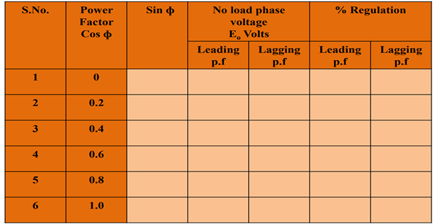
The percentage regulation of the alternator for a given p.f. is,
% Regulation = (E0 - V) / V * 100
Where,
- E0 - generated emf of alternator (or excitation voltage per phase)
- V - full load, rated terminal voltage per phase
Plot the OCC and SCC on common \(I_f\) as shown in model graph
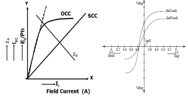
The graphs are drawn between:
- VOCL vs If
- ISCL vs If
- ZS vs If
- Regulation vs p.f
- Percentage Regulation at Full-load upf =
- at Full-load 0.8pf lag =
- at Full-load 0.8pf lead =
- Define synchronous impedance.
- The voltage regulation will be positive, negative, and zero under which conditions?
- The regulation is maximum under which load p.f.?
- What is skin effect?
- Why is the SCC a straight line?