OBJECTIVE:
To draw the equivalent circuit of a 3 phase induction motor and to obtain its performance characteristics by conducting No-load and blocked rotor tests.
NAME PLATE DETAILS:
|
NAME PLATE DETAILS OF 3ɸ SQUIRREL CAGE INDUCTION MOTOR |
|
|
KW Rating |
5 HP/ 3.5 KW, 0.86pf |
|
Voltage |
415 V AC, 50 Hz |
|
Current |
7 A |
|
Speed |
1440 RPM |
|
Winding type |
Squirrel Cage |
|
starter Resistance |
5.8 Ω (R-N) |
|
Brake Drum Radius: 0.1 M |
|
APPARATUS REQUIRED:
|
S.No. |
Name of the Equipment |
Range |
Quantity |
Type |
|
1. |
Voltmeter |
500 VAC |
1 No |
Digital |
|
2. |
Ammeter |
20 A |
1 No |
Digital |
|
3. |
Wattmeter |
150/300 V 20 A |
1 No |
Digital |
|
4. |
Three phase variac |
0 - 415V 20 A |
1 No |
Core |
|
5. |
Tachometer |
2000 Rpm |
1 No |
Digital |
INTRODUCTION:
- An induction machine can be viewed as a generalized transformer
where the rotor (secondary) voltage and frequency both vary, both of
them being directly proportional to the rotor slip where,
Slip = (synchronous speed Ns − Rotor speed Nr)/Ns
- The mechanical power developed is the difference between the air gap
power and the rotor copper loss.

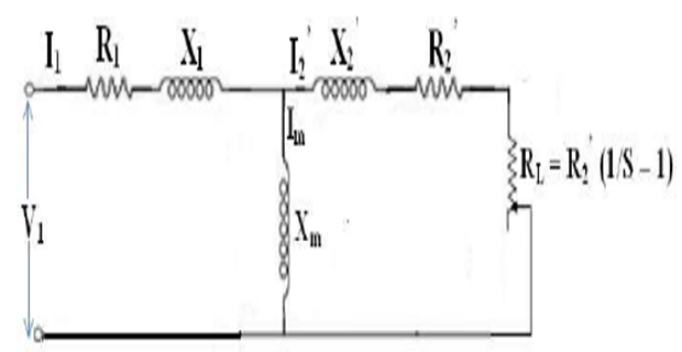
- The load resistance represents the mechanical power developed. The equivalent circuit parameters can be determined by No load test and Blocked – Rotor test.
NO LOAD TEST::
- At no load the machine runs freely with a very small slip which is sufficient to provide power for windage and friction loss, core loss and also a certain amount of stator copper loss which has to be accounted for because of relatively larger no load current (as compared to a transformer).
- With low slip, and hence the rotor circuit is literally open making the rotor current zero.(ℝ2’/ s) > > 𝕏2’
- With these approximations the necessary formula for finding out \(X_m\) will be given later under procedure for conducting the no – load test
BLOCKED ROTOR TEST:
- Blocking the rotor from rotating is equivalent to making s = 1 so that,
R2′(1/s − 1) = 0
- Mechanical power developed is zero at this point.
- This test is conducted by applying a low voltage to the stator so as to limit the current drawn to its full load value.
- At this reduced voltage, core loss can be neglected (because flux is low as [V/f] is low); but the effect of \(X_m\) has to be taken into account as its value is small as compared to that of a transformer of comparable rating.
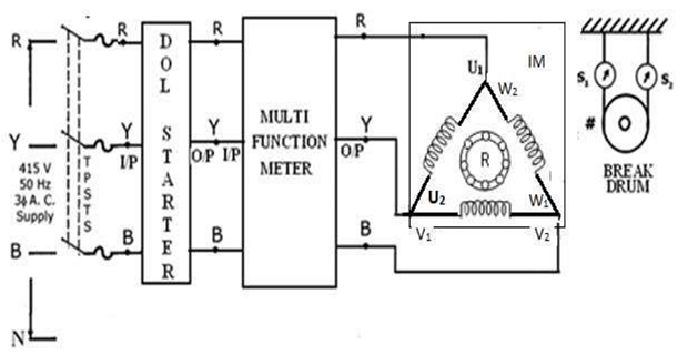
CIRCUIT DIAGRAM FOR NO LOAD TEST:
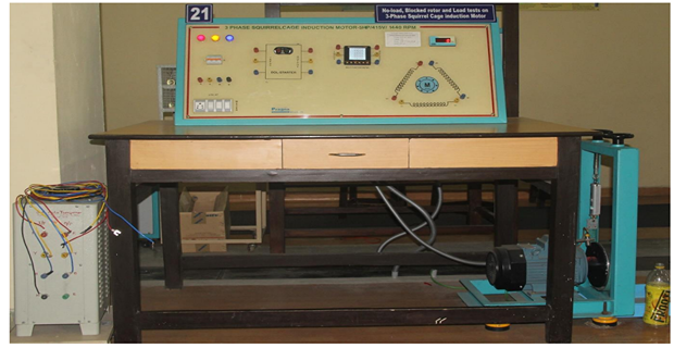
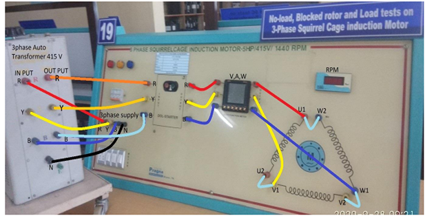
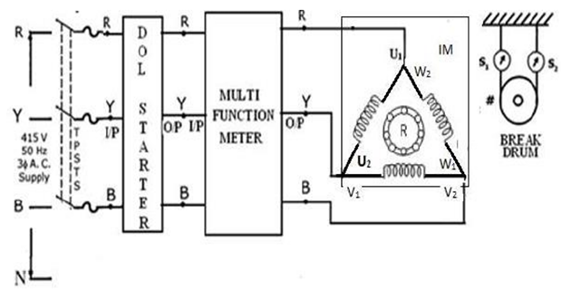
EM LAB SET-UP:
CONNECTION FOR NO-LOAD TEST:
- 3ɸ AC Supply R to DOL Starter Input R
- 3ɸ AC Supply Y to DOL Starter Input Y
- 3ɸ AC Supply B to DOL Starter Input B
- DOL Starter Output R to Multi-Function Meter Input R
- DOL Starter Output Y to Multi-Function Meter Input Y
- DOL Starter Output B to Multi-Function Meter Input B
- Multi-Function Output R to Induction Motor U1
- Multi-Function Output Y to Induction Motor V1
- Multi-Function Output B to Induction Motor W1
- Connect U1 to W2, V1 to U2 and W1 to V2
PROCEDURE FOR NO-LOAD TEST:
- Connect the circuit diagram.
- Ensure that the motor is unloaded and switch on MCB, start the motor with the help of Direct On Line (D.O.L) starter.
- Motor starts to run at rated speed note down the No-load Voltage (Vo), Current (Io), Power (Wo) from the multi-function meter.
- Push OFF button (Red button) in the D.O.L starter, switch off the MCB.
- Measure R1 the stator resistance per phase using multimeter.
OBSERVATION TABLE:
|
S.No. |
V0(V) |
I0(A) |
W0(three phase) |
|
|
|
|
|
MODEL CALCULATION:
NO LOAD TEST:-
- To obtain no load current and its p.f angle \(\phi_0\), no load test is performed at rated voltage and frequency. Let the readings of ammeter, voltmeter and wattmeter connected in circuit be \(\mathrm{I}_0, \mathrm{~V}_0 \) and \(\mathrm{W}_0\) respectively during no load test.
- \( \mathrm{W}_0\) is the 3-phase power consumed by the motor which includes stator copper losses, iron loss and windage and friction loss. However, rotor copper and core losses are negligible.
CIRCUIT DIAGRAM FOR BLOCKED ROTOR TEST::
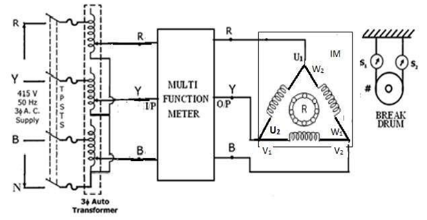
CONNECTION FOR BLOCKED ROTOR TEST:
- 3ɸ AC Supply to 3ɸ Auto VARIAC Input Terminal R
- 3ɸ AC Supply to 3ɸ Auto VARIAC Input Terminal Y
- 3ɸ AC Supply to 3ɸ Auto VARIAC Input Terminal B
- 3ɸ Auto VARIAC Output Terminal R to Multi-Function Meter Input R
- 3ɸ Auto VARIAC Output Terminal Y to Multi-Function Meter Input Y
- 3ɸ Auto VARIAC Output Terminal B to Multi-Function Meter Input B
- Multi-Function Output R to Induction Motor U1
- Multi-Function Output Y to Induction Motor V1
- Multi-Function Output B to Induction Motor W1
- Connect U1 to W2, V1 to U2 and W1 to V2
PROCEDURE FOR BLOCKED ROTOR TEST:
- Connect the circuit diagram.
- Block the rotor by tightening the belt.
- Switch ON the MCB and apply the voltage gradually by increasing the output of the 3ɸ VARIAC so that the current drawn by the motor under blocked rotor condition is equal to the full load current of the motor.
- Record the reading of Blocked rotor Voltage (\(V_{BRL}\)), Current (\(I_{BRL}\)), Power (\(W_{BRL}\)) from the multi-function meter.
- Unload the motor by loosening the belts, reduce the applied voltage to zero by varying the three-phase VARIAC and switch OFF the MCB.
OBSERVATION TABLE:
|
S.No. |
VBRL(V) |
IBRL(A) |
WBR (three phase) |
|
|
|
|
|
- Stator resistance can be measured using a multimeter as \(R_m\)
- If the stator is a star connected one, then, \(R_1\) per phase = \(\frac{R_m}{2}\)
- If the stator is a delta connected one, then \(R_1\) per phase = \(\frac{3}{2} \cdot R_m\)
- However, the above value is DC resistance. \(R_{\text{dc}} = \frac{3}{2} \cdot R_m\)
- To compute AC resistance \(R_1 = R_{\text{ac}} = 1.3 \cdot R_{\text{dc}}\)
MODEL CALCULATIONS:
BLOCKED ROTOR TEST:
In the above circuit the stator is connected in delta
- Motor equivalent impedance referred to stator \(Z_{\mathrm{BR}}\) per phase = \(\frac{V_{\mathrm{BR}}}{I_{\mathrm{BR}}}\)
-
Motor equivalent resistance referred to stator \(R_{\mathrm{BR}}\) = \(Z_{\mathrm{BR}} \cos(\varphi_{\mathrm{BR}})\)
= \(\frac{W_{\mathrm{BR}}}{3 I_{\mathrm{BR}}^2}\) - \(R_{\mathrm{BR}} = R_1 + R_2'\) = Sum of series resistances in the stator and rotor (referred to stator)
- Motor equivalent reactance referred to stator \(X_{\mathrm{BR}}\) = \(\sqrt{Z_{\mathrm{BR}}^2 - R_{\mathrm{BR}}^2}\)
- \(X_{\mathrm{BR}} = Z_{\mathrm{BR}} \sin(\varphi_{\mathrm{BR}}) = X_1 + X_2'\) = Sum of leakage reactances of the stator and rotor (referred to stator)
- Rotor resistance referred to stator \(R_2' = R_{\mathrm{BR}} - R_1\)
- Rotor reactance referred to stator \(X_2' / 2 = X_1\)
-
\(R_1\) = stator resistance
\(X_1\) = stator reactance - Equivalent load resistance \(R_{\mathrm{L}} = R_2' (1/S - 1)\)
-
Slip = \(\frac{N_s - N}{N_s}\)
\(N_s\) = synchronous speed
\(N\) = speed of the motor
To estimate the performance at any rotor speed N rpm
Rated line voltage applied to the stator = \( V \); Let the phase voltage be \( V_{\text{ph}} \)
- Rotor impedance per phase \( Z_2' = \left( \frac{R_2'}{s} \right) + jX_2' \)
- Rotor current (approximately) \( I_2' = \left( \frac{V_{\text{ph}}}{Z_2'} \right) \angle \left( \tan^{-1} \left( \frac{sX_2'}{R_2'} \right) \right) = I_2' \angle -\phi_2 \)
- Rotor input power \( P_g = 3I_2'^2 R_2' / s \)
- Rotor copper losses \( P_{\text{cu}} = 3I_2'^2 R_2' \)
- Therefore, Rotor output power \( P_g - P_{\text{cu}} = P_g (1-s) = P_{\text{out}} \)
- No-load current = \( I_0 \angle -\phi_0 \)
- Total stator side current \( I_1 \) = Vectorial addition of no-load and rotor current
\( I_1 = I_0 \angle -\phi_0 + I_2' \angle -\phi_2 = I_1 \angle -\phi_1 \) - Input power \( 3V_{\text{ph}} I_1 \cos \phi_1 = P_{\text{in}} \)
- Efficiency \( \eta = \frac{P_{\text{out}}}{P_{\text{in}}} \)
- Power Factor = \( \cos \phi_1 \)
- Torque \( T = \frac{P_{\text{out}}}{\omega} \) where \( \omega = \text{rotor speed in radians per sec} = \frac{2\pi N}{60} \)
OBSERVATION TABLE:
|
Speed N |
Ns |
0.99Ns |
0.98 Ns |
0.97Ns |
0.96Ns |
0.95Ns |
0.9 Ns |
0.7 Ns |
0.5 Ns |
0.3 Ns |
0.1 Ns |
0 |
|
Slip ‘s’ |
0 |
0.01 |
0.02 |
0.03 |
0.04 |
0.05 |
0.1 |
0.3 |
0.5 |
0.7 |
0.9 |
1 |
|
Z2’= (R2’/s) + jX2’ |
|
|
|
|
|
|
|
|
|
|
|
|
|
I2’ |
|
|
|
|
|
|
|
|
|
|
|
|
|
Pg |
|
|
|
|
|
|
|
|
|
|
|
|
|
Pcu |
|
|
|
|
|
|
|
|
|
|
|
|
|
Pout |
|
|
|
|
|
|
|
|
|
|
|
|
|
I1 |
|
|
|
|
|
|
|
|
|
|
|
|
|
Pin |
|
|
|
|
|
|
|
|
|
|
|
|
|
Efficiency η |
|
|
|
|
|
|
|
|
|
|
|
|
|
PF Cosϕ1 |
|
|
|
|
|
|
|
|
|
|
|
|
|
Torque T |
|
|
|
|
|
|
|
|
|
|
|
|
Equivalent circuit of the induction motor under test:
GRAPHS::
Draw the graphs between
- Line current (\(I_1\)) vs. Slip
- Torque vs. Slip and rotor speed
- Power factor vs. Slip
- % efficiency (\(\eta\)) vs. Slip
- % efficiency (\(\eta\)) vs. \(P_{\text{out}}\)
RESULT::
- Complete the performance characteristics of the given 3 – phase Induction Motor
OBJECTIVE FOR LOAD TEST
To obtain the performance characteristics of 3 – phase induction motor by Load test and by loss summation method
CIRCUIT DIAGRAM FOR LOAD TEST
INTRODUCTION:
- On no load, the power factor of an induction motor is very low, and it slowly improves with the load and attains a value around 0.85 on full load.
- Efficiency starts from zero on no load; increases with load, reaches a maximum at about 80% of rated load and then starts decreasing.
THEORY:
- The a.c. motors are classified as single and three phase induction motors, synchronous motors, and some special purpose motors.
- Out of all these types, three phase induction motors are widely used for various industrial applications.
- The important advantages of three phase induction motors over other types are self-starting property, fairly good power factor, good speed regulation, and robust construction.
- The working principle of three phase induction motors is based on the production of rotating magnetic field.
CONNECTION:

- 3ɸ AC Supply R to DOL Starter Input R
- 3ɸ AC Supply Y to DOL Starter Input Y
- 3ɸ AC Supply B to DOL Starter Input B
- DOL Starter Output R to Multi-Function Meter Input R
- DOL Starter Output Y to Multi-Function Meter Input Y
- DOL Starter Output B to Multi-Function Meter Input B
- Multi-Function Output R to Induction Motor \( U_1 \)
- Multi-Function Output Y to Induction Motor \( V_1 \)
- Multi-Function Output B to Induction Motor \( W_1 \)
- Connect \( U_1 \) to \( W_2 \), \( V_1 \) to \( U_2 \), and \( W_1 \) to \( V_2 \)
PROCEDURE:
- Connect the circuit as per the circuit diagram.
- Switch ON the MCB and start the induction motor with the help of the D.O.L starter.
- Induction motor starts to rotate at rated speed.
- Note down the readings of wattmeter, ammeter, and voltmeter on no-load.
- The induction motor current is increased by tightening the brake drum till the rated current is attained. At each current, Voltage (V), Current (IL), Power input (Pin), Speed (N), S1 & S2 (spring balance readings) are noted.
- Reduce the load on the motor and finally unload it completely, then press the starter ‘stop’ button and turn off the MCB.
- Note down the effective diameter of the brake drum in meters (R).
OBSERVATION TABLE:
Constant losses
\( P_{\text{const}} = \text{No load input power} – \text{corresponding input power during no-load test} \)
M. F. = Multiplication factor of Wattmeter = \( \left(\frac{VI \cos \varphi}{\text{FSD}}\right) \)
FSD = Full scale divisions
|
S.NO. |
V |
IL |
PIN |
N |
Spring Balance |
T |
PO |
Slip |
PF |
% η |
||
|
S1 |
S2 |
S1-S2 |
||||||||||
|
|
|
|
|
|
|
|
|
|
|
|
|
|
|
|
|
|
|
|
|
|
|
|
|
|
|
|
|
|
|
|
|
|
|
|
|
|
|
|
|
|
MODEL CALCULATIONS:
MODEL GRAPH:

Draw the graphs between
- % efficiency (\(\eta\)) Vs Output
- Torque Vs Output
- Power factor Vs Output
- % Slip Vs Output
- Torque Vs Slip ( on a separate sheet )
Result:
|
LOAD |
EFFICIENCY |
PF |
SLIP |
LINE CURRENT |
|
1/4 |
|
|
|
|
|
1/2 |
|
|
|
|
|
3/4 |
|
|
|
|
|
FULL LOAD |
|
|
|
|
QUESTIONS:
- What are the methods of starting induction motor?
- What are the types of induction motor?
- Why is a cage motor preferred as compared to the slip ring motor?
- What are the differences in characteristics obtained from load test and performance prediction using equivalent circuit?