Demonstrative Video
SYNCHRONIZATION OF AN ALTERNATOR
OBJECTIVE:
- To synchronize the alternator with the infinite bus
- To determine and plot the V-curves and inverted V-curves of a synchronous motor under constant power operation
NAME PLATE DETAILS:
|
NAME PLATE DETAILS OF DC SHUNT MOTOR & ALTERNATOR |
||
|
|
DC Motor |
3-Phase Alternator |
|
KW Rating |
5.2 KW |
6.5 KVA/5.2 KW |
|
Voltage |
220 V DC |
415 V AC 50 Hz |
|
Current |
20 A |
9 A |
|
Speed |
1500 RPM |
1500 RPM |
|
Excitation current |
0.9 A |
5.8 A |
|
Winding type |
Shunt |
Salient pole |
|
|
Ra : 2.7 Ω , Rsh : 179 Ω |
R - N = 2.6 Ω |
APPARATUS REQUIRED:
|
S.No. |
Name of the Equipment |
Range |
Quantity |
Type |
|
1. |
Voltmeter |
300 VDC |
1 No |
Digital |
|
2. |
Voltmeter |
500 VAC |
1 No |
Digital |
|
3. |
Ammeter |
20 ADC |
2 Nos |
Digital |
|
4. |
Ammeter |
20 AAC |
1 No |
Digital |
|
5. |
Rheostat |
360Ω/1.6A |
1 No |
Coil |
|
6. |
Tachometer |
2000 Rpm |
1 No |
Digital |
THEORY: SYNCHRONIZATION
- Often electrical generators are removed from the service and connected back to the power system during variations of the load, emergency outages, maintenance, etc.
- Before reconnecting the generator to the system each time, it must be synchronized with parameters of the power system network.
- An improper synchronization can affect the healthy power system and result in electrical and mechanical transients that can damage the prime mover, generator, transformers, and other power system components.
- The process of matching parameters such as voltage, frequency, phase angle, phase sequence, and waveform of alternator (generator) or other source with a healthy or running power system is called synchronization.
- The purpose of synchronization is to ensure that at the moment of closing the circuit breaker (closing the 3-pole single throw switch to connect the alternator to the grid in this experiment), the voltages across the three phases of the breaker are as close to zero as possible and remain so after the switch is closed.
Following conditions should be met:
- Generated voltage must be approximately equal to the grid voltage.
- Frequency of the generated voltage must be equal to that of the grid.
- Phase sequence of the generated voltage must be the same as that of the grid.
- Phase of the generated voltages relative to some reference must be very close to the phase of grid lines.
Fulfillment of these conditions is checked by the dark lamp method and via synchroscope.
SYNCHRONIZATION BY DARK LAMP METHOD:
- A set of three synchronizing lamps can be used to check the conditions for paralleling or synchronization of the incoming machine with the other machine/bus bar. A dark lamp method along with a voltmeter used for synchronizing is shown in the Figure.
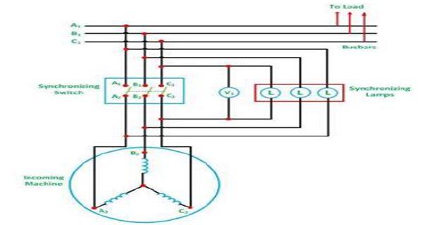
- The prime mover of the incoming machine is started and brought nearer to its rated speed.
- A field current of the incoming machine is adjusted in such a way so that it becomes equal to the bus voltage.
- The flicker of the three lamps occurs at a rate which is equal to the difference in the frequencies of the incoming machine and the bus.
- All the lamps will glow and turn off at the same time if the phases are properly connected.
- If the above condition is not satisfied, then the phase sequence is not connected correctly.
- Thus, in order to connect the machine in the correct phase sequence, two leads to the line of the incoming machine should be interchanged.
- The frequency of the incoming machine is adjusted until the lamp flicker at a slow rate. The flicker rate should be less than one dark period per second.
- After finally adjusting the incoming voltage, the synchronizing switch is closed in the middle of their dark period. At this moment, the synchronizing switch is closed and the generator is synchronized with the mains.
V-curves and inverted V-curves of a synchronous motor:
- A synchronous motor is a double-excited machine, its armature winding is energized from an AC source and its field winding from a DC source.
- Synchronous motor operates at unity power factor when field current is enough to set up the air-gap flux, as demanded by constant applied voltage.
- This field current, which causes unity power factor operation of the synchronous motor, is called normal excitation or normal field current.
- If the motor is under-excited, i.e., current is less than normal excitation, there will be some deficiency in flux.
- To compensate, the winding draws a magnetizing current from the AC source and as a result, the motor operates at a lagging power factor.
- In the other case, if over-excited, i.e., field current more than normal excitation, the machine operates at leading power factor. In the figure below, you can observe leading and lagging variations.
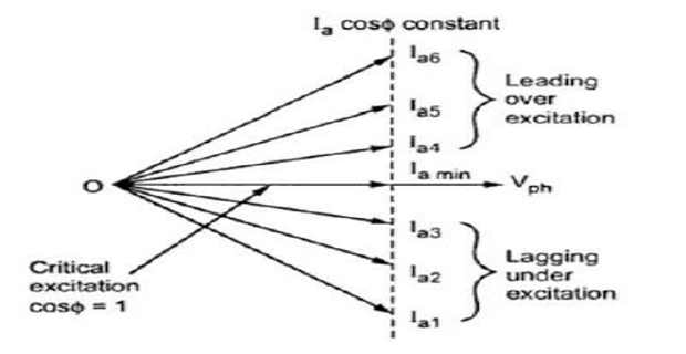
- In synchronous motors, performance characteristics are obtained by V-curves and inverted V-curves. Synchronous machines have parabolic type characteristics.
- If excitation is varied from very low (under-excitation) to very high (over-excitation) value, then current \(I_a\) decreases, becomes minimum at unity p.f., and then again increases.
- But initial lagging current becomes unity and then becomes leading in nature. V-curves and inverted V-curves are used to analyze motor efficiency with no-load and with load.
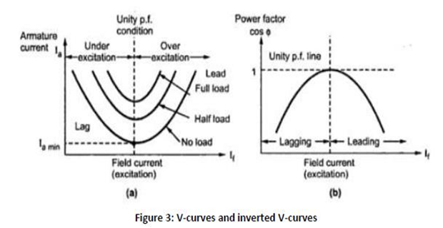
- For a synchronous motor, the armature current phasor is given by:
\(I_a = \dfrac{V-E}{Z_s}\)Where,
- V is the applied voltage phasor and is a constant when the motor is connected to an infinite bus.
- E is the induced emf phasor, the magnitude of which depends on the DC excitation.
- Zs is synchronous impedance.
Equipment and Components Required:
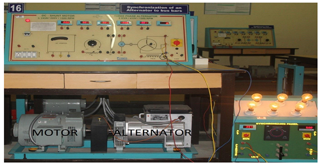
- Synchronous machine coupled to a DC machine.
- DC/AC ammeters and voltmeters.
- Two wattmeters with reversing switch.
- Rheostat of suitable range for field control synchronizing board.
- Tachometer.
CIRCUIT DIAGRAM:
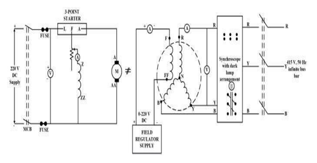
EM LAB SET-UP:
CONNECTION FOR SYNCHRONIZATION:
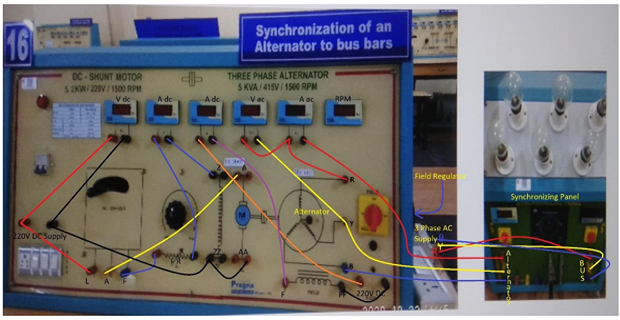
- Supply Positive Terminal to Voltmeter Terminal (Red)
- Supply Positive Terminal to 3-Point Starter Terminal L
- 3-Point Starter Terminal F to Rheostat Terminal (Red)
- Rheostat Terminal (Black) to Ammeter (1) Terminal (Red)
- Ammeter (1) Terminal (Black) to Motor Field Z
- 3-Point Starter Terminal A to Motor Armature A
- Supply Negative Terminal to Voltmeter Terminal (Black)
- Supply Negative Terminal to Motor Terminal Field ZZ
- Motor Field Terminal ZZ (Black) to Motor Armature Terminal AA
- Field Regulator Supply Terminal (Red) to Ammeter Terminal (Red)
- Ammeter Terminal (Black) to Alternator Field Terminal F
- Field Regulator Supply Terminal (Black) to Alternator Terminal FF
- Alternator Terminal R to AC Ammeter Terminal (Red)
- AC Ammeter Terminal (Black) to Synchronous Switch Output R
- Alternator Terminal R to AC Voltmeter Terminal (Red)
- Alternator Terminal Y to AC Voltmeter Terminal (Black)
- Alternator Terminal Y to Synchronous Switch Output Y
- Alternator Terminal B to Synchronous Switch Output B
- 3ɸ AC Supply R to Synchronous Switch Input R
- 3ɸ AC Supply Y to Synchronous Switch Input Y
- 3ɸ AC Supply B to Synchronous Switch Input B
PROCEDURE FOR V CURVES:
- Connect the circuit.
- Motor field rheostat must be kept in minimum resistance position. Alternator field switch should be kept at off position; field regulator of alternator should be kept in minimum output position.
- Switch ON the MCB, start the Motor-Alternator set using the 3-point starter.
- Adjust the field rheostat of the motor in order to bring the Motor-Alternator set to rated speed i.e., 1500 rpm.
- Switch on the field supply to the alternator and vary the field regulator (This is a variac connected with a rectifier; so, VARIAC output voltage is to be varied) in steps; note the field current (If) and generated output voltage (VG) until the VG reaches rated value i.e., 415 V.
- Synchronize the alternator to the mains. For this purpose, make sure that the magnitudes, the phase, phase sequence, and frequency of the alternator terminal voltage and the infinite bus voltage are matched.
- Synchronize synchronous machine with the three-phase grid using the 3-lamp method.
- Connect lamps in between the 3-phase terminals of the alternator and the AC mains. If the lamps are glowing, this indicates that there is a voltage difference between the AC mains voltage and the alternator terminal voltage. By adjusting the excitation, the voltage magnitudes can be matched (let’s say it is (\(V/\sqrt{2}\)).
- If the speed of the DC motor is adjusted, then the frequency of the generated voltage of the alternator can be adjusted. If w1 is the frequency of the generated voltage and ws is the frequency of the AC mains voltage, as long as the difference between the two frequencies (ws and w1) is very low (which can be achieved by adjusting the speed of the DC motor), the lamps will have an oscillatory illumination; that is, they will go from a huge brightness to darkness and vice versa. Adjust the speed of the DC motor such that this oscillation in the illumination becomes very slow; this will be visible in the synchroscope in the form of a red colored LED light moving in the anticlockwise direction slowly. When both the voltages are matching exactly, then the lamps will be dark and the LED will be glowing green and will come to the 12 O’ clock position in the clock.
- Dark Lamp method: when all the lamps are completely dark, at which time all the voltages of the bus are exactly in phase with the corresponding voltages of the generator. At this moment the synchronizing switch is closed and the generator is synchronized with the mains.
- Disconnect the DC machine’s armature from the DC mains. Now the synchronous machine is working as a synchronous motor and the DC machine functions as a generator. At no-load (without taking any output from the coupled DC machine) vary the field current of the synchronous machine with the help of sliding rheostat and correspondingly record the armature current. If we adjust the field current of the alternator at this juncture, we would see that its armature current follows a ‘V’ shape. i.e, when \(I_f\) value is 0.8A, \(I_a\) may be 4 A; as we increase \(I_f\) from 0.8 towards 1.2 A, the \(I_a\) value may go down to 2.5 A or so and when \(I_f\) varies further to 1.5 A or 2 A, again \(I_a\) will go up and reach 3.5 or 4 A; thus \(I_a\) vs. \(I_f\) variation follows a ‘V’ shape.
PROCEDURE FOR INVERTED V CURVES:
- Measure the power factor using a power factor meter or estimate the power factor using the 2-wattmeter method.
- Vary the field excitation and measure its values.
- Draw the curve between \(I_f\) and \(\cos\phi\) to obtain the Inverted-V curve.
OBSERVATION TABLE:
Table: Reading with constant Power (Constant Power = 0 kW)
|
S. No. |
If (A) |
Ia (A) |
|
|
|
|
|
|
|
|
|
|
|
|
|
|
|
|
|
|
|
|
|
|
|
|
|
|
|
|
|
|
|
|
|
|
|
|
|
|
|
|
QUESTIONS:
- State the conditions for synchronization of two alternators.
- State the effect of wrong synchronization.
- State why a pair of lamps are required in the lamp method of synchronization?
- Explain the necessity of synchronization of alternators.
- State the advantages of using a number of small generating units instead of a single large unit for supplying power.
- Why is the frequency of the incoming alternator kept slightly higher than the bus-bar frequency?
- What is the difference between a synchronous motor and a synchronous condenser?
- For the given test setup, how can you make the synchronous machine become a generator feeding power to the bus?
- If the two 400V machines are to be synchronized by either the dark lamp or bright lamp method, what will be the voltage rating of the bulb?
- What is a synchroscope?
- Will the UPF always occur at a particular value of field current for a synchronous motor irrespective of the power it is delivering?
- Why is the armature current minimum at the UPF condition?