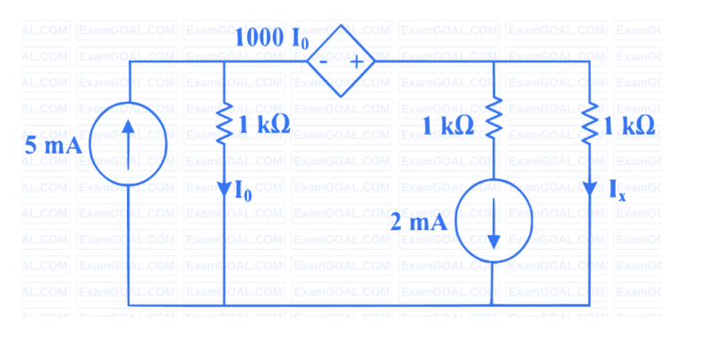
In the given circuit, the current \(I_x\) (in mA) is _____.
Circuit for GATE 2024 Electric Circuits Q1
Solution
This circuit is best solved using a super node around the dependent voltage source.
Let \(V_1\) and \(V_2\) be the node voltages at the two ends of the dependent source.
The super node equation (KCL) is:
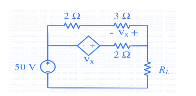
In the network shown below, maximum power is to be transferred to the load \(R_L\). The value of \(R_L\) (in \(\Omega\)) is _____.
Circuit for GATE 2024 Electric Circuits Q2
Solution
For maximum power transfer, \(R_L = R_{TH}\). We find \(R_{TH}\) by applying a test source \(V_{dc}\) at the load terminals (with the 50V source shorted) and finding \(I_{dc}\). \(R_{TH} = V_{dc} / I_{dc}\).
The parameter \(Y_{21} = \frac{12}{8} = \frac{3}{2} = 1.5\) S.
✓
Final Answer
Correct answer: 1.5.
Question 04
Question 4
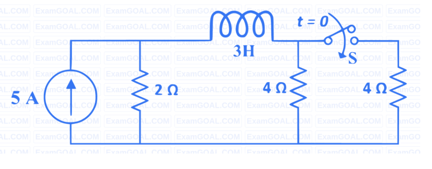
In the circuit given below, the switch S was kept open for a sufficiently long time
and is closed at time \(t=0\). The time constant (in seconds) of the circuit for \(t>0\) is _____.
Circuit for GATE 2024 Electric Circuits Q4
Solution
For \(t \ge 0\), the switch is closed. The time constant \(\tau\) for an R-L network is \(\tau = L/R_{TH}\).
\(R_{TH}\) is the Thevenin resistance across the inductor (L) when all independent sources
are deactivated (current source becomes open circuit).
Looking into the terminals of the inductor: The 2\(\Omega\) resistor is in series with the
parallel combination of the two 4\(\Omega\) resistors.
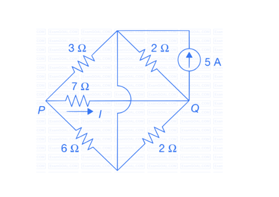
Consider the circuit shown in the figure. The current I flowing through the 7\(\Omega\)
resistor between P and Q (rounded off to one decimal place) is ____ A.
Circuit for GATE 2024 Electric Circuits Q5
Solution
The circuit contains two parallel resistor pairs that can be simplified.
Left side: \(3\Omega || 6\Omega = \frac{3 \times 6}{3+6} = \frac{18}{9} = 2\Omega\).
Right side: \(2\Omega || 2\Omega = \frac{2 \times 2}{2+2} = \frac{4}{4} = 1\Omega\).
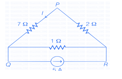
The circuit reduces to a triangular loop.
% The image is commented out so LaTeX won't look for it.
GATE 2024 Electric Circuits Q5 solution figure
The 5A source current splits between two parallel paths:
Path 1 (containing current I): 7\(\Omega\) resistor in series with the 2\(\Omega\) equivalent resistance.
Total \(R_1 = 7+2=9\Omega\).
Path 2: The 1\(\Omega\) equivalent resistance.
By current division rule:
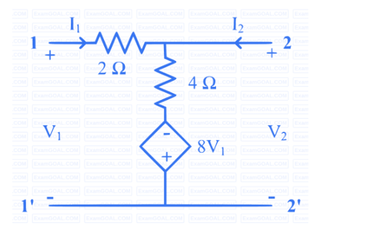
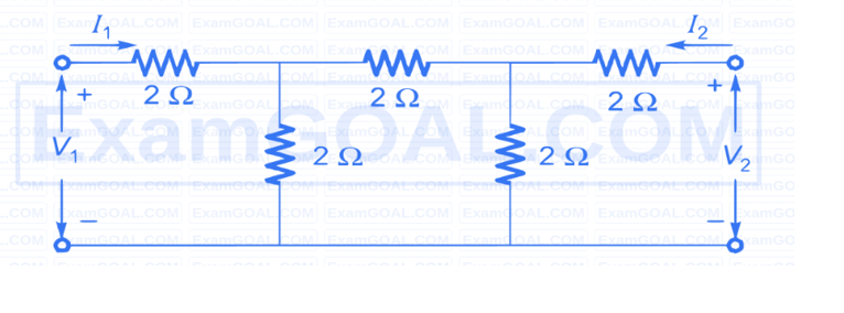
The Z-parameter matrix (with each entry in Ohms) of the network shown below is _____.
Circuit for GATE 2024 Electric Circuits Q6
Solution
The network has a \(\Delta\)-network of 2\(\Omega\) resistors in the center. We convert this to a Y-
network.
Each resistor in the new Y-network \((R_1, R_2, R_3)\) is \(R_Y = \frac{R \times R}{3R} = \frac{2 \times 2}{3 \times 2} = 2/3~\Omega\).
The circuit now becomes a T-network.
The parameters of the equivalent T-network are:
Left arm \(Z_a = 2\Omega + R_1 = 2 + 2/3 = 8/3~\Omega\).
Right arm \(Z_c = 2\Omega + R_2 = 2 + 2/3 = 8/3~\Omega\).
Shunt arm \(Z_b = R_3 = 2/3~\Omega\).
The Z-parameters for this T-network are:
\(Z_{11} = Z_a + Z_b = 8/3 + 2/3 = 10/3~\Omega\).
\(Z_{22} = Z_c + Z_b = 8/3 + 2/3 = 10/3~\Omega\).
\(Z_{12} = Z_{21} = Z_b = 2/3~\Omega\).