A nullator is defined as a circuit element where the voltage across the device and the
current through the device are both zero.
A series combination of a nullator and a
resistor of value, R, will behave as a
resistor of value R
nullator
open circuit
short circuit
Solution
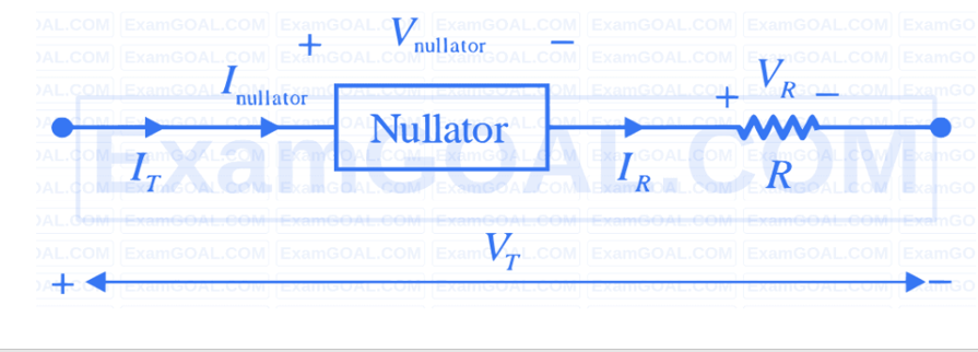
Given: A Nullator is defined as the circuit element where the voltage across the
device and the current through the device both are zero.
\(V_{nullator}=0\) and \(I_{nullator}=0\)
Consider the series combination of a Nullator and a resistor (R):
Let the total current flowing through the series combination be \(I_T\).
Due to the series
connection, \(I_{T}=I_{nullator}=I_{R}\). Since \(I_{nullator}=0\) the total current \(I_T\) must be 0. A circuit
element that permits zero current to flow regardless of the voltage across it is
defined as an open circuit.
GATE 2025 Electric Circuits Q1 solution figure
C
Final Answer
Correct answer: (C) open circuit.
Question 02
Question 2
must come first
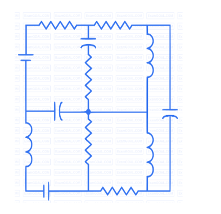
The number of junctions in the circuit is
Circuit for GATE 2025 Electric Circuits Q2
6
7
8
Solution
A junction (or node) is the intersection of 2 or more elements.
Counting all such
intersections in the provided diagram gives 8.
C
Final Answer
Correct answer: (C) 8.
Question 03
Question 3
must come first
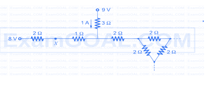
Consider a part of an electrical network as shown below.
Some node voltages, and
the current flowing through the 3\(\Omega\) resistor are as indicated.
The voltage (in Volts)
at node X is _____.
Circuit for GATE 2025 Electric Circuits Q3
Solution
First, find the voltage at node A (the junction between 1\(\Omega\), 3\(\Omega\), 2\(\Omega\)).
The voltage at the top of the 3\(\Omega\) resistor is 9 V. A current of 1 A flows *down* through it.
The voltage
drop across the 3\(\Omega\) resistor is \(V=IR = 1~A \times 3\Omega = 3~V\). The voltage at node A is \(V_A = 9~V - 3~V = 6~V\).
Now, consider the branch from the 8 V source to node A. The total resistance is \(2\Omega + 1\Omega = 3\Omega\). The current \(I_D\) flowing in this branch is:
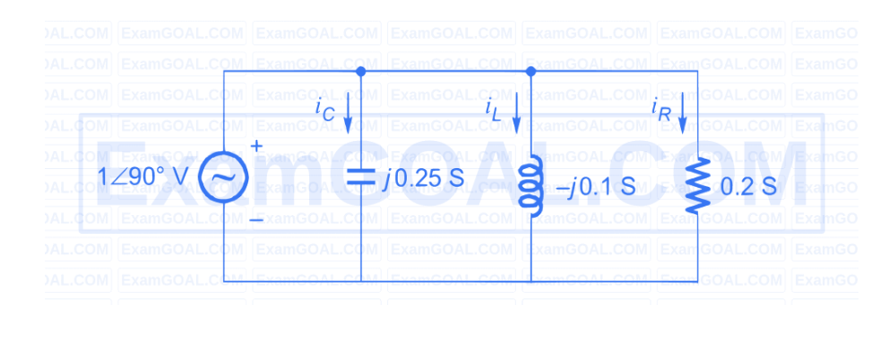
Let \(i_C\), \(i_L\), and \(i_R\) be the currents flowing through the capacitor, inductor, and resistor,
respectively, in the circuit given below.
The AC admittances are given in Siemens(S).
Which one of the following is true?
Circuit for GATE 2025 Electric Circuits Q4
Solution
(Note: Options were not provided, but the solution calculates the currents.)
The voltage source is \(V = 1\angle90^\circ~V\). All elements are in parallel. The admittances are
\(Y_R = 0.2~S\), \(Y_L = -j0.1~S\), and \(Y_C = j0.25~S\). The current in each branch is
\(I = V \times Y\).
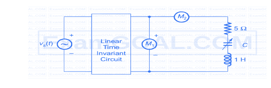
In the circuit below, \(M_1\) is an ideal AC voltmeter and \(M_2\) is an ideal AC ammeter. The
source voltage (in Volts) is \(v_s(t) = 100 \cos(200t)\). What should be the value of the
variable capacitor C such that the RMS readings on M1 and M2 are 25 V and 5 A,
respectively?
Circuit for GATE 2025 Electric Circuits Q5
25\(\mu\)F
4\(\mu\)F
0.25\(\mu\)F
Insufficient information to find C
Solution
The "Linear Time Invariant Circuit" box is a red herring.
The voltmeter \(M_1\) reads 25 V and the ammeter \(M_2\) reads 5 A for the *load* on the right.
The load consists of a 5\(\Omega\) resistor, a capacitor C, and a 1H inductor, all in series.
From the meter readings, we can find the magnitude of the load's impedance Z:
The impedance of the series RLC load is \(Z = R + j(X_L - X_C)\).
Equation
\[|Z| = \sqrt{R^2 + (X_L - X_C)^2} = 5\Omega\]
We are given \(R = 5\Omega\).
Equation
\[\sqrt{5^2 + (X_L - X_C)^2} = 5\]
Equation
\[25 + (X_L - X_C)^2 = 25\]
This implies \((X_L - X_C)^2 = 0\), so \(X_L = X_C\). The circuit is in resonance.
From the source \(v_s(t) = 100 \cos(200t)\), we get \(\omega = 200~rad/s\).