Solved GATE Paper

GATE 2023 Electric Circuits Questions and Solutions

Instructor: Prof. Mithun Mondal Institution: BITS Pilani Subject: Electric Circuits
Question 01

Question 1

In the circuit shown below, the current i flowing through 200\(\Omega\) resistor is ____ mA (rounded off to two decimal places).

GATE 2023 Electric Circuits Q1 circuit diagram
Circuit for GATE 2023 Electric Circuits Q1

Solution

Apply source transformation to the top-right branch (1mA || 1k\(\Omega\)) \(\rightarrow\) 1V source in series with 1k\(\Omega\).

% The image is commented out so LaTeX won't look for it.

GATE 2023 Electric Circuits Q1 circuit diagram
GATE 2023 Electric Circuits Q1 solution figure

Applying nodal analysis at node V (the top center node). (Currents leaving \(= 0\))

Equation
\[\frac{V-2}{2000} + \frac{V}{2000} - 10^{-3} + \frac{V-(-1)}{1000+200} = 0\]
Equation
\[\frac{V-2}{2000} + \frac{V}{2000} - 0.001 + \frac{V+1}{1200} = 0\]

Multiply by 6000:

Equation
\[3(V-2) + 3V - 6 + 5(V+1) = 0\]
Equation
\[3V - 6 + 3V - 6 + 5V + 5 = 0\]
Equation
\[11V - 7 = 0 \Rightarrow V = \frac{7}{11} \approx 0.6363~V\]

The current i (labeled \(i_L\) in solution) through the 200\(\Omega\) resistor is:

Equation
\[i_L = \frac{V+1}{1200} = \frac{0.6363+1}{1200} \approx 1.363 \times 10^{-3} A\]
Equation
\[i_L = 1.36~mA\]
Final Answer
Correct answer: 1.36.
Question 02

Question 2

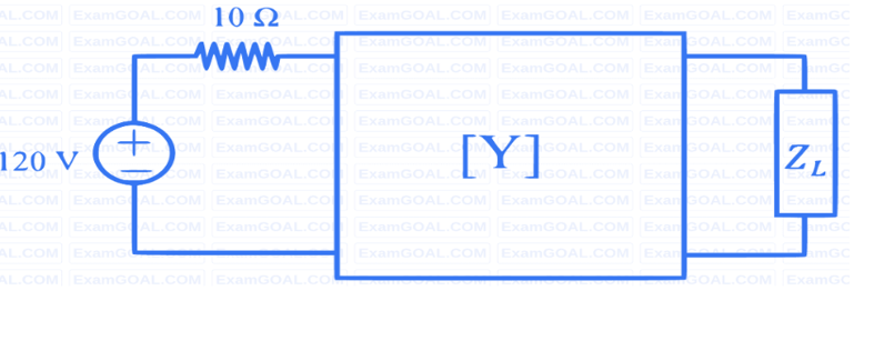
For the two port network shown below, the [Y]-parameters is given as \([Y] = \frac{1}{100} \begin{bmatrix} 2 & -1 \\ -1 & 4/3 \end{bmatrix} S\). The value of load impedance \(Z_L\) in \(\Omega\), for maximum power transfer will be _____ (rounded to the nearest integer).

GATE 2023 Electric Circuits Q2 circuit diagram
Circuit for GATE 2023 Electric Circuits Q2

Solution

For maximum power transfer, \(Z_L = Z_{th}^*\). Since the circuit is resistive, \(Z_L = R_{th}\). \(R_{th}\) is the Thevenin resistance seen by the load \(Z_L\). First, convert the [Y] matrix to its equivalent \(\pi\)-network. \(Y_A = Y_{11} + Y_{12} = (2-1)/100 = 1/100~S \Rightarrow R_A = 100\Omega\). (Shunt at port 1) \(Y_B = Y_{22} + Y_{12} = (4/3-1)/100 = (1/3)/100~S \Rightarrow R_B = 300\Omega\). (Shunt at port 2) \(Y_C = -Y_{12} = 1/100~S \Rightarrow R_C = 100\Omega\). (Series between ports)

The circuit for \(R_{th}\) has the 120V source shorted. We look back from the \(Z_L\) terminals. \(R_{th}\) is \(R_B\) in parallel with (\(R_C\) + (Source resistor \(10\Omega\) || \(R_A\))).

Equation
\[R_{th} = R_B || (R_C + (10\Omega || R_A))\]
Equation
\[R_{th} = 300\Omega || (100\Omega + (10\Omega || 100\Omega))\]
Equation
\[10 || 100 = \frac{10 \times 100}{10 + 100} = \frac{1000}{110} \approx 9.09\Omega\]
Equation
\[R_{th} = 300 || (100 + 9.09) = 300 || 109.09\]
Equation
\[R_{th} = \frac{300 \times 109.09}{300 + 109.09} = \frac{32727}{409.09} \approx 79.99\Omega\]

Rounded to the nearest integer, \(R_{th} = 80\Omega\). Therefore, \(Z_L = 80\Omega\).

Final Answer
Correct answer: 80.
Question 03

Question 3

A series RLC circuit has a quality factor Q of 1000 at a center frequency of \(10^6~rad/s\). The possible values of R, L and C are

  1. \(R=1\Omega\), \(L=1\mu H\) and \(C=1\mu F\)
  2. \(R=0.1\Omega\), \(L=1\mu H\) and \(C=1\mu F\)
  3. \(R=0.01\Omega\), \(L=1\mu H\) and \(C=1\mu F\)
  4. \(R=0.001\Omega\), \(L=1\mu H\) and \(C=1\mu F\)

Solution

We are given \(Q=1000\) and \(\omega_0 = 10^6~rad/s\). All options use \(L=1\mu H\) and \(C=1\mu F\). Let's check the resonant frequency:

Equation
\[\omega_0 = \frac{1}{\sqrt{LC}} = \frac{1}{\sqrt{(10^{-6})(10^{-6})}} = 10^6~rad/s\]

This matches. Now, find R using the Q-factor formula: For a series RLC circuit \(Q = \frac{1}{R}\sqrt{\frac{L}{C}}\).

Equation
\[R = \frac{1}{Q}\sqrt{\frac{L}{C}}\]
Equation
\[R = \frac{1}{1000}\sqrt{\frac{1 \times 10^{-6}~H}{1 \times 10^{-6}~F}} = \frac{1}{1000}\sqrt{1} = 0.001\Omega\]

This matches option (D).

D
Final Answer
Correct answer: (D) \(R=0.001\Omega\), \(L=1\mu H\) and \(C=1\mu F\).
Previous2022
GATE Electric Circuits