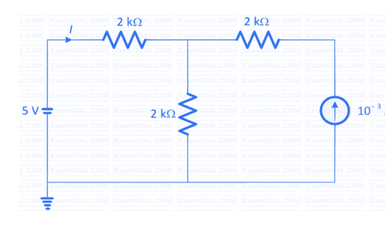
Applying KVL in the single loop, starting from the 5V source:
(This solution assumes the 10mA source is in series with the second 2k\(\Omega\) resistor)
Equation
\[5 = (2~k\Omega) \times I + (2~k\Omega) \times (I + 10^{-3}~A)\]
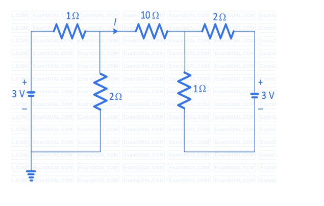
Consider the circuit shown in the figure. The current I flowing through the 10\(\Omega\)
resister is _____.
Circuit for GATE 2022 Electric Circuits Q2
Solution
Let's analyze the right-most loop (Loop-1) containing the 1\(\Omega\) resistor, 2\(\Omega\) resistor,
and 3V source.
Let the current in this loop be \(I_1\).
Apply Kirchhoff's laws in Loop-1:
Equation
\[(2\Omega)I_1 + 3V + (1\Omega)I_1 = 0\]
Equation
\[3I_1 = -3 \Rightarrow I_1 = -1A\]
The current \(I_1 = -1\) A flows only in the right-most loop, independent of the rest of
the circuit.
Since no current can enter or leave this self-contained loop from the
middle branch, the current I must be zero.
✓
Final Answer
Correct answer: 0 A.
Question 03
Question 3
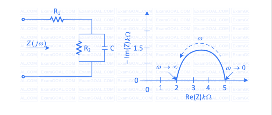
For the circuit shown, the locus of the impedance \(Z(j\omega)\) is plotted as \(\omega\) increases
from zero to infinity.
The values of \(R_1\) and \(R_2\) are:
Circuit for GATE 2022 Electric Circuits Q3
Solution
We analyze the circuit at the two frequency extremes, \(\omega = 0\) and \(\omega = \infty\).
At \(\omega = 0~rad/s\): The capacitor's impedance is \(X_C = \frac{1}{j\omega C} \to \infty\). The capacitor acts as an
open circuit.
The impedance \(Z(0)\) is simply the two resistors in series: \(Z(0) = R_1 + R_2\).
From the graph, at \(\omega \to 0\), \(Z(0) = 5~k\Omega\).
Equation
\[R_1 + R_2 = 5~k\Omega \quad \text{...(1)}\]
At \(\omega = \infty~rad/s\): The capacitor's impedance is \(X_C = \frac{1}{j\omega C} \to 0\). The capacitor acts as
a short circuit, bypassing \(R_2\).
The impedance \(Z(\infty)\) is just \(R_1\): \(Z(\infty) = R_1\).
From the graph, at \(\omega \to \infty\), \(Z(\infty) = 2~k\Omega\).
Equation
\[R_1 = 2~k\Omega\]
Solving: Substitute \(R_1 = 2~k\Omega\) into equation (1):
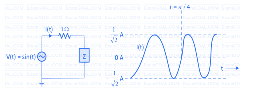
Consider the circuit shown in the figure with input \(V(t)\) in volts.
The sinusoidal
steady state current \(I(t)\) flowing through the circuit is shown graphically (where t
is in seconds).
The circuit element Z can be _____.
Circuit for GATE 2022 Electric Circuits Q4
Solution
From the graphs: \(V(t) = \sin(t) \Rightarrow V_m = 1~V\) and \(\omega = 1~rad/sec\).
\(I(t)\) is a sine wave that
lags \(V(t)\) and has a peak value \(I_m = \frac{1}{\sqrt{2}}~A\).
Since the current lags the voltage, the element Z must have an inductive
reactance.
The total impedance of the circuit is \(Z_0 = R + Z = 1\Omega + jX_L\).
The magnitude of the total impedance is: