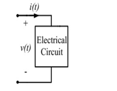
The voltage across the circuit in the figure, and the current through it, are given by:
\(v(t) = 5 - 10\cos(\omega t + 60^\circ)~V\)
\(i(t) = 5 + X \cos(\omega t)~A\)
where \(\omega = 100\pi\) radian/s.
If the average power delivered to the circuit is zero, then the
value of X (in Ampere) is _____ (up to 2 decimal places).
Circuit for GATE 2018 Electric Circuits Q1
Solution
The average power \(P_{avg} = P_{DC} + P_{AC}\).
\(P_{DC} = V_{dc} \times I_{dc} = 5~V \times 5~A = 25~W\).
\(P_{AC} = \frac{1}{2}V_m I_m \cos(\phi)\).
\(v_{ac}(t) = -10\cos(\omega t + 60^\circ) \Rightarrow V_m = -10\).
\(i_{ac}(t) = X \cos(\omega t) \Rightarrow I_m = X\). The phase difference is \(60^\circ\).
Total average power is zero: \(P_{avg} = 25 - 2.5X = 0\).
Equation
\[2.5X = 25 \Rightarrow X = 10~A\]
✓
Final Answer
Correct answer: 10.
Question 02
Question 2
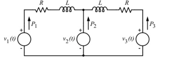
In the figure, the voltages are \(v_1(t) = 100\cos(\omega t)\), \(v_2(t) = 100\cos(\omega t + \pi/18)\) and \(v_3(t) = 100\cos(\omega t + \pi/36)\).
The circuit is in sinusoidal steady state, and \(R \ll \omega L\). \(P_1, P_2\) and
\(P_3\) are the average power outputs.
Which one of the following statements is true?
Circuit for GATE 2018 Electric Circuits Q2
\(P_1 = P_2 = P_3 = 0\)
\(P_1 < 0, P_2 > 0, P_3 < 0\)
\(P_1 < 0, P_3 > 0, P_2 < 0\)
\(P_1 > 0, P_2 < 0, P_3 > 0\)
Solution
% The image is commented out so LaTeX won't look for it.
%
GATE 2018 Electric Circuits Q2 solution figure
Let's find the phase angles:
\(V_1\) phase = \(0^\circ\).
\(V_2\) phase = \(\pi/18\) rad = \(10^\circ\).
\(V_3\) phase = \(\pi/36\) rad = \(5^\circ\).
The source with the most leading phase angle will deliver power (\(P > 0\)), while the
others will absorb power (\(P < 0\)).
Here, \(V_2\) has the most leading phase (\(10^\circ\)). Therefore, \(V_2\) is the source delivering power (\(P_2 > 0\)).
\(V_1\) and \(V_3\) are absorbing power (\(P_1 < 0\) and \(P_3 < 0\)).
For the circuit shown in the figure, the Thevenin voltage and resistance looking
into X-Y are
Circuit for GATE 2018 Electric Circuits Q3
\(\frac{4}{3}V\), 2\(\Omega\)
4V, \(2/3\) \(\Omega\)
4/3 V, \(2/3\Omega\)
4V, 2\(\Omega\)
Solution
\(V_{th} = V_{oc}\): Apply nodal analysis at node \(V_x\) (which is \(V_{oc}\)).
Let \(i\) be current down through the middle 1\(\Omega\). \(V_x = i \times 1 = i\).
KCL at \(V_x\): \(\frac{V_x}{2} - 2 + V_x + \frac{V_x - 2i}{1} = 0\).
Substitute \(i = V_x\):
\(\frac{V_x}{2} - 2 + V_x + V_x - 2V_x = 0 \Rightarrow 0.5V_x - 2 = 0 \Rightarrow V_x = 4~V\).
\(V_{th} = V_{oc} = 4V\).
\(R_{th}\): Find \(I_{sc}\) (short circuit X to Y).
When shorted, \(V_x = 0\), so \(i = V_x / 1\Omega = 0\).
The dependent source \(2i = 0\) (a short circuit).
The 2\(\Omega\) resistor is shorted out. The 2A source current flows through the short.
\(I_{sc} = 2~A\).
\(R_{th} = V_{oc} / I_{sc} = 4~V / 2~A = 2\Omega\).
D
Final Answer
Correct answer: (D) 4V, 2\(\Omega\).
Question 04
Question 4
The RC circuit shown in the figure is
Circuit for GATE 2018 Electric Circuits Q4
A low-pass filter
A high-pass filter
A band-pass filter
A band-reject filter
Solution
We analyze the transfer function \(H(j\omega) = V_o / V_i\) at frequency extremes.
At \(\omega = 0\) (DC): Capacitors are open circuits. The series capacitor blocks the signal, so \(V_o = 0\). \(H(0) = 0\).
At \(\omega = \infty\) (high freq): Capacitors are short circuits. The shunt capacitor shorts the output to ground, so \(V_o = 0\). \(H(\infty) = 0\).
At \(\omega = 1/RC\) (a mid-frequency): The gain is non-zero.
Since the gain is zero at low and high frequencies and non-zero in between, it is a band-pass filter.