Solved GATE Paper

GATE 2016 Electric Circuits Questions and Solutions

Instructor: Prof. Mithun Mondal Institution: BITS Pilani Subject: Electric Circuits
Question 01

Question 1

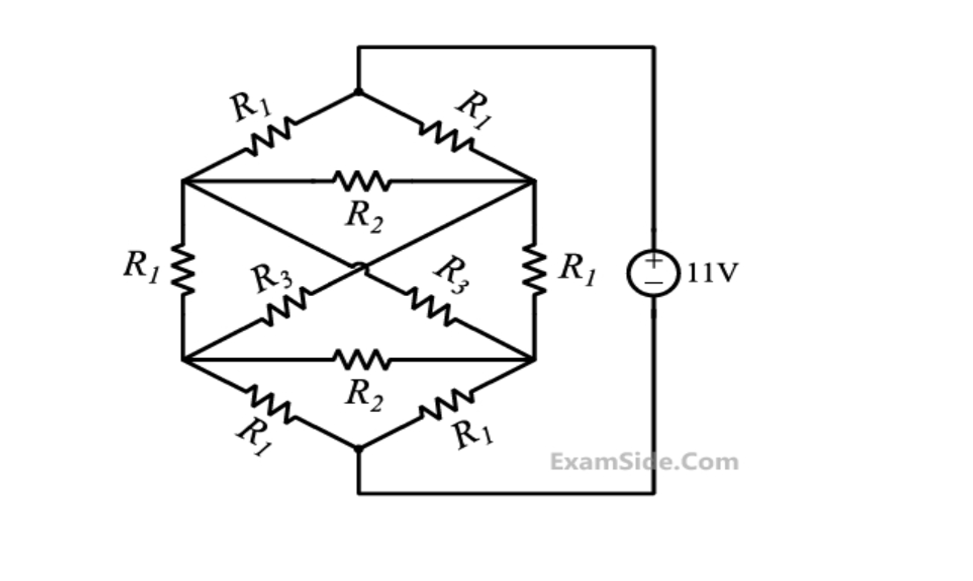
Consider the network shown below with \(R_1=1\Omega\), \(R_2=2\Omega\) and \(R_3=3\Omega\). The network is connected to a constant voltage source of 11 V. The magnitude of the current (in amperes) delivered by the voltage source is _____.

GATE 2016 Electric Circuits Q1 circuit diagram
Circuit for GATE 2016 Electric Circuits Q1

Solution

Find equivalent resistance \(R_{eq}\). (Following the solution's formula):

Equation
\[R_{eq} = R_1 + \frac{R_1 R_3}{2(R_1 + R_3)} = 1 + \frac{1 \times 3}{2(1 + 3)} = 1 + \frac{3}{8} = \frac{11}{8}\Omega\]
Equation
\[I_s = \frac{V_s}{R_{eq}} = \frac{11V}{11/8\Omega} = 8~A\]
Final Answer
Correct answer: 8 A.
Question 02

Question 2

In the circuit shown in the figure, the magnitude of the current (in amperes) through \(R_2\) is _____.

GATE 2016 Electric Circuits Q2 circuit diagram
Circuit for GATE 2016 Electric Circuits Q2

Solution

Nodal analysis at node \(v_A\).

Equation
\[\frac{v_A - 60}{5} - 0.04v_x + \frac{v_A}{3+5} = 0\]

The voltage \(v_x\) is across \(R_3\). Using voltage divider:

Equation
\[v_x = v_A \times \frac{5}{3+5} = \frac{5}{8} v_A\]

Substitute \(v_x\) into the nodal equation:

Equation
\[\frac{v_A - 60}{5} - 0.04\left(\frac{5}{8}v_A\right) + \frac{v_A}{8} = 0\]
Equation
\[0.2v_A - 12 - 0.025v_A + 0.125v_A = 0 \Rightarrow 0.3v_A = 12 \Rightarrow v_A = 40~V\]

Current through \(R_2 = \frac{v_A}{R_2 + R_3} = \frac{40}{3 + 5} = 5~A\).

Final Answer
Correct answer: 5 A.
Question 03

Question 3

In the figure shown, the current i (in ampere) is _____.

GATE 2016 Electric Circuits Q3 circuit diagram
Circuit for GATE 2016 Electric Circuits Q3

Solution

Nodal analysis at center node \(V_1\):

Equation
\[\frac{V_1}{1} + \frac{V_1 - 8}{1} + \frac{V_1}{1} + \frac{V_1 - 8}{1} = 0 \Rightarrow 4V_1 = 16 \Rightarrow V_1 = 4~V\]

Using KCL from solution: \(i = V_1 - 5 = 4 - 5 = -1A\).

Final Answer
Correct answer: -1 A.
Question 04

Question 4

In the circuit shown, the Norton equivalent resistance (in \(\Omega\)) across terminals a-b is _____.

GATE 2016 Electric Circuits Q4 circuit diagram
Circuit for GATE 2016 Electric Circuits Q4

Solution

Apply \(V_{dc}\) at a-b, find \(I_{dc}\). KCL at node a (Vdc), using \(4I = V_{dc}\) (since \(I = V_{dc}/4\)):

Equation
\[\frac{V_{dc} - 4I}{2} + \frac{V_{dc}}{2} + \frac{V_{dc}}{4} - I_{dc} = 0\]
Equation
\[\frac{V_{dc} - V_{dc}}{2} + \frac{V_{dc}}{2} + \frac{V_{dc}}{4} = I_{dc} \Rightarrow \frac{3V_{dc}}{4} = I_{dc}\]
Equation
\[R_N = R_{TH} = \frac{V_{dc}}{I_{dc}} = \frac{4}{3}\Omega \approx 1.33\Omega\]
Final Answer
Correct answer: 1.33 \(\Omega\).
Question 05

Question 5

In the circuit shown in the figure, the maximum power (in watt) delivered to the resistor R is _____.

GATE 2016 Electric Circuits Q5 circuit diagram
Circuit for GATE 2016 Electric Circuits Q5

Solution

\(P_{max} = V_{TH}^2 / (4R_{TH})\). Find \(v_g\) from the left circuit using voltage divider:

Equation
\[v_g = 5 \times (2 / (3 + 2)) = 2~V\]

Find \(V_{TH}\) for the right circuit (open-circuit voltage across R):

Equation
\[V_{TH} = (100 v_g) \times (40 / (10 + 40)) = (100 \times 2) \times (40 / 50) = 160~V\]

Find \(R_{TH}\) (looking into R terminals, \(v_g\) depends on source, but source is independent and deactivated, so \(v_g=0\), dependent source is 0V \(\to\) short):

Equation
\[R_{TH} = 10~k\Omega || 40~k\Omega = (10 \times 40) / (10 + 40) = 8~k\Omega = 8000\Omega\]
Equation
\[P_{max} = \frac{(160)^{2}}{4 \times 8000} = \frac{25600}{32000} = 0.8~W\]
Final Answer
Correct answer: 0.8 W.
Question 06

Question 6

Consider a two-port network with the transmission matrix: \(T = \begin{bmatrix} A & B \\ C & D \end{bmatrix}\). If the network is reciprocal, then

  1. \(T^{-1} = T\)
  2. \(T^2 = T\)
  3. Determinant(T) = 0
  4. Determinant(T) = 1

Solution

For reciprocity, \(AD - BC = 1\), which is the determinant of the T matrix.

D
Final Answer
Correct answer: (D) Determinant(T) = 1.
Question 07

Question 7

An independent voltage source in series with an impedance \(Z_S = R_S + jX_S\) delivers a maximum average power to a load impedance \(Z_L\) when

  1. \(Z_L = R_S + jX_S\)
  2. \(Z_L = R_S\)
  3. \(Z_L = jX_S\)
  4. \(Z_L = R_S - jX_S\)

Solution

The Maximum Power Transfer Theorem states that for maximum average power transfer... the load impedance must be the complex conjugate of the source impedance: \(Z_L = Z_S^*\). If \(Z_S = R_S + jX_S\) then \(Z_L = R_S - jX_S\).

D
Final Answer
Correct answer: (D) \(Z_L = R_S - jX_S\).
Question 08

Question 8

In the AC network shown in the figure, the phasor voltage \(V_{AB}\) (in Volts) is (No image provided in PDF for this question)

  1. 0
  2. \(5\angle 30^\circ\)
  3. \(12.5\angle 30^\circ\)
  4. \(17\angle 30^\circ\)

Solution

(Based on the solution) The voltage \(V_{AB}\) is across a parallel combination, driven by a current source \(I = 5\angle 30^\circ~A\). Impedance of left branch \(Z_1 = 5 - j3~\Omega\). Impedance of right branch \(Z_2 = 5 + j3~\Omega\). Equivalent impedance \(Z_{eq} = Z_1 || Z_2 = \frac{(5 - j3)(5 + j3)}{(5 - j3) + (5 + j3)} = \frac{25 + 9}{10} = 3.4\Omega\). Voltage \(V_{AB} = I \times Z_{eq} = (5\angle 30^\circ) \times 3.4 = 17\angle 30^\circ~V\).

D
Final Answer
Correct answer: (D) \(17\angle 30^\circ\).
Question 09

Question 9

An AC source of RMS voltage 20V with internal impedance \(Z_s = (1 + 2j)\Omega\) feeds a load of impedance \(Z_L = (7 + 4j)\Omega\). The reactive power consumed by the load is

  1. 8 VAR
  2. 16 VAR
  3. 28 VAR
  4. 32 VAR

Solution

Total impedance \(Z_{total} = Z_s + Z_L = (1 + 2j) + (7 + 4j) = 8 + 6j~\Omega\). Magnitude of RMS current \(|I_{rms}| = \frac{|V_{rms}|}{|Z_{total}|} = \frac{20}{|8 + 6j|} = \frac{20}{\sqrt{8^2 + 6^2}} = \frac{20}{10} = 2A\). Reactive power consumed by the load \(Q_L = |I_{rms}|^2 \times X_L\), where \(X_L\) is the reactive part of \(Z_L\). \(X_L = 4\Omega\). \(Q_L = (2)^2 \times 4 = 16 \text{ VAR}\).

B
Final Answer
Correct answer: (B) 16 VAR.
Previous2015
GATE Electric Circuits