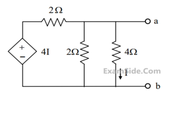
In the circuit shown in the figure , the Norton equivalent resistance (in \(\Omega\)) across terminals a-b is:
(This was a numerical answer type question in the source, but calculating \(R_N\) is the main task.)
Circuit for GATE 2015 Electric Circuits Q1
Solution
Method: Since the circuit contains a dependent source (\(4I\)), we find the Norton Resistance \(R_N\) (which equals \(R_{Th}\)) using the test voltage method: \(R_N = V_{test} / I_{test}\).
Apply Test Source: Apply a test voltage \(V_{\text{test}} = V_{ab}\) across terminals a-b. This voltage appears across the \(2\,\Omega\) and \(4\,\Omega\) parallel resistors.
Relate Dependent Source: The dependent voltage source is \(4I\). The current \(I\) is shown flowing down through the \(4\,\Omega\) resistor, so \(I = V_{ab} / 4\). Thus, the dependent source value is \(4I = 4(V_{ab}/4) = V_{ab}\).
KCL at Node \(a\) (\(V_{ab}\)): Apply KCL (sum of currents leaving \(= 0\), where \(I_{test}\) is the current leaving the test source):
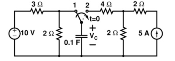
The switch in the circuit shown in the figure has been in position 1 for a long time and abruptly changes to position 2 at \(t=0\). If time \(t\) is in seconds, the capacitor voltage \(V_c\) (in volts) for \(t>0\) is given by:
Circuit for GATE 2015 Electric Circuits Q2
\(4(1-e^{-t/0.5})\)
\(10-6e^{-t/0.5}\)
\(4(1-e^{-t/0.6})\)
\(10-6e^{-t/0.6}\)
Solution
Initial Voltage (\(V_c(0^-)\)): With the switch at position 1, the circuit is DC. The capacitor acts as an open circuit. \(V_c(0^-)\) is the voltage across the \(2\,\Omega\) resistor (due to voltage division).
Since capacitor voltage cannot change instantaneously, \(V_c(0^+) = V_c(0^-) = 4\,\text{V}\).
Final Voltage (\(V_c(\infty)\)): For \(t>0\), the switch is at position 2. The circuit stabilizes, and the capacitor acts as an open circuit. The final voltage \(V_c(\infty)\) is the voltage across the capacitor, which is the voltage across the parallel \(2\,\Omega\) resistor, found by source transformation or inspection. Since the \(2\,\Omega\) resistor is in parallel with the \(5\,A\) source, \(V_{c}(\infty) = 5\,\text{A} \times 2\,\Omega = 10\,\text{V}\).
Time Constant (\(\tau\)): For \(t>0\), the source on the left is disconnected. The equivalent resistance seen by the capacitor is \(R_{eq} = 4\,\Omega + 2\,\Omega = 6\,\Omega\).
Equation
\[\tau = R_{eq} C = 6\,\Omega \times 0.1\,F = 0.6\,\text{s}\]
Transient Equation: The capacitor voltage for \(t>0\) is:
The condition for maximum power transfer to a load impedance \(Z_L = R_L + jX_L\) from a source with internal impedance \(Z_S = R_S + jX_S\) is:
\(R_L = R_S\) and \(X_L = X_S\)
\(R_L = R_S\) and \(X_L = -X_S\)
\(R_L = |Z_S|\) and \(X_L = 0\)
\(Z_L = R_S\)
Solution
For a complex source impedance, maximum power is transferred when the load impedance is the conjugate of the source impedance, i.e., \(Z_L = Z_S^*\).
B
Final Answer
Correct answer: (2) \(R_L = R_S\) and \(X_L = -X_S\).
Question 04
Question 4
A two-port network is reciprocal if its admittance parameters satisfy which of the following conditions?
\(y_{11} = y_{22}\)
\(y_{12} = -y_{21}\)
\(y_{12} = y_{21}\)
\(y_{11}y_{22} - y_{12}y_{21} = 1\)
Solution
A two-port network is considered reciprocal if the ratio of the output current (Port 2) to the input voltage (Port 1) equals the ratio of the input current (Port 1) to the output voltage (Port 2) under appropriate open/short circuit conditions. In terms of the Y-parameters (Admittance parameters), this condition is \(y_{12} = y_{21}\).
The condition \(y_{11} = y_{22}\) indicates a symmetric network.