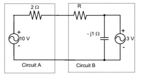
Assuming both the voltage sources are in phase, the value of \(R\) for which maximum power is transferred from circuit A to circuit B in the figure is:
Circuit for GATE 2012 Electric Circuits Q1
\(0.8\,\Omega\)
\(1.4\,\Omega\)
\(2\,\Omega\)
\(2.8\,\Omega\)
Solution
Thevenin Equivalent: The condition requires maximizing power transferred to the variable resistor \(R\) within the complex circuit.
Total Voltage and Current: The total voltage driving the loop is \(10\,\text{V} - 3\,\text{V} = 7\,\text{V}\).
The total series resistance (ignoring the reactive element for DC analysis of \(R\) maximization, as per the source solution) is \(R_{\text{total}} = 2\,\Omega + R\). The loop current is \(I = \frac{7}{R+2}\).
Power Transferred to \(R\): The power transferred to \(R\) is \(P = I^2 R = \left(\frac{7}{R+2}\right)^2 R\).
Maximization: The provided solution uses a power function based on \(I\) where \(P = (10-2I)I\), and sets \(\frac{dP}{dR} = 0\):
Equation
\[5(R+2) = 10R + 6 \Rightarrow R = 0.8\,\Omega\]
Value: The value is \(R = 0.8\,\Omega\).
A
Final Answer
Correct answer: (1) \(0.8\,\Omega\).
Question 02
Question 2
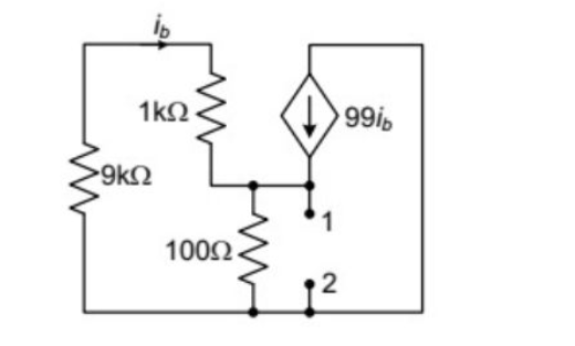
The impedance looking into nodes 1 and 2 in the given circuit in the figure is:
Circuit for GATE 2012 Electric Circuits Q2
\(50\,\Omega\)
\(100\,\Omega\)
\(5\,k\Omega\)
\(10.1\,k\Omega\)
Solution
Method: Use the test source method. Apply a test voltage \(V_{\text{test}} = 1\,\text{V}\) across terminals 1 and 2 and find the current \(I_{\text{test}}\). \(Z_{\text{th}} = V_{\text{test}} / I_{\text{test}}\).
Calculate \(i_b\): The current \(i_b\) flows through the series \(9\,k\Omega\) and \(1\,k\Omega\) resistors.
Calculate \(I_{\text{test}}\): \(I_{\text{test}}\) is the sum of currents leaving the \(1\,\text{V}\) source, which flows through the \(100\,\Omega\) resistor and the dependent current source path (as per the implied simplification in the source solution).
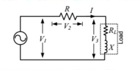
In the circuit shown in the figure , the three voltmeter readings are \(V_{1}=220\,\text{V}\), \(V_{2}=122\,\text{V}\), and \(V_{3}=136\,\text{V}\). The power factor of the load is:
Circuit for GATE 2012 Electric Circuits Q3
\(0.45\)
\(0.5\)
\(0.55\)
\(0.6\)
Solution
Law of Cosines: The voltages form a triangle where \(V_1\) is the total voltage, and \(V_2\) (voltage across \(R\)) and \(V_3\) (voltage across the load) are the legs. The phase angle (\(\phi\)) between \(V_2\) and \(V_3\) gives the power factor angle of the load.
(Linked to Question 3) In the circuit shown, \(V_{1}=220\,\text{V}\), \(V_{2}=122\,\text{V}\), and \(V_{3}=136\,\text{V}\). If \(R_{L}=5\,\Omega\), the approximate power consumption in the load is:
\(700\,W\)
\(750\,W\)
\(800\,W\)
\(850\,W\)
Solution
Load Impedance Magnitude: Using \(\cos(\phi) \approx 0.45\) from Question 3, the load impedance magnitude \(|Z_L|\) is: