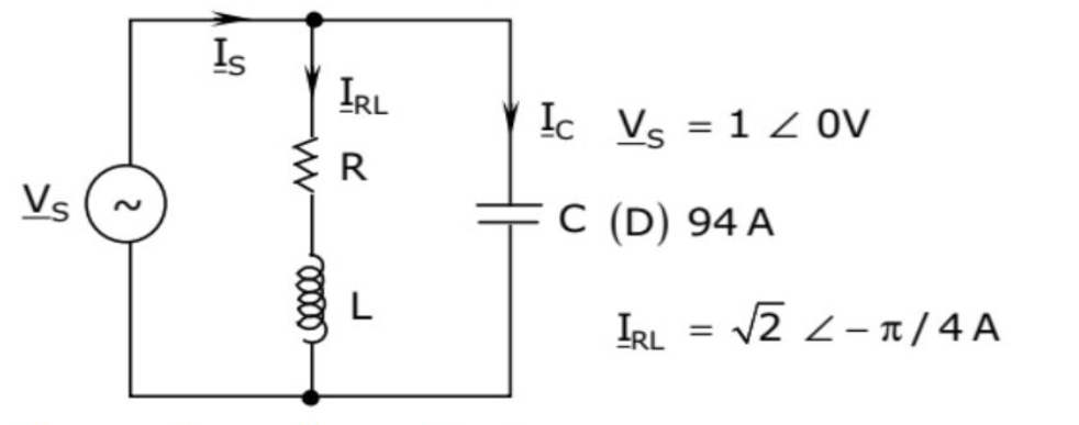
An RLC circuit with relevant data is given in the figure . The power dissipated in the resistor \(R\) is: (\(V_S = 1\angle 0^\circ V\) and \(I_{RL} = \sqrt{2}\angle -\pi/4 A\) are given.)
Circuit for GATE 2011 Electric Circuits Q1
\(0.5\,W\)
\(1\,W\)
\(\sqrt{2}\,W\)
\(2\,W\)
Solution
Method: The power dissipated in the resistor \(R\) is \(P_R = |I_{RL, rms}|^2 R\). Alternatively, the solution uses the total power \(P_S\) assuming the inductor and capacitor are lossless.
Power Calculation (from source's method): The power supplied by the source \(P_S\) is calculated using the total source current magnitude \(|I_S|\) and the phase difference \(\phi\):
(Assuming \(|I_S| = |I_{RL}| = \sqrt{2}\,A\) and the phase angle of the total current is \(\pi/4\) for the power calculation.)
B
Final Answer
Correct answer: (2) \(1\,W\).
Question 02
Question 2
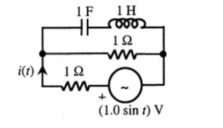
The r.m.s value of the current \(i(t)\) in the circuit shown in the figure is:
Circuit for GATE 2011 Electric Circuits Q2
\(\frac{1}{2}\,A\)
\(\frac{1}{\sqrt{2}}\,A\)
\(1\,A\)
\(2\,A\)
Solution
Source and Frequency: The source voltage is \(V_S(t) = 1.0 \sin(t)\,V\), which gives a peak voltage \(V_m = 1\,V\) and angular frequency \(\omega = 1\,rad/s\).
Impedance Calculation: The parallel LC branch impedance (\(Z_{LC}\)) is:
Total Impedance: Since the parallel LC branch is a short circuit (\(Z_{LC}=0\)), the total impedance seen by the voltage source is only the series resistor (\(1\,\Omega\)).
Note: the L–C section is in series and reaches resonance at \(\omega=1\,\mathrm{rad/s}\), so its net reactance is zero and it behaves as a short; the total impedance is the \(1\,\Omega\) resistor alone.
B
Final Answer
Correct answer: (2) \(\frac{1}{\sqrt{2}}\,A\).
Question 03
Question 3
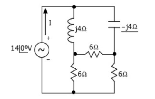
In the circuit shown in the figure , the current \(I\) is equal to:
Circuit for GATE 2011 Electric Circuits Q3
\(14\angle 0^\circ\,A\)
\(2.0\angle 0^\circ\,A\)
\(2.8\angle 0^\circ\,A\)
\(3.2\angle 0^\circ\,A\)
Solution
Method: The three \(6\,\Omega\) resistors form a Delta (\(\Delta\)) network. Convert this to an equivalent Wye (Y) network using \(\Delta\)-Y transformation.
Y-Resistor Value: Since all resistors in the \(\Delta\) are equal (\(R_\Delta = 6\,\Omega\)), the equivalent Y-resistor value is \(R_Y = \frac{R_\Delta \times R_\Delta}{3 R_\Delta} = \frac{6 \times 6}{3 \times 6} = 2\,\Omega\).
Simplified Circuit: The circuit simplifies to a series impedance \(Z_{series} = 2\,\Omega\) followed by a parallel combination: \(Z_{parallel} = (R_Y + j4\,\Omega) || (R_Y - j4\,\Omega)\).