By the end of this chapter you should be able to:
Describe the open-delta connection and when it is used.
Derive its capacity as \(\sqrt3\) times one unit's rating, and explain why the answer is not two thirds.
Distinguish the 57.74 % and 86.6 % ratios and say what each compares.
Compute the power factors at which the two transformers operate.
Size an open-delta pair for a stated load.
Explain why vector groups are necessary.
Read the clock notation and identify the common groups.
Apply the paralleling rules and estimate the circulating current when they are broken.
The Open-Delta Connection
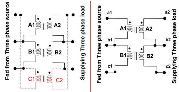
Remove one transformer from a Δ-Δ bank and the remaining two still deliver three-phase power. The connection that results is called open delta or V-V.
It can be used when one of the transformers in a Δ-Δ bank is disabled, and the service is to be continued until the faulty transformer is repaired or replaced.
It can also be used for small three-phase loads where the installation of a full three-transformer bank is unnecessary.
The total load-carrying capacity is 57.7 % of what it would be for the delta-delta connection.
Two transformers give two line voltages, say \(V_{AB}\) and \(V_{BC}\). The third follows from Kirchhoff's voltage law round the open triangle:
The missing side of the delta is supplied by the other two, and a balanced three-phase set of line voltages appears exactly as before. Nothing is lost in voltage — the loss is entirely in current capability.
Why the Capacity Is \(\sqrt3\) Times One Unit
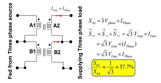
The whole result turns on one change: what current each transformer carries.
Each winding carries the phase current, which is \(1/\sqrt3\) of the line current:
With the third leg gone there is nothing to share with, so each winding carries the full line current:
Removing one transformer of three costs 42.3 % of the capacity, not 33.3 %, because the two survivors must each carry \(\sqrt3\) times the current they carried before, and their windings are not rated for it.
Problem. The Δ-Δ bank of three 500 kVA units from Chapter 52 loses one transformer. Find the open-delta capacity, the capacity lost, and the loading of each survivor.
Closed-bank capacity.
Open-delta capacity.
As a fraction of the original.
Loading of each survivor.
Comment. Note the two different percentages, which are easy to confuse. 57.74 % compares the open bank with the original three-transformer bank; 86.60 % compares it with the two transformers that remain. Both are correct answers to different questions.
The second figure is the more surprising. Two perfectly healthy 500 kVA transformers, 1000 kVA of plant, can deliver only 866 kVA — they cannot even be fully loaded. Section 53-4 explains why.
The Utilisation Factor
| Ratio | Value | Compares | Name |
|---|---|---|---|
| \(\dfrac{\sqrt3S}{3S}\) | 0.5774 | Open delta with the original bank | Capacity ratio |
| \(\dfrac{\sqrt3S}{2S}\) | 0.8660 | Open delta with the two remaining units | Utilisation factor |
Problem. A student argues that since two of three transformers remain, the capacity should be 66.7 %. Show where the argument fails.
The naive figure.
The actual figure.
Where the argument fails. It assumes each surviving transformer keeps carrying what it carried before. It does not — the winding current changes:
So for the same line current, each survivor now carries \(\sqrt3\) times as much:
Comment. The error is to count transformers when the binding constraint is winding current. Two thirds of the transformers remain, but each must do \(\sqrt3\) times the current work it did before, and that is what caps the line current.
A useful check on the direction of the error: the true answer must be less than two thirds, since the survivors are being asked to work harder per unit of output. The factor \(1/\sqrt3 = 0.577\) is indeed below \(0.667\).
The Two Power Factors
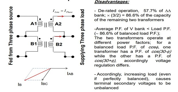
In a closed delta all three transformers work at the load power factor. In an open delta they do not, because the phasor geometry displaces each transformer's voltage from its current by an extra \(\pm30^{\circ}\).
Adding, and using \(\cos(A+B) + \cos(A-B) = 2\cos A\cos B\):
The total is the correct three-phase power, but it is split unequally between the two machines — and the split depends on the load power factor.
Problem. Tabulate the power factors and outputs of the two transformers at load power factors of 1.0, 0.866, 0.8 and 0.5 lagging. Take \(V_LI_L = 1\).
| Load pf | \(\phi\) | pf of T1 | pf of T2 | \(P_1\) | \(P_2\) | Total |
|---|---|---|---|---|---|---|
| 1.000 | 0.00° | 0.8660 | 0.8660 | 0.8660 | 0.8660 | 1.7321 |
| 0.866 | 30.00° | 0.5000 | 1.0000 | 0.5000 | 1.0000 | 1.5000 |
| 0.800 | 36.87° | 0.3928 | 0.9928 | 0.3928 | 0.9928 | 1.3856 |
| 0.500 | 60.00° | 0.0000 | 0.8660 | 0.0000 | 0.8660 | 0.8660 |
Sample working, unity power factor (\(\phi = 0\)):
And at 0.5 lagging (\(\phi = 60^{\circ}\)):
Comment. At unity power factor both transformers work at 0.866, and there is the utilisation factor: even under the most favourable conditions neither machine can exceed 86.6 % of its rating.
At 0.5 lagging the result is striking. One transformer delivers no real power at all — it carries current and voltage, and dissipates copper loss, but its voltage and current are in quadrature. The whole of the load's real power comes from the other machine.
This is why open delta is a temporary expedient rather than a design choice for heavy inductive loads. It also explains a practical observation: the two transformers of an open-delta pair heat unequally, and which one runs hotter depends on the load power factor.
Applications and Limitations
Emergency continuity after one unit of a Δ-Δ bank fails.
Small three-phase loads where a full bank is unnecessary — two transformers cost less than three.
Anticipated growth: install two now and add the third later, converting to full Δ-Δ without disturbing the existing pair.
Rural distribution where the load is mostly single-phase with a small three-phase motor.
Only 57.7 % of the closed-bank capacity.
Utilisation limited to 86.6 % of the two units' rating.
The two transformers work at different power factors and heat unequally.
Secondary voltages become unbalanced as load increases, because the two transformers have unequal internal drops.
Greater voltage regulation than the closed bank.
The voltage-unbalance point is worth noting. In a closed delta the three secondary voltages are held by the delta itself; in an open delta the third voltage is only the sum of the other two, so any inequality in the two internal impedance drops appears directly as unbalance.
Problem. A 150 kVA three-phase load is to be supplied by two transformers in open delta. Find the rating required, and compare the total transformer kVA with that of a closed Δ-Δ bank.
Rating of each unit.
Choosing standard 100 kVA units.
Comparison with a closed bank, which would need three 50 kVA units:
Comment. Open delta needs 15.5 % more transformer kVA to serve the same load, but only two units instead of three. Fewer units means fewer bushings, fewer connections, less installation labour and a smaller footprint, which is why it can be the cheaper choice despite the poorer utilisation.
With standard sizes the arithmetic worsens: 200 kVA of plant for a 150 kVA load, or 33.3 % more. The penalty is real but the count of units usually decides it.
Note the loading figure of 86.60 % — the utilisation factor again, arriving here as the answer to a sizing question rather than as an abstract ratio.
Why Vector Groups Are Needed
Chapter 52 showed that a mixed connection introduces a \(30^{\circ}\) shift between primary and secondary line quantities, and Chapter 49 listed matching phase displacement as the fourth condition for parallel operation. A notation is needed to record it.
Two secondaries of equal magnitude \(V\) separated by an angle \(\theta\) leave a difference voltage round the loop:
For \(\theta = 30^{\circ}\) this is \(2\sin15^{\circ} = 0.5176\) per unit — more than half the rated voltage, driven through only the two transformers' impedances.
The magnitudes may match perfectly and the impedances may be identical; if the phase displacement differs, the banks must not be connected. This is why the displacement is stamped on every three-phase transformer's nameplate.
The Clock Notation
The designation has three parts, read left to right.
| Part | Meaning | In Dyn11 |
|---|---|---|
| Capital letter | HV winding connection: D delta, Y star, Z zigzag | D — HV in delta |
| Small letter | LV winding connection: d, y, z | y — LV in star |
| n or N | Neutral brought out (small for LV, capital for HV) | n — LV neutral available |
| Number | Clock hour: LV lags HV by that many \(\times30^{\circ}\) | 11 — lags 330°, i.e. leads 30° |
Picture a clock face. The HV phasor always points to twelve. The LV phasor points to the hour given by the number, and each hour is \(30^{\circ}\) of lag.
Only even-numbered groups are possible for Yy and Dd; only odd for Yd and Dy — because a mixed connection necessarily brings in the \(30^{\circ}\).
Hour 11 is the common one for step-down units, since a lag of \(330^{\circ}\) is a lead of \(30^{\circ}\), and it is often convenient for the LV to lead.
The Common Groups
| Group | Connection | Shift | Typical use |
|---|---|---|---|
| Yy0 | Star – star | 0° | Small HV units, usually with a tertiary delta |
| Dd0 | Delta – delta | 0° | Large LV units; can run open delta |
| Dyn11 | Delta – star, LV neutral | 330° (lead 30°) | The standard distribution transformer |
| Yd1 | Star – delta | 30° lag | Step-down at a transmission substation |
| Yd11 | Star – delta | 330° | Step-down where a 30° lead is wanted |
| YNd11 | Star – delta, HV neutral | 330° | Grid transformers with an earthed HV neutral |
| Dzn0 | Delta – zigzag | 0° | Where earth-fault current must be supplied |
Paralleling Rules
Two three-phase transformers may be paralleled only if their clock numbers are identical — in addition to Chapter 49's conditions on ratio, polarity and percentage impedance.
Yy0 may parallel with Dd0; Dyn11 with Yd11; but never a group ending in an odd number with one ending in an even number.
Two useful exceptions exist in practice. Some pairs differing by \(180^{\circ}\) — such as Yd1 and Yd7 — can be reconciled by relabelling the phases, since interchanging two terminals reverses the sense. And a Dy11 unit can be made to match a Dy1 unit by reversing the phase sequence of its connections. Both are done at the design stage, not on site.
Before paralleling, the nameplate groups are compared and a phasing check is made with a voltmeter across each pair of open switch contacts. All three readings should be zero.
A non-zero reading means a group, polarity or phase-sequence mismatch, and the switch must not be closed. The voltmeter costs nothing; closing onto a 30° mismatch destroys both transformers.
Problem. Decide whether each pair may be paralleled, and estimate the circulating current for the mismatched ones, taking a combined impedance of 0.10 pu.
| Pair | Displacement | Verdict | \(\Delta V\) | Circulating current |
|---|---|---|---|---|
| Dyn11 & Dyn11 | 0° | Permitted | 0 | 0 |
| Yy0 & Dd0 | 0° | Permitted | 0 | 0 |
| Yd1 & Yy0 | 30° | Not permitted | 0.5176 pu | 5.18 pu |
| Dyn11 & Yd1 | 60° | Not permitted | 1.0000 pu | 10.0 pu |
| Yy0 & Yy6 | 180° | Not permitted | 2.0000 pu | 20.0 pu |
Working, the Dyn11 and Yd1 pair. Clock numbers 11 and 1 differ by 10 hours:
Comment. Even the mildest mismatch, \(30^{\circ}\), drives five times rated current continuously — well beyond anything the windings can survive, and comparable with a short circuit.
The 180° case is the worst at twenty times rated, since the two secondaries are then in direct opposition and the full difference of \(2V\) appears across the loop. This is the same failure as reversed polarity in Chapter 49, arrived at by a different route.
Note that Yy0 and Dd0 pair happily despite having different connections. What must match is the phase displacement, not the winding arrangement — which is exactly why the clock number, and not the letters, is the operative part of the designation.
Summary and Key Formulas
Open delta uses two transformers to deliver three-phase power; the third line voltage follows from \(V_{CA} = -(V_{AB} + V_{BC})\).
In a closed delta each winding carries \(I_L/\sqrt3\); in an open delta it carries the full line current, which is what caps the capacity.
\(S_{open} = \sqrt3\,S_{unit}\), so the bank gives \(1/\sqrt3 = 57.74\,\%\) of the closed Δ-Δ capacity — not two thirds.
The utilisation factor \(\sqrt3/2 = 86.60\,\%\) compares the output with the two remaining units' combined rating.
The two transformers work at \(\cos(30^{\circ}\pm\phi)\), so they heat unequally. At unity pf both run at 0.866; at 0.5 lagging one delivers no power at all.
Open delta needs \(2/\sqrt3 = 15.47\,\%\) more transformer kVA than a closed bank, but only two units.
Vector groups record the phase displacement: capital letter for HV, small for LV, n or N for a neutral, and a clock number giving the LV lag in units of 30°.
Yy and Dd give even numbers; Yd and Dy give odd. Dyn11 is the standard distribution transformer.
Two banks may be paralleled only if the clock numbers match. A difference voltage \(2V\sin(\theta/2)\) otherwise drives a large circulating current — five times rated at only 30°.
| Quantity | Formula | Notes |
|---|---|---|
| Closed-delta bank | \(S_{\Delta\Delta} = 3S_{unit}\) | each winding at \(I_L/\sqrt3\) |
| Open-delta bank | \(S_{open} = \sqrt3\,S_{unit}\) | each winding at \(I_L\) |
| Capacity ratio | \(1/\sqrt3 = 0.5774\) | vs the original bank |
| Utilisation factor | \(\sqrt3/2 = 0.8660\) | vs the two survivors |
| Output of each unit | \(P_{1,2} = V_LI_L\cos(30^{\circ}\pm\phi)\) | unequal duty |
| Their sum | \(\sqrt3\,V_LI_L\cos\phi\) | correct 3-phase power |
| Extra plant needed | \(2/\sqrt3 = 1.1547\) | 15.47 % more |
| Phase displacement | \(\theta = n\times30^{\circ}\) | \(n\) = clock number |
| Difference voltage | \(\Delta V = 2V\sin(\theta/2)\) | 0.5176 pu at 30° |
| Circulating current | \(I_{circ} = \Delta V/Z_{p.u.}\) | 5.18 pu at 30° |
Common Mistakes
Saying open delta gives two thirds of the capacity. It gives \(1/\sqrt3 = 57.74\,\%\), because the binding constraint is winding current, not the number of transformers.
Confusing 57.74 % with 86.60 %. The first compares with the original three-unit bank, the second with the two units that remain.
Assuming the two transformers share equally. They work at \(\cos(30^{\circ}\pm\phi)\) and heat unequally.
Expecting either machine to reach full rating. Even at unity power factor neither exceeds 86.6 %.
Thinking the open delta loses a line voltage. All three remain; only current capability is lost.
Reading the clock number as leading. It is the lag of the LV behind the HV.
Matching letters instead of numbers. Yy0 and Dd0 may be paralleled although their connections differ.
Expecting an odd group to parallel with an even one. Mixed and like connections can never agree.
Treating a 30° mismatch as minor. It drives about five times rated current.
Skipping the voltmeter phasing check because the nameplates appear to match.
Chapter Review
For open-delta problems decide first which quantity is capped — it is always the winding current. For vector groups, convert both designations to degrees before comparing.
P53.1 A Δ-Δ bank of three 200 kVA transformers loses one unit. Find the open-delta capacity and the percentage of the original.
Show answer
\[S_{open} = \sqrt3\,(200) = 346.41~\mathrm{kVA}\]\[\frac{346.41}{600} = 57.74\,\%, \qquad \text{lost} = 253.59~\mathrm{kVA}\]P53.2 For P53.1, find the loading of each surviving transformer.
Show answer
Neither can be fully loaded, however light the demand elsewhere.\[\frac{346.41}{(2)(200)} = \frac{346.41}{400} = 86.60\,\%\]P53.3 Two transformers in open delta supply a load at 0.8 lagging. Find the power factor at which each operates.
Show answer
\[\phi = \cos^{-1}(0.8) = 36.87^{\circ}\]\[\text{pf}_1 = \cos\left(30^{\circ} + 36.87^{\circ}\right) = \cos66.87^{\circ} = 0.3928\]Very unequal — the second transformer does most of the real work.\[\text{pf}_2 = \cos\left(30^{\circ} - 36.87^{\circ}\right) = \cos\left(-6.87^{\circ}\right) = 0.9928\]P53.4 A 90 kVA three-phase load is to be supplied in open delta. Find the minimum rating of each transformer.
Show answer
\[S_{unit} = \frac{90}{\sqrt3} = 51.96~\mathrm{kVA} \quad\Longrightarrow\quad \text{choose 60 kVA units}\]\[\text{capacity} = \sqrt3\,(60) = 103.92~\mathrm{kVA}, \qquad \text{loading} = \frac{90}{103.92} = 86.60\,\%\]P53.5 Two banks are Yd11 and Dy11. May they be paralleled?
Show answer
Yes. Both have clock number 11, so both displace the LV by 330°. The connections differ, but what must match is the phase displacement, not the winding arrangement — provided the ratios, polarities and percentage impedances also agree.P53.6 A Dyn11 bank is inadvertently paralleled with a Yd1 bank of the same rating, the combined impedance being 0.08 pu. Estimate the circulating current.
Show answer
\[\left|11 - 1\right|\times30^{\circ} = 300^{\circ} \equiv 60^{\circ}\]\[\Delta V = 2\sin30^{\circ} = 1.0000~\mathrm{pu}\]Both transformers would be destroyed unless protection operated within a cycle or two.\[I_{circ} = \frac{1.0000}{0.08} = 12.5~\mathrm{pu} = 1250\,\%\ \text{of rated}\]P53.7 Derive the capacity of the open-delta connection and explain why it is not two thirds of the closed bank.
Show answer
Closed delta. Each winding carries the phase current \(I_{ph} = I_L/\sqrt3\), so one unit is ratedand the bank delivers \(\sqrt3V_LI_L = 3S_{unit}\).\[S_{unit} = V_{ph}I_{ph} = \frac{V_LI_L}{\sqrt3}\]Open delta. With the third leg removed there is no parallel path, so each winding carries the full line current, \(I_{ph} = I_L\). To stay within rating,
\[I_L \le \frac{S_{unit}}{V_L} \quad\Longrightarrow\quad S_{open} = \sqrt3V_LI_L = \sqrt3\,S_{unit}\]\[\frac{S_{open}}{S_{\Delta\Delta}} = \frac{\sqrt3S_{unit}}{3S_{unit}} = \frac{1}{\sqrt3} = 0.5774\]Why not two thirds. That figure counts transformers, but the binding constraint is winding current. Each survivor must carry \(\sqrt3\) times the current it carried in the closed bank, so the line current must be reduced by \(1/\sqrt3\) to keep within rating. Two thirds of the machines remain, but each is worked \(\sqrt3\) times harder per ampere of line current.
P53.8 Show that the two transformers of an open delta operate at different power factors, and find the load power factor at which one delivers no power.
Show answer
The phasor geometry displaces each transformer's voltage from the line current by an extra \(\pm30^{\circ}\), soTheir sum recovers the correct three-phase power:\[P_1 = V_LI_L\cos\left(30^{\circ} + \phi\right), \qquad P_2 = V_LI_L\cos\left(30^{\circ} - \phi\right)\]\[P_1 + P_2 = 2V_LI_L\cos30^{\circ}\cos\phi = \sqrt3\,V_LI_L\cos\phi\]Zero output occurs when \(30^{\circ} + \phi = 90^{\circ}\), that is \(\phi = 60^{\circ}\), a load power factor of 0.5 lagging. At that point \(P_1 = 0\) while \(P_2 = V_LI_L\cos30^{\circ}\) carries the whole load.
The first transformer still carries current and voltage, and still dissipates copper loss — its voltage and current are simply in quadrature. At unity power factor both run at 0.866, which is the utilisation factor, so neither machine ever reaches its full rating.
P53.9 Explain the clock notation and why odd and even groups cannot be paralleled.
Show answer
The designation gives the HV connection as a capital letter (D, Y, Z), the LV as a small letter, an n or N where a neutral is brought out, and a clock number giving the phase displacement:The HV phasor is imagined at twelve o'clock and the LV phasor at the stated hour. Thus Dyn11 is HV delta, LV star with neutral, LV lagging by 330° — equivalently leading by 30°.\[\theta = (\text{clock number})\times30^{\circ}\ \text{lagging}\]Odd versus even. Like connections (Yy, Dd) introduce no inherent shift, so their displacement is a multiple of 60° and the clock number is even. Mixed connections (Yd, Dy) necessarily bring in the 30° of the star-delta transformation, so their number is odd.
An odd and an even group therefore differ by an odd multiple of 30°, which can never be zero. Paralleling them leaves a difference voltage \(2V\sin(\theta/2)\) round the loop — 0.5176 pu at 30° — driving several times rated current through the two transformers' impedances alone.
P53.10 Why is Dyn11 the standard distribution transformer connection?
Show answer
Because one connection answers three separate requirements at once.The HV delta gives the third-harmonic magnetising current a closed path in which to circulate, so the flux stays sinusoidal and no harmonic voltages are induced — the problem that spoils the Yy connection.
The LV star provides a four-wire supply, so that single-phase loads at the phase voltage and three-phase loads at the line voltage can be served from the same transformer.
The brought-out neutral gives a solid earth reference for protection and for consumer safety.
The delta is on the HV side where the current is small, so the conductor saving matters less than the harmonic path it provides; and the star is on the LV side where the neutral is needed.
The 11 rather than 1 is convention: a 330° lag is a 30° lead, and standardising on it means that distribution transformers across a network share one group and can be paralleled freely.
MCQ 1. The open-delta capacity as a fraction of the closed Δ-Δ bank is:
(a) 2/3 (b) \(1/\sqrt3\) (c) \(\sqrt3/2\) (d) 1/2Show answer
(b) \(1/\sqrt3\) = 57.74 %.MCQ 2. The utilisation factor of the two remaining transformers is:
(a) 0.5774 (b) 0.6667 (c) 0.8660 (d) 1.0000Show answer
(c) 0.8660 = \(\sqrt3/2\).MCQ 3. In an open delta, each transformer winding carries:
(a) \(I_L/\sqrt3\) (b) the full line current (c) \(\sqrt3I_L\) (d) half the line currentShow answer
(b) the full line current, which is what caps the capacity.MCQ 4. At unity power factor, each open-delta transformer works at a power factor of:
(a) 1.000 (b) 0.866 (c) 0.707 (d) 0.500Show answer
(b) 0.866 — \(\cos30^{\circ}\), for both machines.MCQ 5. One open-delta transformer delivers zero power when the load power factor is:
(a) 1.0 (b) 0.866 (c) 0.707 (d) 0.5 laggingShow answer
(d) 0.5 lagging, where \(30^{\circ} + \phi = 90^{\circ}\).MCQ 6. In Dyn11, the letter n indicates:
(a) a neutral brought out on the LV side (b) a neutral on the HV side (c) no neutral (d) a zigzag windingShow answer
(a) a neutral brought out on the LV side — small letter for LV.MCQ 7. The clock number gives the phase displacement in units of:
(a) 15° (b) 30° (c) 45° (d) 60°Show answer
(b) 30°, the LV lagging the HV.MCQ 8. Which pair may be paralleled?
(a) Yy0 and Dd0 (b) Yd1 and Yy0 (c) Dyn11 and Yd1 (d) Yy0 and Yy6Show answer
(a) Yy0 and Dd0 — both have zero displacement, though their connections differ.MCQ 9. A 30° group mismatch with a combined impedance of 0.10 pu gives a circulating current of about:
(a) 0.5 pu (b) 1.0 pu (c) 5.2 pu (d) 20 puShow answer
(c) 5.2 pu, since \(2\sin15^{\circ} = 0.5176\) divided by 0.10.MCQ 10. Compared with a closed bank serving the same load, open delta needs how much more transformer kVA?
(a) none (b) 15.5 % (c) 33.3 % (d) 73.2 %Show answer
(b) 15.5 %, since \(2/\sqrt3 = 1.1547\).
Describe the open-delta connection and explain why three line voltages remain available.
Derive the open-delta capacity and explain why it is not two thirds of the closed bank.
Distinguish the capacity ratio from the utilisation factor.
Show that the two transformers operate at different power factors, and find where one delivers no power.
Give the applications and limitations of the connection.
Explain why vector groups are necessary and what a mismatch costs.
Explain the clock notation and the rule about odd and even numbers.
State the paralleling rules and describe the practical phasing check.
Two chapters of Part 3 remain after the next. Chapter 54 develops the harmonic behaviour that Chapters 52 and 53 have repeatedly invoked but never derived — why the third harmonic is peculiar to three-phase working, why it is in phase in all three lines rather than 120° apart, and how the choice of connection and of earthing decides whether the flux or the current bears the distortion. The tertiary winding, mentioned as a remedy since Chapter 52, is treated properly there.
Chapter 55 takes up the Scott connection, which converts three phases to two using a main transformer with a centre tap and a teaser at the 0.866 point — the same \(\sqrt3/2\) that appeared here as the utilisation factor, arriving from a quite different direction. Chapter 56 then closes Part 3 with instrument transformers, the current and potential transformers on which all measurement and protection depend, before Part 4 opens on induction motors.