Demonstrative Video
Consider three 1-\(\Phi\) identical transformer each rating of \(10 KVA, 200V/ 100V, 50 Hz\)
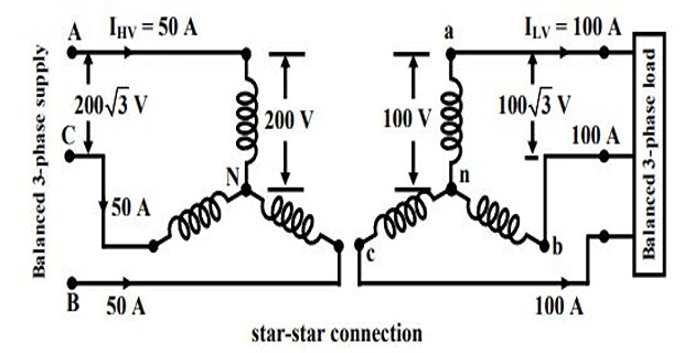
Total KVA that can be supplied to the load: \(\sqrt{3}V_LI_L = \sqrt{3} (\sqrt{3}100) = 30 KVA\)
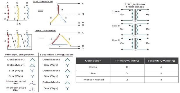
Generally used for small, high-voltage transformers. Because of star connection, number of required turns/phase is reduced (as \(V_p=1/\sqrt{3}V_L\)). Thus, the amount of insulation required is also reduced.
This connection can be used only if the connected load is balanced
Problems Associated With Star-Star Connection
The Y-Y connection has two very serious problems. They are
Not satisfactory for the unbalance load in the absence of a neutral connection. If the neutral is not provided, then the phase voltages become severely unbalance when the load is unbalanced.
The Y-Y connection contains a third harmonics, and in balanced conditions, these harmonics are equal in magnitude and phase with the magnetising current. Their sum at the neutral of star connection is not zero, and hence it will distort the flux wave which will produce a voltage having a harmonics in each of the transformers
The unbalanced and third harmonics problems of Y-Y connection can be solved by using the solid ground of neutral and by providing tertiary windings.
Total KVA that can be supplied to the load: \(\sqrt{3}V_LI_L = \sqrt{3}100(\sqrt{3}100) = 30KVA\)
This connection is mainly used in step down transformer at the substation end of the transmission line
The main use of this connection is at the substation end of the transmission line where the voltage is to be stepped down
This can be used to provide 3-pase 4-wire service (Y-with neutral grounded)
The ratio between secondary to primary line voltage is \(1/\sqrt{3}\) times the transformation ratio of each transformer
There is a \(30^\circ\) shift between the primary and secondary line voltage which means that a \(Y-\Delta\) transformer bank cannot be paralleled with either a \(Y-Y\) or \(\Delta-\Delta\) bank
Also third harmonic currents flows in the \(\Delta\) to provide a sinusoidal flux
Used to step-up the voltage as for example, at the beginning of high tension transmission system
3-phase 4 wire service (Y-neutral grounded)
Connection gained popularity because it can serve both the 3-phase power equipment and single-phase lightning circuits
Because of \(30^\circ\) shift between primary and secondary line voltages and line currents, it is impossible to parallel such a bank with a \(\Delta-\Delta\) or \(Y-Y\) bank
The ratio of primary voltage is \(\sqrt{3}\) times the transformation ratio of each transformer
This connection is generally used for large, low-voltage transformers. Number of required phase/turns is relatively greater than that for Y-Y connection
This connection can be used even for unbalanced loading
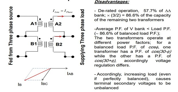
Another advantage of this type of connection is that even if one transformer is disabled, system can continue to operated in open delta connection but with reduced available capacity
This connection can be used when one of the transformers in \(\Delta-\Delta\) bank is disabled and the service is to be continued until the faulty transformer is repaired or replaced.
It can also be used for small three phase loads where installation of full three transformer bank is unnecessary
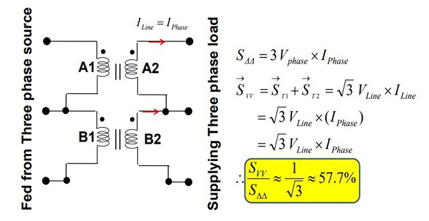
The total load carrying capacity of open-delta connection is 57.7% than that would be for delta-delta connection
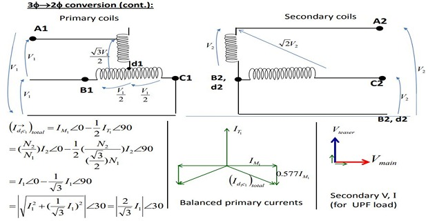
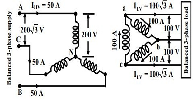
3-phase to 2-phase and vice versa
Proposed by Charles F. Scott
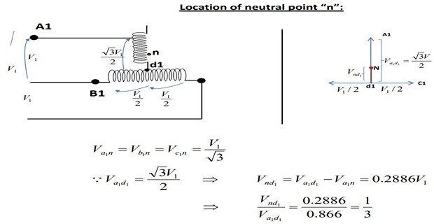
Main Transformer: Centre taps both on primary and secondary winding forms the horizontal member
Teaser Transformer: 0.866 tap. Its one end of the primary and secondary winding is joined to the centre taps on both primary and secondary of the main transformer, respectively.
The other end \(A_1\) of the teaser primary and the two ends \(B_1\) and \(C_1\) of the main transformer primary are connected to the 3-phase supply

Electric furnace installation where it is desired to operate two single-phase together and draw the balanced load from the three-phase supply.
Supply the single phase loads such as electric train which are so scheduled as to keep the load on the three phase system as nearly as possible.
Link a 3-phase system with a two–phase system with the flow of power in either direction.
The Scott-T connection permits conversions of a 3-phase system to a 2-phase system and vice versa. But since 2-phase generators are not available, the converters from two phases to three phases are not used in practice.

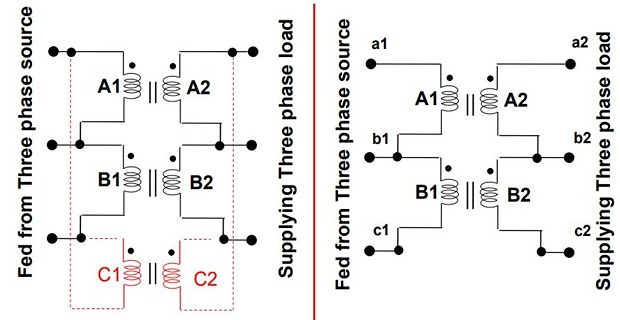
The two Transformers are connected electrically but not magnetically

Assume a 3-phase \(V_L = 100~V\) and \(K = 1\)

Scott Explain \(E_{DC}\) and \(E_{DB}\) differ by \(180^\circ\) because both coils are on the same magnetic circuit and are connected in opposition
Each side of the equilateral triangle represents 100 V
Voltage \(E_{DA}\) is \((\sqrt{3}/2)\times 100=86.6~V\) and lags behind the voltage across the main by \(90^\circ\)
The same relation holds good in the secondary winding so that \(abc\) is a symmetrical 3-phase system
With reference to secondary voltage triangle for UPF load \(I_{db}\) lags \(E_{db}\) by \(30^\circ\) and \(I_{dc}\) leads \(E_{dc}\) by \(30^\circ\)
In other words, the teaser and each half of the main transformer, all operates at different power factors
Obviously, the full rating of the transformers is not being utilized
The teaser transformer operates at only 0.866 of its rated voltage
The main transformer coils operate at \(\cos 30^\circ = 0.866\) power factor, which is equivalent to the main transformers coils working at 86.6% of their KVA rating
Hence, the capacity to rating ratio in a T-T connection is 86.6%–the same as in V-V connection if two identical units are used

Scott Explain2