By the end of this chapter you should be able to:
Distinguish dynamically from statically induced EMF and identify which occurs in a given device.
Derive \(e = Blv\) and \(e = Blv\sin\theta\) from the area swept by a moving conductor.
Derive the EMF of a rotating coil as \(e = 2NBlv\sin\theta\) and show it agrees with \(E = 4.44 f N\Phi_m\).
Subdivide statically induced EMF into self-induced and mutually induced, and state the defining relation for each.
Apply \(e = L\,\mathrm{d}I/\mathrm{d}t\) and \(e_m = M\,\mathrm{d}I_1/\mathrm{d}t\) to practical problems.
Reconcile the inductance form with the flux form of Faraday's law for the same coil.
Explain why an induction motor exhibits both mechanisms, and compute rotor EMF and frequency at a given slip.
Recognise that both types are the same law — only the reason the flux linkage changes differs.
Introduction
Chapters 10 and 11 established Faraday's law and its direction. This chapter classifies the results. Faraday's law says that an EMF appears whenever the flux linkage of a circuit changes, but it says nothing about why it changes — and the two possible reasons lead to two families of machine that look nothing alike.
If the conductor moves through a steady field, the EMF is dynamically induced, and the device is a generator. If the conductor stays put while the flux varies in time, the EMF is statically induced, and the device is a transformer. The classification is not merely tidy bookkeeping: it determines whether the machine needs a prime mover or an AC supply, whether it has a rotor, and which of the two derivations in this chapter you should reach for.
Statically induced EMF splits further, according to whether the varying flux is produced by the coil's own current or by a neighbour's. That gives self-induced and mutually induced EMF, and with them the two quantities — inductance \(L\) and mutual inductance \(M\) — that Chapters 13 and 14 develop in full.
The Two Ways of Changing Flux Linkage
When flux linking with a conductor (or coil) changes, an EMF is induced in it. This change in flux linkages can be obtained in the following two ways.
- By either moving the conductor and keeping the magnetic field system stationary, or moving the magnetic field system and keeping the conductor stationary, in such a way that the conductor cuts across the magnetic field — as in the case of DC and AC generators. The EMF induced in this way is called dynamically induced EMF.
- By changing the flux linking with the coil (or conductor) without moving either the coil or the field system. The change of flux produced by the field system linking with the coil is obtained by changing the current in the field system (solenoid), as in transformers. The EMF induced in this way is called statically induced EMF.
Dynamically Induced EMF
By either moving the conductor keeping the magnetic field system stationary, or moving the field system keeping the conductor stationary, so that flux is cut by the conductor, the EMF thus induced in the conductor is called dynamically induced EMF.

Let a conductor of length \(l\) move a small distance \(\mathrm{d}x\) in time \(\mathrm{d}t\), perpendicular to a uniform field \(B\).
Now suppose the conductor is moved at an angle \(\theta\) with the direction of the magnetic field, at a velocity \(v\) metres per second.
A small distance covered by the conductor in that direction is \(\mathrm{d}x\) in time \(\mathrm{d}t\) seconds.
Then the component of distance perpendicular to the magnetic field, which produces the EMF, is \(\mathrm{d}x\sin\theta\).
Problem. A conductor 0.35 m long moves at 15 m/s in a uniform field of 0.85 T. Find the induced EMF when the motion is (a) perpendicular to the field, (b) at 60° to the field, and (c) along the field.
(a) Perpendicular, \(\theta = 90^{\circ}\):
(b) At 60°:
(c) Along the field, \(\theta = 0\):
Comment. Case (c) is the one worth remembering. The conductor is moving at 15 m/s through a strong field and generating precisely nothing, because it sweeps no new flux — it merely slides along the lines it is already linking. Cutting flux, not moving through a field, is what induces an EMF.
EMF in a Rotating Coil
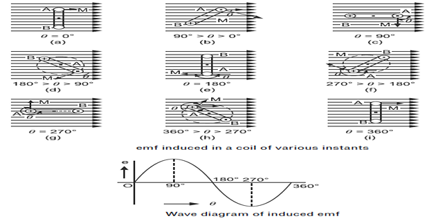
The most important case of dynamically induced EMF is a coil rotating in a magnetic field — the elementary generator. Consider a rotor rotating in the clockwise direction at a constant angular velocity \(\omega\) radians per second.
The velocity component perpendicular to the field is \(v_p = v\sin\theta\).
The EMF induced in one conductor is therefore \(e = Blv\sin\theta\).
As the coil has two conductors — the two sides of the loop, whose EMFs add because they move in opposite directions through opposite field polarities — \(e = 2Blv\sin\theta\).
If the coil has \(N\) turns, \(e = 2NBlv\sin\theta\).
where \(\theta\) is measured from the field direction and \(\alpha = 90^{\circ} - \theta\) from the perpendicular to it — the two forms are identical, and different textbooks use different references. The peak occurs when the coil plane lies along the field, where the conductors move directly across the lines.
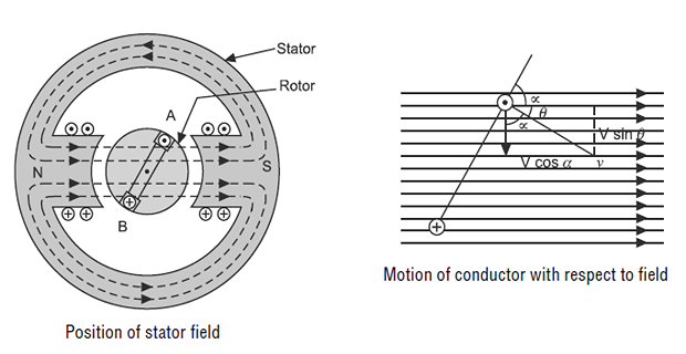
The formula \(e = 2NBlv\sin\theta\) looks quite unlike the \(E = 4.44 f N\Phi_m\) of Chapter 8. They are the same result. For a coil of radial dimension \(r\) and axial length \(l\), the enclosed area is \(A = 2rl\) and the peripheral speed is \(v = \omega r\), so
which on dividing by \(\sqrt{2}\) gives \(E = 4.44 f N\Phi_m\) exactly. The "cutting flux" picture and the "rate of change of flux linkage" picture are two descriptions of one phenomenon — and Worked Example 12.2 verifies the equality numerically.
Problem. A coil of 150 turns rotates at 1200 rev/min in a uniform field of 0.7 T. Each conductor is 0.25 m long and the coil radius is 0.12 m. Find the peak EMF by the conductor formula, and verify it against the flux-linkage formula. Then find the RMS value.
Route 1 — the conductor formula.
Route 2 — the flux-linkage formula.
RMS value.
Check against the EMF equation: \(4.44 f N \Phi_m = (4.44)(20)(150)(0.042) = 559.4\) V \(\checkmark\) (the small difference is the rounding of 4.443 to 4.44).
Comment. Three routes, one answer. Whenever a generator problem gives dimensions rather than flux, use the conductor formula; when it gives flux, use the EMF equation — but be reassured that they can never disagree, since one is derived from the other.
Statically Induced EMF
When the coil and magnetic field system are both stationary but the magnetic field linking with the coil changes — by changing the current producing the field — the EMF thus induced in the coil is called statically induced EMF.
Nothing moves. There is no \(v\), so \(e = Blv\) is of no use whatever, and Faraday's law must be applied in its original form \(e = -N\,\mathrm{d}\Phi/\mathrm{d}t\). This is the transformer case, and it requires an alternating supply for exactly the reason Chapter 8 gave: with DC the flux is steady and nothing is induced.
Statically induced EMF is of two kinds:
Self-induced EMF
Mutually induced EMF
The distinction is simply whose current is changing — the coil's own, or a neighbour's.
Self-Induced EMF
The EMF induced in a coil due to the change of its own flux linked with it is called self-induced EMF.

The magnitude of the self-induced EMF is directly proportional to the rate of change of current in the coil:
The constant of proportionality \(L\) is the self-inductance or simply the inductance of the coil, measured in henries. One henry is the inductance of a coil in which a current changing at one ampere per second induces one volt.
Reconciling with Faraday's law. The two forms describe the same EMF. Since the flux is produced by the coil's own current, \(\lambda = N\Phi = LI\), and differentiating gives
so \(L = N\Phi/I = \lambda/I\). Chapter 13 develops this into \(L = N^{2}/S = N^{2}P\), the result hinted at in Chapter 2.
Problem. A coil of 800 turns has an inductance of 0.4 H. The current through it falls uniformly from 6 A to 1 A in 0.02 s. Find the self-induced EMF by both routes, and the flux at each current.
Route 1 — the inductance form.
Flux linkages and flux. Since \(\lambda = LI = N\Phi\):
Route 2 — Faraday's law directly.
Comment. The two routes must agree, because \(L\) is defined so that they do. Use whichever data the problem supplies. Note also the polarity: the current is falling, so by Lenz's law the induced EMF acts to maintain it — the coil tries to keep the current flowing, which is precisely what produces the arc when an inductive circuit is opened.
Mutually Induced EMF
The EMF induced in a coil due to the change of flux produced by another (neighbouring) coil linking with it is called mutually induced EMF.

Since the rate of change of flux linking with coil B depends upon the rate of change of current in coil A, the magnitude of the mutually induced EMF is directly proportional to the rate of change of current in coil A:
The constant \(M\) is the mutual inductance between the two coils, also measured in henries. One henry of mutual inductance induces one volt in the second coil when the first coil's current changes at one ampere per second.
Equivalently, in terms of the flux actually linking the second coil,
where \(\Phi_2\) is the part of coil A's flux that links coil B. Only a fraction of A's flux reaches B in general, and Chapter 14 quantifies that fraction as the coefficient of coupling \(k\), with \(M = k\sqrt{L_1L_2}\).
Problem. Two coils have a mutual inductance of 0.15 H. The current in coil A is reduced uniformly from 10 A to 2 A in 0.05 s. Coil B has 500 turns. Find the EMF induced in coil B and the change in flux linking it.
Induced EMF.
Change in flux linkage of coil B.
Change in flux.
Check. Applying Faraday's law directly to coil B,
Comment. Coil B has no electrical connection to coil A whatever, yet 24 V appears across it. That complete electrical isolation combined with energy transfer is the single most useful property in electrical engineering — it is why the mains supply in a building can be safely derived from an 11 kV distributor, and why Part 3 of this book is devoted to the device that exploits it.
Where Each Type Occurs
| Feature | Dynamically induced | Statically induced |
|---|---|---|
| What moves | Conductor or field system | Nothing |
| Why the linkage changes | Flux is cut | Flux varies in time |
| Working formula | \(e = Blv\sin\theta\) | \(e = L\dfrac{\mathrm{d}I}{\mathrm{d}t}\) or \(M\dfrac{\mathrm{d}I_1}{\mathrm{d}t}\) |
| Supply needed | DC or AC field; a prime mover | AC only |
| Typical device | DC and AC generators | Transformers, inductors |
| Energy source | Mechanical | Electrical |
| Subdivisions | — | Self-induced, mutually induced |
At standstill, the rotor is stationary while the stator's rotating field sweeps past it. The rotor conductors cut flux at the full supply frequency — the machine behaves as a transformer with a short-circuited secondary, and the EMF is statically induced from the stator's point of view.
Once running, the rotor chases the field and only the slip speed remains. The rotor EMF and frequency both fall in proportion to the slip:
Chapter 60 develops this properly. It is the clearest illustration in the book that the two mechanisms are not different physics but different circumstances.
Problem. A four-pole, three-phase induction motor is supplied at 50 Hz. Its standstill rotor EMF is 120 V per phase. Find the synchronous speed, and the rotor EMF and frequency when running at 1440 rev/min.
Synchronous speed.
Slip.
Rotor EMF and frequency.
Comment. At standstill the rotor sees the full 120 V at 50 Hz; running normally it sees 4.8 V at 2 Hz. Both figures follow from the same principle — the EMF depends on relative motion, and running has almost eliminated it.
Two consequences of practical importance follow. First, the enormous standstill EMF is why an induction motor draws five to seven times full-load current at switch-on, and why the starters of Chapter 66 exist. Second, the very low running frequency of 2 Hz means rotor core loss is negligible — the result anticipated in Chapter 6.
Applications
Pure dynamically induced EMF. The conductor formula \(e = 2NBlv\) is the starting point of every armature-winding calculation in Chapters 23 and 73.
Pure mutually induced EMF, with the coupling maximised by a common iron core. Part 3 develops the entire theory from \(e_m = M\,\mathrm{d}I_1/\mathrm{d}t\).
Self-induced EMF used deliberately to oppose current change — smoothing rectifier output, limiting fault current, and stabilising arcs in welding sets.
Interrupting a large \(\mathrm{d}I/\mathrm{d}t\) in a high-inductance primary produces tens of kilovolts in the secondary — self and mutual induction exploited together.
Both mechanisms, as Section 12-8 showed. The rotor EMF is transformer-like at standstill and slip-dependent when running, which is what makes the machine self-starting.
Variable-reluctance and tachogenerator pickups produce a dynamically induced EMF proportional to speed — a direct, contactless measurement requiring no supply.
Summary and Key Formulas
Flux linkage can be changed in two ways, giving dynamically and statically induced EMF. Both obey Faraday's law; only the reason for the change differs.
Dynamically induced EMF arises when a conductor cuts flux, whether the conductor or the field system moves. Only the relative motion matters.
From the area swept, \(e = Blv\), and for motion at an angle \(\theta\) to the field, \(e = Blv\sin\theta\). Motion along the field generates nothing.
A rotating coil of \(N\) turns gives \(e = 2NBlv\sin\theta\), which is algebraically identical to \(E = 4.44 f N\Phi_m\).
Statically induced EMF arises when the coil and field system are both stationary but the flux changes because the producing current changes. It requires AC.
Self-induced EMF: \(e = L\,\mathrm{d}I/\mathrm{d}t\), produced by the coil's own changing current. \(L = N\Phi/I\).
Mutually induced EMF: \(e_m = M\,\mathrm{d}I_1/\mathrm{d}t\), produced by a neighbouring coil's changing current. \(M = N_2\Phi_2/I_1\).
An induction motor exhibits both: transformer-like at standstill, with \(E_r = sE_{r0}\) and \(f_r = sf\) when running.
| Quantity | Formula | Notes |
|---|---|---|
| Area swept | \(A = l\,\mathrm{d}x\) | perpendicular motion |
| Flux cut | \(\phi = B\,l\,\mathrm{d}x\) | webers |
| Dynamically induced EMF | \(e = Blv\) | motion perpendicular to \(B\) |
| At an angle | \(e = Blv\sin\theta\) | zero when \(\theta = 0\) |
| Rotating coil | \(e = 2NBlv\sin\theta = 2NBlv\cos\alpha\) | two conductors per turn |
| Peak EMF | \(E_m = 2NBlv = 2\pi f N\Phi_m\) | with \(A = 2rl\), \(v = \omega r\) |
| RMS EMF | \(E = 4.44 f N \Phi_m\) | identical to Chapter 8 |
| Self-induced EMF | \(e = L\dfrac{\mathrm{d}I}{\mathrm{d}t}\) | \(L\) in henries |
| Self-inductance | \(L = \dfrac{N\Phi}{I} = \dfrac{\lambda}{I}\) | see Chapter 13 |
| Mutually induced EMF | \(e_m = M\dfrac{\mathrm{d}I_1}{\mathrm{d}t}\) | \(M\) in henries |
| Mutual inductance | \(M = \dfrac{N_2\Phi_2}{I_1}\) | see Chapter 14 |
| Rotor EMF at slip | \(E_r = sE_{r0}\) | induction motor |
| Rotor frequency | \(f_r = sf\) | typically 1–3 Hz running |
Common Mistakes
Using \(e = Blv\) where nothing moves. A transformer has no velocity. Statically induced EMF needs \(e = L\,\mathrm{d}I/\mathrm{d}t\) or \(N\,\mathrm{d}\Phi/\mathrm{d}t\).
Forgetting the factor of 2 for a coil. A coil has two conductors per turn, so \(e = 2NBlv\sin\theta\), not \(NBlv\sin\theta\).
Measuring \(\theta\) from the wrong reference. \(\sin\theta\) and \(\cos\alpha\) are the same thing with \(\alpha = 90^{\circ}-\theta\). Check which the problem intends before substituting.
Believing a conductor moving through a field always generates. Motion along the field lines cuts no flux and produces zero EMF.
Confusing self and mutual induction. Self-induced EMF responds to the coil's own current; mutually induced EMF responds to the other coil's.
Assuming all of coil A's flux links coil B. Generally only a fraction does, which is why \(M \le \sqrt{L_1L_2}\) and the coupling coefficient exists.
Using coil area rather than \(2rl\). For a rotating coil of radius \(r\) and axial length \(l\), the enclosed area is \(2rl\) — the diameter times the length.
Applying standstill rotor EMF to a running machine. It falls in proportion to the slip: at 4 % slip the rotor sees 4 % of the standstill value.
Thinking the two types are different physics. Both are Faraday's law. Only the reason the flux linkage changes differs.
Dropping the sign of the self-induced EMF. By Lenz's law it opposes the change in current — resisting a rise and sustaining a fall.
Chapter Review
Identify the type of induced EMF before choosing a formula — that single step prevents most errors.
P12.1 A conductor 0.4 m long moves at 10 m/s in a field of 1.2 T at 30° to the field direction. Find the induced EMF.
Show answer
\[e = Blv\sin\theta = (1.2)(0.4)(10)\sin 30^{\circ} = (4.8)(0.5) = 2.40~\mathrm{V}\]P12.2 A conductor 0.5 m long moves at 20 m/s in a field of 0.9 T and develops 6 V. At what angle to the field is it moving?
Show answer
\[\sin\theta = \frac{e}{Blv} = \frac{6}{(0.9)(0.5)(20)} = \frac{6}{9} = 0.6667\]\[\theta = \arcsin(0.6667) = 41.8^{\circ}\]P12.3 A coil of 200 turns rotates at 1500 rev/min in a field of 0.6 T. Each conductor is 0.3 m long and the coil radius is 0.1 m. Find the peak and RMS EMF, and verify against the EMF equation.
Show answer
\[\omega = \frac{2\pi(1500)}{60} = 157.08~\mathrm{rad/s}, \qquad v = (157.08)(0.1) = 15.71~\mathrm{m/s}\]\[E_m = 2NBlv = 2(200)(0.6)(0.3)(15.71) = (72)(15.71) = 1131~\mathrm{V}\]Check: \(A = 2rl = 0.06\) m², \(\Phi_m = 0.036\) Wb, \(f = 25\) Hz, so \(4.44(25)(200)(0.036) = 799.2\) V \(\checkmark\)\[E = \frac{1131}{\sqrt{2}} = 799.7~\mathrm{V}\]P12.4 A coil of inductance 0.25 H carries a current changing at 40 A/s. Find the self-induced EMF.
Show answer
\[e = L\frac{\mathrm{d}I}{\mathrm{d}t} = (0.25)(40) = 10.0~\mathrm{V}\]P12.5 An EMF of 80 V is induced in a coil when its current falls uniformly from 4 A to zero in 0.01 s. Find the inductance.
Show answer
\[\frac{\mathrm{d}I}{\mathrm{d}t} = \frac{4}{0.01} = 400~\mathrm{A/s}, \qquad L = \frac{e}{\mathrm{d}I/\mathrm{d}t} = \frac{80}{400} = 0.200~\mathrm{H}\]P12.6 Two coils have a mutual inductance of 0.08 H. Find the EMF induced in the second coil when the current in the first changes at 250 A/s.
Show answer
\[e_m = M\frac{\mathrm{d}I_1}{\mathrm{d}t} = (0.08)(250) = 20.0~\mathrm{V}\]P12.7 An EMF of 45 V is induced in coil B when the current in coil A changes by 12 A in 0.06 s. Find the mutual inductance.
Show answer
\[\frac{\mathrm{d}I_1}{\mathrm{d}t} = \frac{12}{0.06} = 200~\mathrm{A/s}, \qquad M = \frac{45}{200} = 0.225~\mathrm{H}\]P12.8 Classify the induced EMF in each of: (a) a transformer secondary, (b) a DC generator armature, (c) a choke in a rectifier circuit, (d) an alternator stator, (e) an induction motor rotor at standstill.
Show answer
(a) Statically induced, mutually induced.
(b) Dynamically induced — the conductors cut flux.
(c) Statically induced, self-induced.
(d) Dynamically induced — here the field moves and the conductors are stationary, but only relative motion matters.
(e) Statically induced, mutually induced — at standstill the machine is a transformer with a short-circuited secondary.P12.9 A six-pole induction motor on a 50 Hz supply has a standstill rotor EMF of 150 V per phase. Find the rotor EMF and frequency at 960 rev/min.
Show answer
\[N_s = \frac{120(50)}{6} = 1000~\mathrm{rev/min}, \qquad s = \frac{1000-960}{1000} = 0.040\]\[E_r = (0.040)(150) = 6.00~\mathrm{V}, \qquad f_r = (0.040)(50) = 2.00~\mathrm{Hz}\]P12.10 A coil of 600 turns and inductance 0.3 H carries 5 A. Find the flux linkage and the flux. If the current is reversed in 0.04 s, find the induced EMF.
Show answer
Reversal changes the current by 10 A, not 5 A:\[\lambda = LI = (0.3)(5) = 1.50~\mathrm{Wb\text{-}t}, \qquad \Phi = \frac{1.50}{600} = 2.50~\mathrm{mWb}\]The doubling on reversal catches out the unwary, exactly as it did in Chapter 10's search-coil problems.\[e = L\frac{\Delta I}{\Delta t} = (0.3)\frac{10}{0.04} = (0.3)(250) = 75.0~\mathrm{V}\]
MCQ 1. EMF induced in a DC generator armature is:
(a) statically induced (b) dynamically induced (c) mutually induced (d) self-inducedShow answer
(b) dynamically induced — the conductors cut flux.MCQ 2. EMF induced in a transformer secondary is:
(a) dynamically induced (b) self-induced (c) mutually induced (d) none of theseShow answer
(c) mutually induced — a subdivision of statically induced EMF.MCQ 3. A conductor moving parallel to the magnetic field induces an EMF of:
(a) maximum value (b) half maximum (c) zero (d) \(Blv\)Show answer
(c) zero. With \(\theta = 0\) the swept area contributes no new flux.MCQ 4. The EMF of a rotating coil of \(N\) turns is:
(a) \(NBlv\sin\theta\) (b) \(2NBlv\sin\theta\) (c) \(Blv\sin\theta\) (d) \(4NBlv\sin\theta\)Show answer
(b) \(2NBlv\sin\theta\) — two conductors per turn, whose EMFs add.MCQ 5. Self-induced EMF is proportional to:
(a) the current (b) the rate of change of current (c) the resistance (d) the fluxShow answer
(b) the rate of change of current, with \(L\) as the constant of proportionality.MCQ 6. The unit of both self and mutual inductance is the:
(a) weber (b) tesla (c) henry (d) volt-second per turnShow answer
(c) henry. One henry induces one volt for a current changing at one ampere per second.MCQ 7. Statically induced EMF requires:
(a) motion (b) a DC supply (c) an AC supply (d) a permanent magnetShow answer
(c) an AC supply. With DC the flux is steady and nothing is induced — the reason a transformer cannot work on DC.MCQ 8. In an alternator the field rotates and the armature is stationary. The armature EMF is:
(a) statically induced (b) dynamically induced (c) self-induced (d) not induced at allShow answer
(b) dynamically induced. Only relative motion matters; it is immaterial which part actually moves.MCQ 9. The rotor EMF of an induction motor running at 4 % slip, relative to its standstill value, is:
(a) the same (b) 4 % (c) 96 % (d) 25 times greaterShow answer
(b) 4 %, since \(E_r = sE_{r0}\).MCQ 10. Mutual inductance between two coils depends on:
(a) their currents (b) the fraction of flux linking both (c) the applied voltage (d) the resistanceShow answer
(b) the fraction of flux linking both — quantified as the coefficient of coupling in Chapter 14.
State the two ways flux linkage can be changed and name the type of EMF each produces. Give a device that relies on each.
Derive \(e = Blv\sin\theta\) from the area swept, and explain physically why motion along the field produces nothing.
Show that \(e = 2NBlv\) and \(E_m = 2\pi f N\Phi_m\) are the same result, stating the geometric substitutions required.
Explain why only relative motion matters, and what practical consideration then decides whether the field or the armature is made to rotate.
Distinguish self-induced from mutually induced EMF. Why are both classed as statically induced?
Explain why a transformer cannot operate on DC, referring to the definition of statically induced EMF.
An induction motor is described as exhibiting both types of induced EMF. Explain the circumstances under which each dominates, and what changes between them.
Two new quantities have appeared in this chapter without being properly defined: the self-inductance \(L\) and the mutual inductance \(M\). Chapter 13 takes up self and mutual inductance in full, showing that \(L = N^{2}/S = N^{2}P\) — inductance is nothing more than turns squared times permeance, exactly as Chapter 2 hinted — and that \(M = k\sqrt{L_1L_2}\) with \(k\) the coefficient of coupling.
Chapter 14 then combines inductances in series and parallel, including the aiding and opposing connections that reveal \(M\) experimentally. From Chapter 15 the treatment turns to energy and coenergy, and by Chapter 18 force and torque emerge from a stored-energy function alone — the point at which the machine finally begins to move.