By the end of this chapter you should be able to:
Define self-inductance and explain why it opposes changing current but has no effect on steady DC.
Derive the three equivalent expressions for \(L\) and obtain \(L = N^{2}/S = N^{2}P\).
Define mutual inductance and derive \(M = N_1N_2/S\).
Define the coefficient of coupling and derive \(M = k\sqrt{L_1L_2}\) from first principles.
Interpret \(k = 1\) and \(k = 0\) physically, and state the practical range for real coils.
Derive the energy stored in an inductor, \(W = \tfrac{1}{2}LI^{2}\), and reconcile it with \(W = \tfrac{1}{2}S\Phi^{2}\) from Chapter 4.
Predict how inductance changes with turns, area, length, permeability and an air gap.
Explain why a coil "exhibits its presence to AC but not to DC".
Introduction
Chapter 12 introduced two constants without defining them properly. Self-induced EMF was written \(e = L\,\mathrm{d}I/\mathrm{d}t\) and mutually induced EMF as \(e_m = M\,\mathrm{d}I_1/\mathrm{d}t\), with the promise that \(L\) and \(M\) would be explained. This chapter delivers on that promise, and the result is more satisfying than it might appear.
Inductance is often taught as an abstract circuit parameter, alongside resistance and capacitance, with no visible physical meaning. It is nothing of the sort. Inductance is the magnetic circuit of Chapters 2 to 5 as seen from the coil terminals, and the connection is exact: \(L = N^{2}/S\), turns squared divided by reluctance. Every lever a designer has over inductance — turns, core area, path length, permeability, air gap — is a lever over reluctance, already familiar from Part 1.
The chapter also settles a question that has been implicit since Chapter 4: why the energy stored in a magnetic circuit can be written either as \(\tfrac{1}{2}LI^{2}\) or as \(\tfrac{1}{2}S\Phi^{2}\). With \(L = N^{2}/S\) in hand, the two turn out to be the same statement.
Self-Inductance
The property of a coil due to which it opposes the change of current flowing through itself is called self-inductance, or simply the inductance of the coil.
This property is attained by a coil due to the self-induced EMF produced in the coil itself by the changing current flowing through it. Its behaviour depends on which way the current is going:
If \(I\) in the coil is increasing — by a change in circuit conditions — the self-induced EMF is produced in such a direction as to oppose the rise of current.
The direction of the self-induced EMF is therefore opposite to that of the applied voltage.
If \(I\) in the coil is decreasing, the self-induced EMF is produced in such a direction as to oppose the fall of current.
Its direction is now the same as that of the applied voltage — the coil tries to keep the current flowing.
Self-inductance does not prevent the change of current — it delays the change of current flowing through a coil.
This property of the coil only opposes changing current, that is, alternating current.
It does not affect steady (direct) current when that flows through it.
In other words, the self-inductance of the coil — by virtue of its geometrical and magnetic properties — will exhibit its presence to AC but will not exhibit its presence to DC.
Expressions for Self-Inductance
Three expressions for \(L\) follow in sequence, each obtained from the one before, and each useful in different circumstances.
The denominator of the third line is exactly the reluctance of Chapter 2, \(S = l/\mu_0\mu_r a\). Writing it that way gives the result this chapter is built around:
This is the connection promised in Section 2-5. A coil's inductance is entirely determined by its turns and by the magnetic circuit it sits on. Nothing else enters — not the wire gauge, not the resistance, not the applied voltage.
Each of the three forms has its use:
| Form | Use when you are given | Typical context |
|---|---|---|
| \(L = \dfrac{e}{\mathrm{d}I/\mathrm{d}t}\) | An EMF and a rate of change of current | Measurement, switching problems |
| \(L = \dfrac{N\phi}{I} = \dfrac{\lambda}{I}\) | Flux and current | Test data, magnetisation curves |
| \(L = \dfrac{N^{2}}{S}\) | Geometry and material | Design — the usual case |
Problem. A coil of 500 turns is wound on an iron ring of mean length 0.4 m and cross-section 5 cm², with \(\mu_r = 1200\). Find the inductance. Then verify it from the flux linkage when the coil carries 2 A.
Reluctance.
Inductance.
Verification by flux linkage. At \(I = 2\) A,
Comment. Notice that the current cancelled. It had to: \(L\) is a property of the coil and its core, not of what is flowing through it. The verification would have given the same answer at any current — provided the iron has not saturated, which is the one circumstance in which \(\mu_r\), and hence \(L\), does depend on current (Chapter 5).
Problem. For the coil of Example 13.1, find the new inductance if (a) the turns are doubled to 1000, and (b) with the original 500 turns, a 1 mm air gap is cut in the ring.
(a) Doubling the turns. Since \(L \propto N^{2}\) and \(S\) is unchanged,
(b) Cutting a 1 mm gap. The iron path shortens and the gap adds its own reluctance:
Comment. One millimetre of air in a 400 mm path has reduced the inductance by a factor of 4.0 — from 0.471 H to 0.118 H. This is the air-gap dominance of Chapter 4 seen through the terminals, and it is exactly why gapped reactors are designed the way Worked Example 4.5 designed them. The gap is the designer's fine adjustment on inductance, far more controllable than the permeability of the iron, which varies with flux density and temperature.
Mutual Inductance
The property of one coil due to which it opposes the change of current in the other (neighbouring) coil is called mutual inductance between the two coils.
This property is attained by a coil due to the mutually induced EMF in the coil while the current in the neighbouring coil is changing. The development parallels that of Section 13-3 exactly:
Compare with \(L_1 = N_1^{2}/S\) and \(L_2 = N_2^{2}/S\). Where self-inductance squares a single turn count, mutual inductance multiplies the two — which immediately suggests that \(M^{2} = L_1L_2\) when all the flux is shared. Section 13-5 makes that precise.
A note on notation. Here \(\phi_{12}\) means the part of coil 1's flux that links coil 2. The third line above assumes that all of coil 1's flux does so — an idealisation valid only for a closed core with both windings on it. In general only a fraction links, and the next section introduces the factor that measures it.
Coefficient of Coupling
When current flows through one coil, it produces flux \(\phi_1\).
The whole of \(\phi_1\) may not be linking with the other coil coupled to it.
It may be reduced, because of leakage flux \(\phi_l\), by a fraction \(k\) known as the coefficient of coupling.
Thus, the fraction of \(\phi\) produced by \(I\) in one coil that links with the other is known as the coefficient of coupling \(k\).
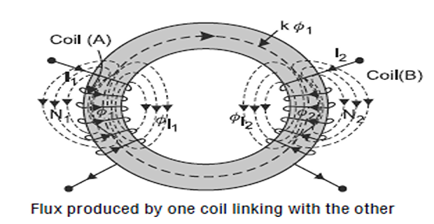
If the flux produced by one coil completely links with the other, the value of \(k\) is one and the coils are said to be magnetically tightly coupled.
Approached by two windings on a common closed iron core — a transformer, where \(k\) may exceed 0.99.
If the flux produced by one coil does not link at all with the other, the value of \(k\) is zero and the coils are said to be magnetically isolated.
Approached by coils far apart, or at right angles, or separated by a magnetic screen.
Considering coil 1 carrying current \(I_1\). The flux it produces is \(\phi_1\), of which the fraction \(k\phi_1\) links coil 2, so \(\phi_{12} = k\phi_1\):
Now considering coil 2 carrying current \(I_2\). By the same argument with the roles reversed, \(\phi_{21} = k\phi_2\):
Multiplying equations (i) and (ii), we get:
Since \(0 \le k \le 1\), the mutual inductance can never exceed the geometric mean of the two self-inductances. \(M_{\max} = \sqrt{L_1L_2}\) is an absolute ceiling set by physics, not by construction quality.
| Arrangement | \(k\) | Comment |
|---|---|---|
| Power transformer, closed iron core | 0.99+ | Nearly ideal; leakage is the design parameter |
| Ferrite-cored high-frequency transformer | 0.95–0.99 | Slightly worse; interleaving improves it |
| Air-cored coils, coaxial and close | 0.5–0.8 | Radio-frequency coupled circuits |
| Welding transformer with magnetic shunt | 0.5–0.7 | Deliberately loose, to limit current |
| Coils at right angles | ≈ 0 | Magnetically isolated by geometry |
Problem. Two coils have self-inductances of 0.20 H and 0.80 H, and a mutual inductance of 0.32 H. Find the coefficient of coupling and the maximum mutual inductance the pair could have.
Geometric mean.
Coefficient of coupling.
Maximum possible mutual inductance. At \(k = 1\),
Comment. Eighty percent of coil 1's flux reaches coil 2; the remaining twenty percent leaks. No amount of rewinding could raise \(M\) above 0.400 H while keeping these self-inductances, because \(k\) cannot exceed unity. If a problem gives you \(M > \sqrt{L_1L_2}\), the data is wrong — a useful sanity check.
Problem. An iron ring of mean length 0.5 m, cross-section 6 cm² and \(\mu_r = 900\) carries two windings of 400 and 250 turns. Assuming all the flux is common, find \(L_1\), \(L_2\) and \(M\), and verify that \(k = 1\). Then find \(k\) if the measured mutual inductance is only 0.122 H.
Reluctance.
Inductances.
Verification.
With leakage. If the measured \(M\) is 0.122 H,
Comment. The \(k = 1\) result is not a coincidence but an identity: substituting \(L_1 = N_1^2/S\), \(L_2 = N_2^2/S\) and \(M = N_1N_2/S\) gives \(M^2 = N_1^2N_2^2/S^2 = L_1L_2\) exactly. Assuming a common flux is the same thing as assuming \(k = 1\), and a measured \(k\) below unity is the direct experimental signature of leakage — which in a transformer becomes the leakage reactance of Chapter 45.
Energy Stored in an Inductor
Establishing a current in a coil requires work against the self-induced EMF, and that work is stored in the magnetic field. The derivation is short.
At any instant the source must supply power \(ei\) to overcome the back EMF, so in a time \(\mathrm{d}t\) the energy delivered is
Integrating from zero to the final current \(I\):
The last form is the one from Chapter 4, and the equivalence follows immediately from \(L = N^{2}/S\) and \(\Phi = NI/S\):
This closes a loop opened in Chapter 4, where the energy of a magnetic circuit was written in terms of reluctance and flux, and asserted without proof to equal \(\tfrac{1}{2}LI^{2}\). It also explains the design rule of Worked Example 4.5: since the gap holds most of the reluctance and \(W = \tfrac{1}{2}S\Phi^{2}\), the gap holds most of the energy.
Problem. The coil of Example 13.1 (\(L = 0.4712\) H, \(S = 5.305\times10^{5}\) AT/Wb, \(N = 500\)) carries 2 A. Find the stored energy by all three expressions.
Route 1 — from inductance and current.
Route 2 — from flux linkage. With \(\lambda = 0.9425\) Wb-t from Example 13.1,
Route 3 — from reluctance and flux. With \(\Phi = 1.885\times10^{-3}\) Wb,
Comment. Three routes through three chapters — circuit theory, flux linkage and magnetic circuits — converging on the same 0.9425 J. Use whichever form matches the data you have. Note also that this energy is returned when the current falls, not dissipated: it is the energy released as the arc when an inductive circuit is broken, and the energy that a gapped reactor is designed to store (Chapter 4).
Factors Affecting Inductance
Every factor follows directly from \(L = \mu_0\mu_r a N^{2}/l\), so the table is short and there is nothing to memorise separately.
| Change | Effect on \(L\) | Why |
|---|---|---|
| Double the turns | ×4 | \(L \propto N^{2}\) — twice the flux, twice the linkages |
| Double the core area | ×2 | \(S \propto 1/a\) |
| Double the path length | ×0.5 | \(S \propto l\) |
| Double the permeability | ×2 | \(S \propto 1/\mu_r\) |
| Insert an air gap | Falls sharply | Gap reluctance dominates (Chapter 4) |
| Drive the core into saturation | Falls | \(\mu_r\) collapses (Chapter 5) |
| Change the wire gauge | None | Affects resistance, not the magnetic circuit |
| Change the applied voltage | None* | *Unless it drives the core into saturation |
Applications
The magnetising reactance of Chapter 8 is \(X_m = 2\pi f L_m\) with \(L_m = N^{2}/S\). Leakage reactance follows from the flux that fails to link, that is, from \(1-k\).
Designed by choosing turns from the saturation limit and gap from the required \(L = N^{2}/S\) — exactly the procedure of Worked Example 4.5.
Deliberately low \(k\), achieved with a magnetic shunt, gives the large leakage reactance needed to limit current — the flux-divider effect of Chapter 3 put to work.
Stator and rotor leakage inductances and the magnetising inductance are the parameters of Chapter 64, all traceable to \(N^{2}/S\) for their respective flux paths.
A proximity sensor works because a nearby metal object changes the reluctance of the coil's flux path, and hence its inductance. LVDTs use varying mutual inductance for the same purpose.
Efficiency depends directly on \(k\) between transmitting and receiving coils. Since air-cored coupling gives \(k\) well below 1, resonant compensation is used to make up the shortfall.
Summary and Key Formulas
Self-inductance is the property of a coil by which it opposes a change of current through itself. It delays rather than prevents the change.
It opposes changing (alternating) current only and has no effect on steady direct current — the coil "exhibits its presence to AC but not to DC".
\(L = e/(\mathrm{d}I/\mathrm{d}t) = N\phi/I = N^{2}/S = N^{2}P\). Inductance is turns squared times permeance.
Mutual inductance is the property by which one coil opposes a change of current in a neighbouring coil: \(M = e_m/(\mathrm{d}I_1/\mathrm{d}t) = N_2\phi_{12}/I_1 = N_1N_2/S\). It is symmetric.
The coefficient of coupling \(k\) is the fraction of one coil's flux that links the other. \(k = 1\) means tightly coupled; \(k = 0\) means magnetically isolated.
Multiplying the two expressions for \(M\) gives \(M^{2} = k^{2}L_1L_2\), hence \(M = k\sqrt{L_1L_2}\). Since \(k \le 1\), \(M\) can never exceed \(\sqrt{L_1L_2}\).
The stored energy is \(W = \tfrac{1}{2}LI^{2} = \tfrac{1}{2}\lambda I = \tfrac{1}{2}S\Phi^{2}\) — three forms of one statement, reconciled by \(L = N^{2}/S\).
Inductance depends on geometry and material only. Wire gauge and applied voltage do not affect it, except through saturation.
| Quantity | Formula | Notes |
|---|---|---|
| Self-induced EMF | \(e = L\dfrac{\mathrm{d}I}{\mathrm{d}t}\) | defines \(L\) |
| Inductance, EMF form | \(L = \dfrac{e}{\mathrm{d}I/\mathrm{d}t}\) | henries |
| Inductance, flux form | \(L = \dfrac{N\phi}{I} = \dfrac{\lambda}{I}\) | flux linkage per ampere |
| Inductance, circuit form | \(L = \dfrac{N^{2}}{S} = N^{2}P\) | the design formula |
| Expanded | \(L = \dfrac{\mu_0\mu_r a N^{2}}{l}\) | geometry and material |
| Mutually induced EMF | \(e_m = M\dfrac{\mathrm{d}I_1}{\mathrm{d}t}\) | defines \(M\) |
| Mutual inductance, flux form | \(M = \dfrac{N_2\phi_{12}}{I_1}\) | \(\phi_{12}\) links coil 2 |
| Mutual inductance, circuit form | \(M = \dfrac{N_1N_2}{S}\) | symmetric in 1 and 2 |
| Linking flux | \(\phi_{12} = k\phi_1\) | defines \(k\) |
| Coupling relation | \(M = k\sqrt{L_1L_2}\) | \(0 \le k \le 1\) |
| Coefficient of coupling | \(k = \dfrac{M}{\sqrt{L_1L_2}}\) | from measured values |
| Maximum mutual inductance | \(M_{\max} = \sqrt{L_1L_2}\) | at \(k=1\) |
| Stored energy | \(W = \tfrac{1}{2}LI^{2} = \tfrac{1}{2}\lambda I = \tfrac{1}{2}S\Phi^{2}\) | joules; returned, not dissipated |
Common Mistakes
Writing \(L \propto N\) instead of \(N^{2}\). Doubling the turns quadruples the inductance, because both the flux and the number of linkages double.
Thinking inductance opposes current. It opposes the change of current. A steady current meets no opposition at all beyond the winding resistance.
Believing an inductor blocks DC. In the steady state it is simply a piece of wire. It blocks only the transient, and it "exhibits its presence to AC" because AC is a perpetual transient.
Confusing \(\phi_1\) with \(\phi_{12}\). The first is the total flux coil 1 produces; the second is only the part linking coil 2. They differ by the factor \(k\).
Accepting \(M > \sqrt{L_1L_2}\). Impossible, since it would require \(k > 1\). Treat it as a data error.
Using \(M = N_1N_2/S\) when the coils are not on a common core. That form already assumes \(k = 1\). For loosely coupled coils use \(M = k\sqrt{L_1L_2}\).
Forgetting the factor of one-half in the stored energy. \(W = \tfrac{1}{2}LI^{2}\) — the current builds up from zero, so the average is \(I/2\).
Treating stored energy as a loss. It is returned to the circuit when the current falls, which is why breaking an inductive circuit produces an arc.
Expecting thicker wire to raise inductance. It lowers resistance and changes nothing magnetic.
Ignoring saturation. Once \(\mu_r\) collapses, \(L\) falls with it — which is why DC-biased chokes are gapped.
Chapter Review
Where geometry is given, compute the reluctance first — every inductance question then reduces to \(N^{2}/S\).
P13.1 A coil of 300 turns is wound on a core of mean length 0.3 m, area 4 cm² and \(\mu_r = 800\). Find its inductance.
Show answer
\[S = \frac{0.3}{\left(4\pi\times10^{-7}\right)(800)\left(4\times10^{-4}\right)} = \frac{0.3}{4.021\times10^{-7}} = 7.460\times10^{5}~\mathrm{AT/Wb}\]\[L = \frac{(300)^{2}}{7.460\times10^{5}} = \frac{90\,000}{7.460\times10^{5}} = 0.1206~\mathrm{H}\]P13.2 A coil of 600 turns carries 3 A and produces a flux of 2.5 mWb. Find its inductance.
Show answer
\[L = \frac{N\phi}{I} = \frac{(600)\left(2.5\times10^{-3}\right)}{3} = \frac{1.5}{3} = 0.500~\mathrm{H}\]P13.3 The current in the coil of P13.2 falls uniformly from 4 A to 1 A in 0.02 s. Find the self-induced EMF.
Show answer
By Lenz's law this EMF acts to maintain the falling current.\[e = L\frac{\Delta I}{\Delta t} = (0.500)\frac{3}{0.02} = (0.500)(150) = 75.0~\mathrm{V}\]P13.4 The coil of P13.1 is rewound with 450 turns on the same core. Find the new inductance.
Show answer
Since \(L \propto N^{2}\) and \(S\) is unchanged:A 50 % increase in turns gives a 125 % increase in inductance.\[L' = (0.1206)\left(\frac{450}{300}\right)^{2} = (0.1206)(2.25) = 0.271~\mathrm{H}\]P13.5 Two coils have \(L_1 = 0.45\) H, \(L_2 = 0.80\) H and \(M = 0.42\) H. Find the coefficient of coupling.
Show answer
\[\sqrt{L_1L_2} = \sqrt{(0.45)(0.80)} = \sqrt{0.36} = 0.600~\mathrm{H}\]\[k = \frac{0.42}{0.600} = 0.700\]P13.6 Two coils of 0.25 H and 0.64 H have a coefficient of coupling of 0.85. Find the mutual inductance.
Show answer
\[\sqrt{L_1L_2} = \sqrt{(0.25)(0.64)} = \sqrt{0.16} = 0.400~\mathrm{H}\]\[M = k\sqrt{L_1L_2} = (0.85)(0.400) = 0.340~\mathrm{H}\]P13.7 An iron ring of mean length 0.6 m, area 8 cm² and \(\mu_r = 1500\) carries windings of 300 and 200 turns. Assuming a common flux, find \(L_1\), \(L_2\), \(M\) and \(k\).
Show answer
\[S = \frac{0.6}{\left(4\pi\times10^{-7}\right)(1500)\left(8\times10^{-4}\right)} = \frac{0.6}{1.508\times10^{-6}} = 3.979\times10^{5}~\mathrm{AT/Wb}\]\[L_1 = \frac{90\,000}{3.979\times10^{5}} = 0.2262~\mathrm{H}, \qquad L_2 = \frac{40\,000}{3.979\times10^{5}} = 0.1005~\mathrm{H}\]\[M = \frac{60\,000}{3.979\times10^{5}} = 0.1508~\mathrm{H}, \qquad \sqrt{L_1L_2} = 0.1508~\mathrm{H} \Rightarrow k = 1.000\]P13.8 A coil of 0.8 H carries 5 A. Find the stored energy, and the energy if the current is doubled.
Show answer
\[W = \tfrac{1}{2}LI^{2} = \tfrac{1}{2}(0.8)(25) = 10.0~\mathrm{J}\]Doubling the current quadruples the stored energy, since \(W \propto I^{2}\).\[W' = \tfrac{1}{2}(0.8)(100) = 40.0~\mathrm{J}\]P13.9 An iron ring of mean length 0.5 m, area 5 cm² and \(\mu_r = 2000\) carries 800 turns. Find the inductance, and the new value if a 0.5 mm air gap is cut.
Show answer
With the gap: \(S_i = 0.4995/1.2566\times10^{-6} = 3.975\times10^{5}\) and \(S_g = 0.0005/6.283\times10^{-10} = 7.958\times10^{5}\):\[S = \frac{0.5}{\left(4\pi\times10^{-7}\right)(2000)\left(5\times10^{-4}\right)} = 3.979\times10^{5}, \qquad L = \frac{640\,000}{3.979\times10^{5}} = 1.609~\mathrm{H}\]The inductance falls by a factor of 3.0 — from half a millimetre of air in half a metre of iron.\[S_{\text{total}} = 1.193\times10^{6}, \qquad L' = \frac{640\,000}{1.193\times10^{6}} = 0.536~\mathrm{H}\]P13.10 A coil is connected first to a 12 V DC supply and then to a 12 V AC supply of the same RMS value. Explain why the currents differ, and which is larger.
Show answer
On DC, once the transient has died away the current is steady, \(\mathrm{d}I/\mathrm{d}t = 0\), no self-induced EMF exists, and the current is limited only by the winding resistance: \(I = V/R\).On AC, the current is continually changing, so a self-induced EMF is always present and opposes the supply. The limiting quantity is the impedance \(Z = \sqrt{R^{2} + (2\pi fL)^{2}}\), which exceeds \(R\).
The DC current is therefore larger — often by a very large factor, as Worked Example 8.2 showed. This is precisely the meaning of "the coil exhibits its presence to AC but not to DC".
MCQ 1. Self-inductance varies with the number of turns as:
(a) \(N\) (b) \(N^{2}\) (c) \(\sqrt{N}\) (d) \(1/N\)Show answer
(b) \(N^{2}\). The flux and the number of linkages both go as \(N\).MCQ 2. In terms of the magnetic circuit, inductance equals:
(a) \(NS\) (b) \(N^{2}S\) (c) \(N^{2}/S\) (d) \(S/N^{2}\)Show answer
(c) \(N^{2}/S\) — turns squared times permeance.MCQ 3. A coil carrying a steady direct current develops a self-induced EMF of:
(a) \(LI\) (b) \(L/I\) (c) zero (d) \(I/L\)Show answer
(c) zero. With \(\mathrm{d}I/\mathrm{d}t = 0\) there is nothing to oppose.MCQ 4. Mutual inductance between two coils on a common core is:
(a) \(N_1N_2/S\) (b) \(N_1^{2}/S\) (c) \((N_1+N_2)/S\) (d) \(N_1N_2 S\)Show answer
(a) \(N_1N_2/S\) — the product of the turn counts over the shared reluctance.MCQ 5. The coefficient of coupling can have a maximum value of:
(a) 0 (b) 0.5 (c) 1 (d) unlimitedShow answer
(c) 1, when all of one coil's flux links the other.MCQ 6. If \(L_1 = 0.1\) H and \(L_2 = 0.4\) H, the mutual inductance cannot exceed:
(a) 0.1 H (b) 0.2 H (c) 0.25 H (d) 0.5 HShow answer
(b) 0.2 H, since \(M_{\max} = \sqrt{L_1L_2} = \sqrt{0.04} = 0.2\) H.MCQ 7. The energy stored in an inductor is:
(a) \(LI^{2}\) (b) \(\tfrac{1}{2}LI^{2}\) (c) \(\tfrac{1}{2}LI\) (d) \(\tfrac{1}{2}L^{2}I\)Show answer
(b) \(\tfrac{1}{2}LI^{2}\), equivalently \(\tfrac{1}{2}\lambda I\) or \(\tfrac{1}{2}S\Phi^{2}\).MCQ 8. Cutting an air gap in the core of a coil:
(a) raises \(L\) (b) lowers \(L\) (c) leaves \(L\) unchanged (d) makes \(L\) zeroShow answer
(b) lowers \(L\), often sharply, because the gap dominates the reluctance.MCQ 9. Two coils are wound at right angles to each other. Their coefficient of coupling is approximately:
(a) 1 (b) 0.7 (c) 0.5 (d) 0Show answer
(d) 0. Almost none of one coil's flux links the other — they are magnetically isolated by geometry.MCQ 10. Replacing the winding of a coil with thicker wire, all else unchanged, causes the inductance to:
(a) rise (b) fall (c) stay the same (d) become zeroShow answer
(c) stay the same. Inductance depends on turns and the magnetic circuit; wire gauge affects only resistance.
Explain why self-inductance "exhibits its presence to AC but not to DC", and relate this to the definition \(e = L\,\mathrm{d}I/\mathrm{d}t\).
Derive \(L = N^{2}/S\) from the definition of inductance, and explain physically why the dependence on turns is quadratic.
Derive \(M = k\sqrt{L_1L_2}\), stating clearly what is being multiplied and why the result is symmetric.
Explain why \(k = 1\) is automatic if you assume the two coils share a common flux, and what a measured \(k < 1\) is telling you physically.
Show that \(\tfrac{1}{2}LI^{2}\) and \(\tfrac{1}{2}S\Phi^{2}\) are the same quantity, and explain why this means the air gap stores most of the energy.
A welding transformer is deliberately built with a low coefficient of coupling. Explain what this achieves and how it is done.
Inductance is said to be electrical inertia. Develop the analogy fully, identifying the mechanical counterpart of current, voltage, inductance and stored energy.
Chapter 14 combines inductances in series and parallel. The interesting cases are those in which mutual inductance is present: connecting two coupled coils so that their fluxes aid gives \(L = L_1 + L_2 + 2M\), and so that they oppose gives \(L_1 + L_2 - 2M\). Subtracting the two measurements yields \(M\) directly — the standard laboratory method for determining a quantity that cannot be measured on its own.
From Chapter 15 the treatment changes character. Energy and coenergy replace circuit reasoning as the primary tool, and the \(\tfrac{1}{2}LI^{2}\) of Section 13-6 becomes the starting point for the general energy-balance method. By Chapter 18 that method delivers force and torque from a stored-energy function alone — and every machine in Parts 2 to 6 becomes a special case of one result.