By the end of this chapter you should be able to:
State Lenz's law and explain the meaning of the negative sign in Faraday's law.
Determine the polarity of the coil face and the direction of the induced current when a magnet approaches or recedes.
Apply the right-hand thumb rule and Maxwell's corkscrew rule to find the field around a current.
Apply Fleming's right-hand rule to find the direction of induced EMF in a generator.
Apply Fleming's left-hand rule to find the direction of force in a motor, and say which rule belongs to which machine.
Show that Lenz's law is a statement of energy conservation, and that the opposite would permit perpetual motion.
Verify the power balance for a conductor sliding on rails: mechanical power in equals electrical power out.
Explain back EMF in a motor as Lenz's law in action, and compute the current it prevents.
Introduction
Chapter 10 established the magnitude of the induced EMF and deliberately set the minus sign aside. This chapter picks it up. That single sign carries more physics than the rest of the equation, because it is the reason a generator needs a prime mover, the reason a motor draws less current as it speeds up, and — ultimately — the reason electromagnetic perpetual motion is impossible.
Alongside Lenz's law come the hand rules: a set of mnemonics for turning the abstract cross products of electromagnetism into something you can work out with your fingers in an examination hall. Three are needed, and students routinely confuse them. The right-hand thumb rule gives the field around a current. Fleming's right-hand rule gives the induced EMF in a generator. Fleming's left-hand rule gives the force in a motor.
Between them, Faraday's law and Lenz's law completely determine every induced EMF in this book: one gives the size, the other the sign.
Lenz's Law
Lenz's law obeys Newton's third law of motion and the conservation of energy.
Lenz's law is based on Faraday's law of induction.
When an EMF is generated by a change in magnetic flux according to Faraday's law, the polarity of the induced EMF is such that it produces a current whose magnetic field opposes the change which produces it.
The negative sign used in Faraday's law of electromagnetic induction indicates that the induced EMF and the change in magnetic flux have opposite signs.
Note carefully what is opposed. It is not the flux, and it is not the magnet. It is the change. If the flux is increasing, the induced current acts to reduce it; if the flux is decreasing, the induced current acts to maintain it. The same coil therefore behaves in opposite ways depending only on which direction the flux is moving — which is exactly what the two cases of Sections 11-3 and 11-4 demonstrate.
Case 1 — Magnet Approaching
When the north pole of the magnet is approaching towards the coil, the flux \(\phi\) linking to the coil increases.
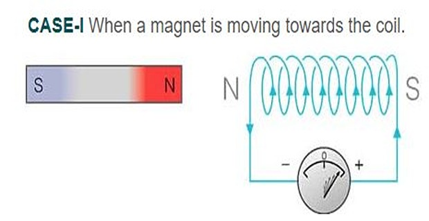
- According to Faraday's law of electromagnetic induction, when \(\phi\) changes, an EMF — and hence a current \(I\) — is induced in the coil, which will create its own magnetic field.
- According to Lenz's law, this magnetic field created will oppose the increase in \(\phi\) through the coil. This is possible only if the approaching coil side attains north polarity, since similar poles repel each other.
- Once the magnetic polarity of the coil side is known, the direction of the induced current can easily be determined by applying the right-hand rule.
- In this case, the current flows in the anticlockwise direction when viewed from the magnet's side.
Because the coil presents a north pole to the magnet's north pole, the two repel. The magnet is pushed back the way it came, and whoever is moving it must do work against that repulsion.
That work is precisely the source of the electrical energy that appears in the coil. Section 11-7 makes the accounting exact.
Case 2 — Magnet Receding
When the north pole of the magnet is moving away from the coil, the flux \(\phi\) linking to the coil decreases.

- According to Faraday's law of electromagnetic induction, an EMF — and hence a current \(I\) — is induced in the coil, which will create its own magnetic field.
- According to Lenz's law, the magnetic field created will oppose the decrease in \(\phi\) through the coil. This is possible only if the approaching coil side attains south polarity, since dissimilar poles attract each other.
- Once we know the magnetic polarity of the coil side, we can easily determine the direction of the induced current by applying the right-hand rule.
- In this case, the current flows in the clockwise direction.
Problem. The south pole of a bar magnet is moved towards a coil. Determine the polarity of the near coil face, the direction of the induced current as seen from the magnet, and the mechanical force on the magnet.
Step 1 — is the flux increasing or decreasing? The magnet is approaching, so the flux linking the coil increases. (Its direction is now into the magnet's south pole, opposite to Case 1, but the increase is what matters.)
Step 2 — what polarity must the coil present? To oppose an increase, the coil must repel the approaching pole. Like poles repel, so the near coil face must become a south pole.
Step 3 — which way is the current? Applying the right-hand thumb rule, a face presenting a south pole to the observer carries current clockwise as seen from that side.
Force. Two south poles face each other, so the magnet is repelled — pushed back the way it came, exactly as in Case 1.
Comment. Compare with Case 1. Reversing the magnet reversed the current direction but not the mechanical outcome: an approaching magnet is always repelled, and a receding one always attracted, whichever pole leads. Lenz's law opposes the motion, not the polarity — which is why it can be an expression of energy conservation, as Section 11-7 shows.
The Right-Hand Thumb Rule
For finding the directions of magnetic field or current, the following rule is used.
If the fingers of the right hand are placed around the wire so that the thumb points in the direction of current flow, then the curling of the fingers will show the direction of the magnetic field produced by the wire.

Applied to a coil. The same rule works in reverse for a solenoid or coil: curl the fingers of the right hand in the direction the current circulates, and the thumb points towards the face that behaves as a north pole. This is the form used in steps 3 and 4 of Sections 11-3 and 11-4.
Two equivalent statements of the same geometry are also in common use:
Imagine driving a right-handed corkscrew along the direction of the current. The direction in which the handle must be turned gives the direction of the magnetic field.
Viewed from the end, a coil face carrying anticlockwise current is a North pole; one carrying clockwise current is a South pole. The letters help: the arrowheads of an N and an S follow the respective senses.
Fleming's Hand Rules
The thumb rule relates a current to the field it produces. A different problem arises when a conductor sits in an externally applied field: which way does the induced EMF point, and which way does the force act? Fleming's two rules answer these, and the difficulty is remembering which hand goes with which.
Hold the first three fingers of the right hand mutually perpendicular:
Forefinger → Field
ThuMb → Motion
SeCond finger → Current (induced EMF)
Use when the motion is given and the EMF is wanted — the generator problem, \(e = Blv\).
Hold the first three fingers of the left hand mutually perpendicular:
Forefinger → Field
SeCond finger → Current
ThuMb → Motion (force)
Use when the current is given and the force is wanted — the motor problem, \(F = BIl\).
moTor → lefT hand. Both contain a T.
geneRator → Right hand. Both contain an R.
The finger assignments are identical in both rules — Forefinger for Field, seCond for Current, thuMb for Motion or force. Only the hand differs, and the letter trick settles that in a second.
Why two rules at all? Because the two situations are physically opposite. In a generator, motion is the cause and current the effect. In a motor, current is the cause and motion the effect. Lenz's law demands that the effect oppose the cause in each case, and swapping hands is precisely what encodes that reversal.
Problem. A horizontal conductor lies in a magnetic field directed from left to right (west to east). (a) As a generator, the conductor is moved vertically upward. Which way does the induced current flow? (b) As a motor, current is passed through the same conductor in the direction found in (a). Which way is the force, and how does this illustrate Lenz's law?
(a) Generator — right hand. Point the forefinger east (field) and the thumb upward (motion). The second finger, held perpendicular to both, then points south — that is, out of the page if the field is drawn to the right and the motion upward. The induced current flows in that direction.
(b) Motor — left hand. Now point the forefinger east (field, unchanged) and the second finger in the current direction found above (out of the page). The thumb of the left hand then points downward.
Comment. This is Lenz's law made visible. The conductor was moved upward to generate the current; the force produced by that same current is downward, opposing the motion that created it.
The two rules are not independent facts to memorise — the second follows from the first plus Lenz's law. If Fleming's left-hand rule used the right hand instead, the force would aid the motion, the conductor would accelerate without limit and generate ever more current from nothing. Section 11-7 develops that argument properly.
Lenz's Law and Energy Conservation
Lenz's law is often presented as an experimental rule about directions. It is more than that: it is a necessary consequence of energy conservation, and the argument is short enough to be worth following in full.
Imagine the induced current aided the change instead of opposing it. Push a magnet towards a coil, and the coil would attract it, pulling it in faster. Faster motion means a greater rate of change of flux, hence a larger EMF, hence a larger current, hence a stronger attraction — and so on without limit.
The magnet would accelerate indefinitely while simultaneously delivering ever-increasing electrical energy to the coil, with nothing supplying either. This is a perpetual motion machine of the first kind. Since energy cannot be created, the induced effect must oppose its cause, and Lenz's law is the only possibility.
The quantitative statement. Consider a conductor of length \(l\) sliding at velocity \(v\) along frictionless rails in a field \(B\), with the circuit closed through a resistance \(R\). Four steps complete the accounting:
- The EMF. From Chapter 10, \(e = Blv\).
- The current. \(i = e/R = Blv/R\).
- The force. That current sits in the field, so it experiences \(F = Bil = B^{2}l^{2}v/R\) — and by Lenz's law it opposes the motion.
- The power. To keep the rod moving at constant speed an external agent must supply \(P_{\text{mech}} = Fv\).
The two expressions are identical. Not approximately, not to within an efficiency — identically equal. Every joule of mechanical work done against the opposing force reappears as electrical energy in the resistance. This is the energy-conversion identity of Chapter 1, derived from Lenz's law alone.
Problem. A conducting rod 0.4 m long slides on frictionless rails at 6 m/s in a field of 0.8 T perpendicular to the plane of the rails. The total circuit resistance is 0.5 \(\Omega\). Find the induced EMF, the current, the force opposing the motion, and verify the power balance.
Induced EMF.
Current.
Opposing force.
Power balance.
And as a third check, \(ei = (1.92)(3.84) = 7.373\) W \(\checkmark\)
Comment. Three independent routes give the same 7.373 W. Note also the structure of the result: \(F = B^{2}l^{2}v/R\) is proportional to speed, which makes this arrangement a perfect viscous damper. That is exactly the eddy-current braking of Chapter 7, and it explains why such brakes fade to nothing at standstill — at \(v = 0\) there is no EMF, no current and no force.
Problem. The rod of Example 11.3 is now vertical, sliding on vertical rails under gravity, with a mass of 0.050 kg. Find the terminal velocity at which it stops accelerating. Take \(g = 9.81\) m/s².
Condition. At terminal velocity the electromagnetic force exactly balances the weight:
Solving.
Check. At this speed the dissipated power should equal the rate of loss of potential energy:
Comment. This is why a magnet dropped down a copper tube falls slowly and steadily rather than accelerating: the induced currents produce a retarding force proportional to speed, and the magnet settles at whatever velocity makes that force equal its weight. No energy has vanished — the lost potential energy appears as \(i^{2}R\) heating in the tube.
Back EMF — Lenz's Law in a Motor
The most consequential application of Lenz's law in this book is the back EMF of a motor, introduced in Chapter 1 and now explicable.
When a motor's armature rotates, its conductors move through the field, so by Faraday's law an EMF is induced in them. By Lenz's law that EMF must oppose the cause of the rotation — which is the applied voltage. Hence:
At standstill \(E = 0\) and only \(R_a\) — a fraction of an ohm — limits the current. As the motor speeds up, \(E\) rises and the current falls automatically. Load the motor and it slows slightly, \(E\) falls, current rises, torque rises: the machine draws exactly the current its load demands, with no controller of any kind.
Chapter 1 warned that back EMF is not a loss but the very mechanism of conversion, since \(EI_a\) is the power converted to mechanical form. Lenz's law explains why: an EMF that aided the supply would deliver energy to the shaft and increase the current drawn — energy from nowhere again.
Problem. A 230 V DC motor has an armature resistance of 0.5 \(\Omega\) and draws 20 A when running normally. Find the back EMF, and the current that would flow if the armature were held stationary. Account for the power.
Back EMF.
Current at standstill. With the rotor held, \(E = 0\):
which is 23 times the running current — enough to destroy the winding in seconds.
Power accounting at normal speed.
Check: \(4600 = 4400 + 200\) \(\checkmark\)
Comment. The back EMF is doing two jobs at once. It limits the current to a twenty-third of what the winding resistance alone would allow, and the 4400 W associated with it is the mechanical output. Lenz's law is not a protective afterthought bolted onto the machine — it is the machine. This is also why a DC motor needs a starter: at the instant of switching on there is no back EMF, and external resistance must stand in for it until the machine has run up.
Applications
Because back EMF is absent at standstill, DC motors above a fraction of a kilowatt need series resistance during run-up, cut out progressively as the EMF builds. Chapter 37 designs the starter.
The \(F \propto v\) result of Example 11.3 gives contactless viscous damping — instrument movements, energy-meter discs, train and roller-coaster brakes, all working directly from Lenz's law.
Drive a motor faster than its no-load speed and the back EMF exceeds the supply. Current reverses, the machine becomes a generator, and the vehicle's kinetic energy returns to the battery — Lenz's law running in reverse.
The rotor currents are induced by the rotating field and, by Lenz's law, act to reduce the relative motion — which is to say, they drag the rotor after the field. The whole machine is Lenz's law made continuous (Chapter 58).
Interrupt the current in an inductor and Lenz's law opposes the collapse with a large voltage spike. Freewheel diodes and snubbers exist entirely to give that opposition somewhere harmless to go.
Fault currents in adjacent windings produce enormous Lenz-law forces trying to force the windings apart. Mechanical bracing to withstand them is a major part of transformer design.
Summary and Key Formulas
Lenz's law: the polarity of the induced EMF is such that it produces a current whose magnetic field opposes the change which produces it. It obeys Newton's third law and conservation of energy.
The negative sign in \(\varepsilon = -N\,\partial\Phi/\partial t\) indicates that the induced EMF and the change in flux have opposite signs.
What is opposed is the change, not the flux. An approaching magnet is repelled; a receding one is attracted — whichever pole leads.
Case 1 (N pole approaching): flux increases, coil face becomes N, current anticlockwise.
Case 2 (N pole receding): flux decreases, coil face becomes S, current clockwise.
Right-hand thumb rule: thumb along the current, curled fingers give the field. For a coil, curl the fingers with the current and the thumb points to the north face.
Fleming's right hand → geneRator; Fleming's left hand → moTor. In both, Forefinger = Field, seCond = Current, thuMb = Motion or force.
For a sliding rod, \(F = B^{2}l^{2}v/R\) opposes the motion and \(P_{\text{mech}} = P_{\text{elec}}\) exactly.
Back EMF is Lenz's law in a motor: it limits the current to \((V-E)/R_a\) and its product with armature current is the converted power.
| Rule | Hand | Given | Found | Used for |
|---|---|---|---|---|
| Right-hand thumb | Right | Current | Field around it | Coil polarity, Lenz problems |
| Fleming's right hand | Right | Field + motion | Induced current | Generators |
| Fleming's left hand | Left | Field + current | Force | Motors |
| Quantity | Formula | Notes |
|---|---|---|
| Faraday–Lenz law | \(\varepsilon = -N\dfrac{\partial\Phi}{\partial t}\) | sign is Lenz's law |
| Motional EMF | \(e = Blv\) | direction by Fleming's right hand |
| Induced current | \(i = \dfrac{Blv}{R}\) | closed circuit |
| Opposing force | \(F = Bil = \dfrac{B^{2}l^{2}v}{R}\) | proportional to speed |
| Mechanical power | \(P_{\text{mech}} = Fv = \dfrac{B^{2}l^{2}v^{2}}{R}\) | supplied by the mover |
| Electrical power | \(P_{\text{elec}} = i^{2}R\) | equals \(P_{\text{mech}}\) exactly |
| Terminal velocity | \(v_t = \dfrac{mgR}{B^{2}l^{2}}\) | falling rod or magnet in a tube |
| Back EMF | \(E = V - I_aR_a\) | motor convention |
| Armature current | \(I_a = \dfrac{V-E}{R_a}\) | at standstill \(E=0\) |
| Converted power | \(P_{\text{conv}} = EI_a\) | the mechanical output |
Common Mistakes
Thinking Lenz's law opposes the flux. It opposes the change in flux. A decreasing flux is helped by the induced current, not opposed.
Using the wrong hand. geneRator → Right; moTor → lefT. Match the letters and the error disappears.
Confusing the right-hand thumb rule with Fleming's right-hand rule. The first relates a current to the field it creates; the second relates motion in an external field to the induced current. Different problems entirely.
Forgetting to state the viewing direction. "Clockwise" is meaningless without saying from which side the coil is viewed. Always specify.
Treating the opposing force as a loss. The work done against it is the electrical output. Without it there would be no energy conversion at all.
Believing back EMF wastes power. \(EI_a\) is the converted power. The waste is \(I_a^2R_a\), which back EMF actually reduces by limiting the current.
Expecting eddy-current brakes to hold a stationary load. \(F \propto v\), so the force vanishes at standstill. A friction brake is still needed to park.
Assuming the induced current always flows. The EMF appears regardless, but current — and hence the opposing force — requires a closed circuit. An open-circuited generator is easy to turn.
Dropping the minus sign as "just a convention". It is the difference between a working machine and a perpetual motion machine.
Mixing two direction rules within one problem. Pick one convention and carry it through; most sign errors come from switching halfway.
Chapter Review
For direction problems, follow the three-step routine of Section 11-2 and always state the viewing direction.
P11.1 The south pole of a magnet is moved away from a coil. Find the polarity of the near coil face, the current direction seen from the magnet, and the force on the magnet.
Show answer
Step 1: receding magnet → flux decreases.
Step 2: to oppose a decrease the coil must attract the departing pole, so the near face must become the opposite pole — a north pole.
Step 3: a face presenting north to the observer carries current anticlockwise as seen from that side.
Force: north attracts south, so the magnet is attracted — held back as it leaves. Work must still be done to remove it.P11.2 A rod 0.6 m long slides at 4 m/s on frictionless rails in a field of 1.1 T. Circuit resistance is 0.8 \(\Omega\). Find \(e\), \(i\), \(F\), and verify the power balance.
Show answer
\[e = Blv = (1.1)(0.6)(4) = 2.64~\mathrm{V}, \qquad i = \frac{2.64}{0.8} = 3.30~\mathrm{A}\]\[F = Bil = (1.1)(3.30)(0.6) = 2.178~\mathrm{N}\]\[P_{\text{mech}} = Fv = (2.178)(4) = 8.712~\mathrm{W}, \qquad P_{\text{elec}} = i^{2}R = (10.89)(0.8) = 8.712~\mathrm{W} \;\checkmark\]P11.3 A rod of mass 0.080 kg and length 0.5 m falls on vertical rails in a field of 0.9 T, with circuit resistance 0.4 \(\Omega\). Find the terminal velocity.
Show answer
At that speed the rod dissipates \(mgv_t = (0.080)(9.81)(1.550) = 1.216\) W as heat in the resistance.\[v_t = \frac{mgR}{B^{2}l^{2}} = \frac{(0.080)(9.81)(0.4)}{(0.81)(0.25)} = \frac{0.3139}{0.2025} = 1.550~\mathrm{m/s}\]P11.4 Which of Fleming's rules applies to (a) an alternator stator conductor, (b) a DC motor armature conductor, (c) a conductor being pushed through a field to generate current? State the hand in each case.
Show answer
(a) Alternator — generating — right hand.
(b) DC motor — producing force — left hand.
(c) Generating — right hand.
The test is always: which quantity is the cause? Motion causing current → right; current causing motion → left.P11.5 A 400 V DC motor has an armature resistance of 0.8 \(\Omega\) and draws 30 A. Find the back EMF, the standstill current, and the converted power.
Show answer
\[E = 400 - (30)(0.8) = 400 - 24 = 376~\mathrm{V}\]\[I_{\text{standstill}} = \frac{400}{0.8} = 500~\mathrm{A} \quad (16.7\times \text{ the running current})\]Check: input \(= VI_a = (400)(30) = 12\,000\) W and copper loss \(= I_a^{2}R_a = (900)(0.8) = 720\) W, so the converted power is \(12\,000 - 720 = 11\,280\) W \(\checkmark\)\[P_{\text{conv}} = EI_a = (376)(30) = 11\,280~\mathrm{W}\]P11.6 For the rod of P11.2, find the braking force at 2 m/s and at 8 m/s. What is the force at standstill?
Show answer
Since \(F = B^{2}l^{2}v/R\) is proportional to \(v\), and \(F = 2.178\) N at 4 m/s:The force vanishes at standstill — no motion, no EMF, no current, no force. This is the defining limitation of every eddy-current brake.\[F(2) = 1.089~\mathrm{N}, \qquad F(8) = 4.356~\mathrm{N}, \qquad F(0) = 0\]P11.7 A vertical wire carries current upward. Using the right-hand thumb rule, state the direction of the magnetic field to the north of the wire and to the south of it.
Show answer
With the right thumb pointing upward (the current), the fingers curl anticlockwise when viewed from above. Therefore, viewed from above, the field points:North of the wire: towards the west.
South of the wire: towards the east.
P11.8 Explain, using Lenz's law, why an open-circuited generator is much easier to turn than one supplying a load.
Show answer
With the circuit open, an EMF is induced but no current flows. With no current there is no \(F = Bil\) force, so nothing opposes the rotation except friction and windage.Close the circuit and current flows; by Lenz's law it produces a torque opposing the rotation, and the prime mover must now supply \(P = \omega T\) to overcome it. That mechanical power is exactly the electrical power delivered to the load. The effort required to turn a generator is the load, transmitted magnetically across the air gap.
P11.9 A strong magnet is dropped down a long vertical copper tube. Describe and explain its motion. Would an aluminium tube behave differently? What about a plastic one?
Show answer
The magnet falls slowly at a nearly constant speed. Its motion induces circulating currents in the tube wall; by Lenz's law these oppose the change, retarding the magnet. It settles at the terminal velocity where the retarding force equals its weight.Aluminium: similar but faster, since aluminium's resistivity is about 1.6 times copper's, so the induced currents — and hence the retarding force — are correspondingly smaller.
Plastic: no effect at all. Plastic is an insulator, no currents can circulate, and the magnet falls freely under gravity. The effect requires a conductor, not a magnetic material — copper and aluminium are both non-magnetic.
P11.10 Suppose the induced current aided rather than opposed the change producing it. Trace the consequences for a magnet pushed towards a coil.
Show answer
The coil would attract the approaching magnet, accelerating it. Faster motion → greater \(\mathrm{d}\Phi/\mathrm{d}t\) → larger EMF → larger current → stronger attraction → faster still. The magnet would accelerate without limit while the coil dissipated ever-increasing \(i^{2}R\) heat, with no source supplying either the kinetic or the electrical energy.This is a perpetual motion machine of the first kind, which violates conservation of energy. Lenz's law is therefore not an independent experimental fact but a necessary consequence of energy conservation.
MCQ 1. Lenz's law states that the induced current opposes:
(a) the flux (b) the change in flux (c) the applied voltage (d) the resistanceShow answer
(b) the change in flux. A decreasing flux is sustained, not opposed.MCQ 2. The negative sign in \(\varepsilon = -N\,\mathrm{d}\Phi/\mathrm{d}t\) expresses:
(a) Ohm's law (b) Lenz's law (c) Ampère's law (d) a sign convention onlyShow answer
(b) Lenz's law — the induced EMF and the change in flux have opposite signs.MCQ 3. When the north pole of a magnet approaches a coil, the near coil face becomes:
(a) a north pole (b) a south pole (c) unmagnetised (d) alternately bothShow answer
(a) a north pole, so that like poles repel and the approach is opposed.MCQ 4. Fleming's right-hand rule applies to:
(a) motors (b) generators (c) transformers (d) all three equallyShow answer
(b) generators. geneRator → Right hand.MCQ 5. In Fleming's rules, the second finger represents:
(a) field (b) current (c) motion (d) fluxShow answer
(b) current — seCond finger, Current. This is the same in both rules.MCQ 6. For a rod sliding on rails, the retarding force varies with speed as:
(a) independent of \(v\) (b) proportional to \(v\) (c) proportional to \(v^{2}\) (d) inversely as \(v\)Show answer
(b) proportional to \(v\), since \(F = B^2l^2v/R\). This gives viscous damping.MCQ 7. The mechanical power supplied to a sliding rod compared with the electrical power dissipated is:
(a) greater (b) smaller (c) exactly equal (d) unrelatedShow answer
(c) exactly equal — both equal \(B^2l^2v^2/R\). This is Lenz's law enforcing energy conservation.MCQ 8. The back EMF of a DC motor at standstill is:
(a) maximum (b) equal to the supply (c) zero (d) negativeShow answer
(c) zero, because nothing is moving. This is why starting current is dangerously large and why starters exist.MCQ 9. An eddy-current brake produces zero force when:
(a) the speed is maximum (b) the speed is zero (c) the field is maximum (d) neverShow answer
(b) the speed is zero. No relative motion means no EMF, no current and no force.MCQ 10. If the induced effect aided rather than opposed its cause, the result would be:
(a) a more efficient machine (b) perpetual motion, violating energy conservation (c) no change (d) reversed polarity onlyShow answer
(b) perpetual motion, violating energy conservation. This is why Lenz's law must hold.
State Lenz's law and explain precisely what quantity is opposed. Why is it wrong to say the induced current opposes the flux?
Show that Lenz's law follows from energy conservation rather than being an independent experimental result.
Explain why an approaching magnet is repelled and a receding one attracted, regardless of which pole faces the coil.
Distinguish clearly between the right-hand thumb rule and Fleming's right-hand rule. Give a problem for which each is the appropriate tool.
Explain why the motor rule uses the left hand while the generator rule uses the right, and relate this to Lenz's law.
The force opposing a sliding rod is often described as a nuisance. Argue that it is instead the essential mechanism of energy conversion.
Explain why a DC motor is self-regulating — drawing more current when loaded and less when unloaded — with no controller of any kind.
Faraday's law now has both a magnitude and a direction. Chapter 12 divides induced EMF into its two natural families: statically induced EMF, where the conductor is stationary and the flux varies in time, and dynamically induced EMF, where the flux is steady and the conductor moves. The first is the transformer in its purest form; the second is the generator.
Chapters 13 and 14 then introduce self and mutual inductance, showing that inductance is nothing more than turns squared times permeance — the result Chapter 2 hinted at. From Chapter 15 the energy methods begin, and by Chapter 18 force and torque follow from a stored-energy function alone. At that point every machine in Parts 2 to 6 becomes a special case.