By the end of this chapter you should be able to:
Explain the physical origin of hysteresis loss in terms of the opposition encountered when magnetisation is reversed.
Derive \(w_h = \oint H\,\mathrm{d}B\) from the energy supplied to a magnetised core, and identify it with the loop area.
State and apply Steinmetz's law, \(P_h = k_h f B_{\max}^{n} V\), and explain what \(k_h\) and \(n\) represent.
Scale a measured loss to a new frequency or flux density, including the case of constant applied voltage where the two change together.
Explain how the shape of the loop governs the choice of material for a core, a magnet, a relay and a memory element.
Identify where in a machine or transformer hysteresis loss occurs, and why it is classed as a constant loss.
Separate hysteresis from eddy-current loss using measurements at two frequencies.
List the practical measures that reduce hysteresis loss and explain the design trade-off each involves.
Introduction
Chapter 5 established that the hysteresis loop encloses an area, and asserted without proof that the area represents energy lost as heat. This chapter proves it, quantifies it, and shows what follows.
What follows is a great deal. Hysteresis loss is one of the two components of core loss — the "constant loss" that has appeared in every efficiency calculation since Chapter 1. It is present in every transformer and every rotating machine, it continues at full value whether the machine is loaded or idling, and over a twenty-year life it can cost several times the price of the iron that produces it. A distribution transformer energised continuously but lightly loaded may dissipate more energy in core loss than in copper loss over its lifetime.
The chapter also settles a question left hanging since Chapter 5: why silicon steel? The answer is not that silicon steel is the most permeable material available, nor the one with the highest saturation. It is that among materials with adequate saturation, it has the narrowest loop that can be manufactured cheaply in tonnage quantities — and the loop width is what the electricity bill is proportional to.
The Physical Origin
The classical account, which remains the clearest way to fix the idea, runs as follows.
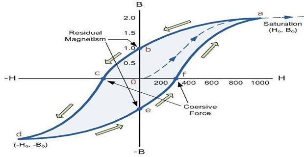
When a magnetising force \(H\) is applied, the magnetic material is magnetised and the molecular magnets are lined up in a particular direction.
When \(H\) is reversed, the internal friction of the molecular magnets opposes the reversal of magnetism, resulting in hysteresis.
To overcome this internal friction — that is, to wipe off the residual magnetism — a part of the magnetising force is used up.
The work done by \(H\) against this internal friction produces heat.
This energy, wasted as heat because of hysteresis, is called hysteresis loss.
Two consequences follow immediately, and both are stated in the classical account:
Hysteresis loss occurs in all the magnetic parts of electrical machines where there is a reversal of magnetisation — which is to say, in every transformer core and in the whole of every rotating machine's magnetic circuit.
The loss results in wastage of energy in the form of heat.
Consequently it raises the temperature of the machine, which is undesirable — and, as Chapter 1 showed, temperature is what a machine's rating is really about.
Therefore a suitable magnetic material must be selected for the construction of such parts. Silicon steel is the usual choice, being the material in which hysteresis loss is minimum among those with adequate saturation density and acceptable cost.
Energy per Cycle — Derivation
The claim that loop area equals energy is not an analogy. It follows in four lines from the definitions already established.
Consider a core of cross-section \(A\) and mean length \(l\), so of volume \(V = Al\), wound with \(N\) turns carrying current \(i\). As the flux changes, the coil develops a back EMF
The source must supply power \(ei\) to drive the flux against this EMF. In a time \(\mathrm{d}t\) the energy supplied is therefore
Now use Ampère's law from Chapter 2, \(Ni = Hl\), to eliminate the current:
Around one complete cycle the integral does not vanish. Its value is the area enclosed by the hysteresis loop, in joules per cubic metre per cycle. If the material were lossless the loop would collapse to a single line, the outward and return paths would coincide, and the integral would be zero.
The interpretation of the individual quadrants is worth spelling out, because it makes clear that hysteresis loss is a difference between two much larger quantities:
Multiplying by the number of cycles per second and by the volume gives the power:
When the loop is measured on a plotter or oscilloscope, its area is obtained in square centimetres of graph paper and converted using both axis scales:
where \(s_H\) is the horizontal scale in AT/m per cm and \(s_B\) the vertical scale in tesla per cm.
Problem. A hysteresis loop for a ring specimen encloses 32 cm² when plotted to scales of 1 cm = 150 AT/m and 1 cm = 0.12 T. The specimen has a mass of 8.0 kg and a density of 7650 kg/m³, and is magnetised at 50 Hz. Find the hysteresis loss in watts and in watts per kilogram.
Energy per unit volume per cycle.
Volume from mass and density.
Power.
Comment. Specific loss in watts per kilogram is how core steel is actually sold and specified, because it lets a designer compute the loss of any core from its mass alone. A figure of 3.77 W/kg indicates a fairly ordinary grade worked reasonably hard; premium grain-oriented steel at moderate flux density would be well under 1 W/kg. Note also that this figure covers hysteresis only — the eddy-current component of Chapter 7 must be added to get the total core loss.
Steinmetz's Law
Measuring a loop for every design is impractical. In the 1890s Charles Steinmetz observed that for a given material the loop area follows a simple power law in the peak flux density, and the resulting empirical formula is still what designers use.
\(k_h\) is the Steinmetz coefficient, a property of the material; \(n\) is the Steinmetz exponent. Steinmetz found \(n = 1.6\) for the materials of his day; modern steels give values between about 1.6 and 2.0, and the figure should be taken from the manufacturer's data rather than assumed.
Read the law carefully, because the two variables behave quite differently:
\(P_h \propto f\) — linear in frequency, because the loop is traversed \(f\) times per second and each traversal costs the same energy.
\(P_h \propto B_{\max}^{n}\) with \(n > 1\) — super-linear in flux density. This is the punishing term. A 10 % rise in \(B_{\max}\) raises the loss by about 16 %, and a 20 % rise by about 34 %.
\(P_h \propto V\) — proportional to the volume of iron, or equivalently to its mass.
| Material | \(k_h\) | Relative loss | Typical use |
|---|---|---|---|
| Hard steel | ~7000 | 37 × | Permanent magnets — never cycled |
| Cast iron | ~3000 | 16 × | Frames, yokes carrying steady flux |
| Cast steel | ~750 | 3.9 × | DC machine yokes and poles |
| Silicon steel (CRGO) | ~190 | 1 × | Transformer and AC machine cores |
| Permalloy | ~30 | 0.16 × | Instrument transformers, shielding |
A common examination trap, and a real design issue. From the EMF equation of Chapter 41, the peak flux in a transformer at a fixed applied voltage is
So raising the frequency of the supply while holding the voltage constant does not simply raise the hysteresis loss in proportion to \(f\) — the flux density falls at the same time. Combining the two effects:
With \(n = 1.6\) this gives \(P_h \propto f^{-0.6}\): the hysteresis loss actually falls as frequency rises at constant voltage. Always ask whether the flux density is being held fixed or the voltage is.
Problem. A transformer core has a hysteresis loss of 120 W at 50 Hz and \(B_{\max} = 1.2\) T. Taking \(n = 1.7\), find the loss at (a) 60 Hz with \(B_{\max}\) unchanged, (b) 50 Hz with \(B_{\max} = 1.4\) T, and (c) 60 Hz at the same applied voltage.
(a) Frequency alone. Flux density fixed, so \(P_h \propto f\):
(b) Flux density alone. Frequency fixed, so \(P_h \propto B_{\max}^{1.7}\):
A 16.7 % rise in flux density produced a 30 % rise in loss.
(c) Constant voltage. Now both change. Since \(B_{\max} \propto 1/f\):
Comment. Compare (a) and (c). Both are "run the transformer at 60 Hz", and they differ by 36 %, in opposite directions from the original figure. The question "what happens to the loss at higher frequency?" has no answer until you say what is being held constant. Case (c) is why a transformer designed for 50 Hz operates happily on a 60 Hz supply at rated voltage, while the reverse — a 60 Hz transformer on 50 Hz — raises the flux density by 20 % and can drive the core into saturation.
Importance of the Hysteresis Loop
The loop is not merely a curiosity of measurement. Its shape is the single most useful summary of what a magnetic material is good for, and four features of it map directly onto four different applications.
The enclosed area is the energy dissipated per cycle. For anything that is magnetised and demagnetised repeatedly — a transformer core, a machine core — the area must be as small as possible. This is the dominant criterion for AC applications.
A higher saturation flux density means the same flux passes through less iron, so the core is smaller, lighter and cheaper. This is why silicon steel (about 2.0 T) is preferred to ferrite (about 0.4 T) wherever frequency permits.
A wide loop resists demagnetisation. For a permanent magnet this is exactly what is wanted; for a core it is a disaster, since width and area go together. The same feature is desirable in one application and fatal in the other.
A nearly rectangular loop gives two stable remanent states with a sharp switching threshold — the requirement for magnetic recording and for the ferrite core memory that preceded semiconductor RAM.

| Loop feature | Wanted for a core | Wanted for a magnet | Wanted for memory |
|---|---|---|---|
| Enclosed area | As small as possible | Irrelevant — never cycled | Small, to switch cheaply |
| Coercivity \(H_c\) | Very low | Very high | Moderate and well defined |
| Retentivity \(B_r\) | Low (but some helps self-excitation) | Very high | High, close to \(B_{\text{sat}}\) |
| Saturation \(B_{\text{sat}}\) | High, to keep the core small | High | Moderate |
| Shape | Narrow and steep | Wide and full | Rectangular |
| Example | Silicon steel, permalloy | NdFeB, Alnico, ferrite magnet | Square-loop ferrite |
Problem. A core of volume 0.015 m³ operates at 50 Hz and \(B_{\max} = 1.3\) T. Using Table 6.1 with \(n = 1.6\), compare the hysteresis loss if it is made of cast iron, cast steel, or silicon steel.
Common factor.
Cast iron (\(k_h = 3000\)):
Cast steel (\(k_h = 750\)):
Silicon steel (\(k_h = 190\)):
Comment. Cast iron loses 15.8 times what silicon steel does, in the same volume under identical conditions. Over a year of continuous operation the difference is
— at ₹8.00 per kWh, about ₹225,000 every year, from a core that might cost ₹15,000. This single comparison is the entire answer to "why silicon steel?". Note also why cast iron survives in machine frames and yokes: those parts carry a steady flux that is never reversed, so no loop is traversed and no hysteresis loss arises at all.
Hysteresis Loss in Machines
Hysteresis loss appears wherever iron experiences a reversal of magnetisation. Identifying those parts in each machine is a useful exercise, because parts carrying steady flux may be built from cheaper material.
| Machine | Flux reverses in | Flux is steady in | Reversal frequency |
|---|---|---|---|
| Transformer | The whole core | Nothing | Supply frequency \(f\) |
| DC machine | Armature core and teeth | Yoke, poles, pole shoes | \(f = PN/120\) |
| Induction motor | Stator core and teeth | — | Supply frequency \(f\) |
| Induction motor rotor | Rotor core | — | Slip frequency \(sf\) — very low |
| Synchronous machine | Stator (armature) core | Rotor poles | Supply frequency \(f\) |
In an induction motor the rotor flux alternates at slip frequency, typically 1–3 Hz at full load rather than 50 Hz. Since \(P_h \propto f\), the rotor's hysteresis loss is a few percent of the stator's and is routinely neglected — a result anticipated in Chapter 2's problem set and developed properly in Chapter 63.
Conversely, a DC machine's yoke and poles carry flux that is steady in both magnitude and direction. No loop is traversed, so there is no hysteresis loss, and those parts can be solid cast steel rather than laminated silicon steel — which is exactly how they are built.
Why it is a "constant" loss. Chapter 1 classified core loss as constant and copper loss as variable. The reason is now clear: hysteresis loss depends on \(f\) and \(B_{\max}\), and in a machine or transformer operating at rated voltage and frequency, both of those are fixed by the supply — regardless of load. A transformer energised on no load dissipates essentially its full core loss. This is why the no-load test of Chapter 46 measures core loss directly, and why standby losses in lightly loaded distribution transformers are a significant national energy concern.
Total core loss has two components. Anticipating Chapter 7, the eddy-current term varies as \(f^{2}\) while hysteresis varies as \(f\):
Divide through by \(f\), holding \(B_{\max}\) constant:
Plotting \(P/f\) against \(f\) therefore gives a straight line. Its intercept isolates the hysteresis component and its gradient the eddy component — a standard laboratory technique, and the subject of Practice Problem P6.8.
Problem. A transformer core of silicon steel has a mean flux path of 1.6 m and a cross-section of 0.020 m². It operates at 50 Hz and \(B_{\max} = 1.45\) T. Take \(k_h = 190\), \(n = 1.6\) and a density of 7650 kg/m³. Find the hysteresis loss in watts and in W/kg. Then find the saving if the core area is enlarged so that \(B_{\max}\) falls to 1.30 T, and comment on the trade-off.
Original design.
Enlarged core. To reduce \(B_{\max}\) from 1.45 T to 1.30 T at the same flux, the area must rise in inverse proportion:
The trade-off. The loss falls by 35 W, or 6.4 %, but the core volume — and therefore the mass, the cost of steel, and the size of the tank — rises by 11.5 %.
Comment. Note that lowering \(B_{\max}\) does not reduce the loss as steeply as \(B_{\max}^{1.6}\) suggests, because the extra iron partly cancels the gain — the volume rises as \(1/B_{\max}\), so the net dependence is only \(B_{\max}^{\,n-1}\), or \(B_{\max}^{0.6}\). This is why transformer designers work the iron as hard as saturation permits rather than backing off for efficiency. The economic optimum depends on the price of steel against the capitalised value of the losses over the transformer's life, and it is a calculation every manufacturer performs for every design.
Reducing the Loss
Every measure available to a designer works by attacking one of the three factors in Steinmetz's law.
- Choose a material with low \(k_h\). Silicon steel over cast steel over cast iron — a factor of sixteen, as Example 6.3 showed. Adding 3–4 % silicon to iron narrows the loop substantially and, as a bonus, raises resistivity, which also cuts the eddy-current loss of Chapter 7. Above about 4 % the alloy becomes too brittle to roll.
- Use grain-oriented steel and align the flux with the grain. Cold rolling produces a preferred crystal direction along which domain walls move far more easily. CRGO can halve the loss of non-oriented steel — but only for flux along the rolling direction, which is why transformer cores are mitred at 45° at the corners so the flux never has to turn across the grain.
- Work at a lower \(B_{\max}\). Effective but expensive, and as Example 6.4 showed the benefit is diluted by the extra iron required. The net saving goes only as \(B_{\max}^{\,n-1}\).
- Anneal after cutting and punching. Mechanical working introduces dislocations and residual stress, which pin domain walls and widen the loop. Stress-relief annealing after the laminations are stamped can recover much of the loss increase — a step routinely omitted in cheap manufacture and a common reason for cores exceeding their guaranteed figure.
- Avoid unnecessary reversal. Parts that carry steady flux suffer no hysteresis loss at all, so build them from whatever is cheapest and strongest. This is why DC machine yokes are solid cast steel.
- Do not over-excite. Running above rated voltage raises \(B_{\max}\) proportionally, and the loss follows super-linearly — with the magnetising current rising far faster still once the knee is passed.
Problem. A transformer designed for \(B_{\max} = 1.45\) T at rated voltage is operated 10 % above rated voltage at the same frequency. Taking \(n = 1.6\), find the new flux density and the percentage increase in hysteresis loss. Comment on what else happens.
New flux density. At fixed frequency, \(B_{\max} \propto V\):
Loss increase.
What else happens — and it is worse. A 16.5 % rise in core loss is unwelcome but survivable. The real damage is elsewhere. At 1.595 T the core is well past the knee of the magnetisation curve, where Chapter 5 showed the permeability collapses. From Table 5.2, moving from about 1.45 T to about 1.55 T takes \(\mu_r\) down by roughly a third, so the magnetising current rises far more steeply than the flux does — often two to three times for a 10 % over-voltage.
The consequences compound: the magnetising current becomes strongly peaked rather than sinusoidal, injecting harmonics into the supply; the additional current produces extra copper loss; and the extra heat is added to a machine already dissipating 16.5 % more in its core. Over-excitation is dangerous not because of the hysteresis loss but because of the saturation that accompanies it. This is why transformers carry a volts-per-hertz rating rather than a voltage rating, and why V/f control is fundamental to variable-speed drives (Chapter 68).
Applications
Core steel is bought on a guaranteed W/kg at a stated flux density and frequency. Since no-load loss runs continuously for the transformer's whole life, utilities capitalise it — typically valuing each watt of no-load loss at several thousand rupees — and buy accordingly.
Because core loss is independent of load, energising a transformer on no load measures it directly. Chapter 46 uses exactly this to find the shunt branch of the equivalent circuit.
Parts carrying unidirectional flux traverse no loop, so they suffer no hysteresis loss and need not be laminated. This is why DC machine yokes are solid cast steel while the armature is laminated silicon steel.
Since \(P_h \propto f\), a switch-mode transformer at 100 kHz would suffer two thousand times the hysteresis loss of a 50 Hz core at the same flux density. Designers respond by lowering \(B_{\max}\) drastically and switching to ferrite.
A rare case where the loss is the useful effect. A hysteresis motor's rotor is a hard-magnetic ring; the lag between rotor magnetisation and the stator field produces a smooth torque that is constant from standstill to synchronism, ideal for gyroscopes and precision timing drives.
Here too the loss is deliberate. Below the Curie point, hysteresis contributes usefully to heating a ferromagnetic workpiece; above it, only eddy currents remain, which is the self-regulating behaviour noted in Chapter 5.
Summary and Key Formulas
Hysteresis loss arises from the opposition to reversal of magnetisation — classically the internal friction of the molecular magnets, physically the pinning of domain walls. The work done against it appears as heat.
The energy supplied per unit volume is \(H\,\mathrm{d}B\), so around a cycle \(w_h = \oint H\,\mathrm{d}B\) — the area enclosed by the loop, in J/m³ per cycle.
Steinmetz's law \(P_h = k_h f B_{\max}^{n} V\) summarises it empirically, with \(n\) between about 1.6 and 2.0.
Loss is linear in frequency but super-linear in flux density. Always establish whether \(B_{\max}\) or the applied voltage is being held constant — at constant voltage \(B_{\max} \propto 1/f\) and the loss falls with frequency.
The loop's shape selects the material: small area for cores, wide loop for magnets, rectangular loop for memory, high saturation to keep the core small.
Hysteresis loss occurs only where flux reverses. Machine yokes and poles carrying steady flux suffer none; induction-motor rotors, alternating at slip frequency, suffer very little.
It is a constant loss because \(f\) and \(B_{\max}\) are fixed by the supply, not by the load. This is what the no-load test measures.
Plotting \(P/f\) against \(f\) gives a straight line whose intercept is the hysteresis component and whose gradient is the eddy-current component.
| Quantity | Formula | Notes |
|---|---|---|
| Energy supplied | \(\mathrm{d}W = V H\,\mathrm{d}B\) | \(V\) = core volume |
| Energy per cycle | \(w_h = \oint H\,\mathrm{d}B\) | J/m³; the loop area |
| Loop area from a plot | \(w_h = A_{\mathrm{cm^2}} \times s_H \times s_B\) | both axis scales needed |
| Power from loop area | \(P_h = w_h f V\) | watts |
| Steinmetz's law | \(P_h = k_h f B_{\max}^{n} V\) | \(n \approx 1.6\) to 2.0 |
| Frequency scaling | \(P_h \propto f\) | at constant \(B_{\max}\) |
| Flux-density scaling | \(P_h \propto B_{\max}^{n}\) | at constant \(f\) |
| Constant voltage | \(P_h \propto f^{\,1-n}\) | since \(B_{\max}\propto 1/f\) |
| Volume scaling at fixed flux | \(P_h \propto B_{\max}^{\,n-1}\) | extra iron dilutes the gain |
| Specific loss | \(P_h/m\) in W/kg | \(m = \rho V\), \(\rho \approx 7650\) kg/m³ |
| Total core loss | \(P = k_h f B_{\max}^{n} V + k_e f^{2}B_{\max}^{2}t^{2}V\) | Chapter 7 derives the second term |
| Loss separation | \(P/f = A + Bf\) | straight line; \(A\) = hysteresis |
| DC machine reversal rate | \(f = \dfrac{PN}{120}\) | armature core |
Common Mistakes
Forgetting the volume conversion. 1 cm³ = \(10^{-6}\) m³. This single slip changes the answer by a factor of a thousand and is by far the commonest error in loop-area problems.
Using only one axis scale. The loop area in J/m³ requires both the H-scale and the B-scale. Square centimetres alone are meaningless.
Assuming loss always rises with frequency. True at constant \(B_{\max}\); false at constant voltage, where \(B_{\max} \propto 1/f\) and the hysteresis loss falls as \(f^{1-n}\).
Applying \(n = 1.6\) universally. It was Steinmetz's figure for 1890s material. Modern steels range from about 1.6 to 2.0, and a problem should state which to use.
Confusing \(B_{\max}\) with RMS or average flux density. Steinmetz's law uses the peak value, since that is what sets the size of the loop traversed.
Adding hysteresis and eddy-current losses with the same frequency dependence. One goes as \(f\), the other as \(f^{2}\). That difference is precisely what makes separation possible.
Assuming laminating reduces hysteresis loss. It does not. Lamination attacks eddy currents only; hysteresis depends on material and flux density, not on the geometry of the conducting path.
Treating core loss as load-dependent. It is fixed by the supply voltage and frequency, and continues at full value on no load.
Expecting a large saving from a modest reduction in \(B_{\max}\). The extra iron needed partly cancels the benefit; the net dependence is only \(B_{\max}^{\,n-1}\).
Overlooking the annealing step. Punching and cutting introduce stress that widens the loop. A core that misses its guaranteed W/kg has often simply not been stress-relieved.
Chapter Review
Take \(n = 1.6\) and a density of 7650 kg/m³ unless told otherwise. Convert volumes to m³ before substituting.
P6.1 A hysteresis loop of area 45 cm² is plotted to scales 1 cm = 180 AT/m and 1 cm = 0.10 T. The core volume is 1500 cm³ and the frequency 50 Hz. Find the hysteresis loss.
Show answer
\[w_h = (45)(180)(0.10) = 810~\mathrm{J/m^{3}\ per\ cycle}\]\[V = 1500\times10^{-6} = 1.500\times10^{-3}~\mathrm{m^{3}}\]\[P_h = (810)(50)(1.500\times10^{-3}) = 60.8~\mathrm{W}\]P6.2 A core has a hysteresis loss of 90 W at 50 Hz. Find the loss at 25 Hz with the same peak flux density.
Show answer
Since \(P_h \propto f\) at fixed \(B_{\max}\):Note the condition: this is not the answer if the applied voltage is held constant instead — see P6.5.\[P_h = 90 \times \frac{25}{50} = 45.0~\mathrm{W}\]P6.3 A core loses 60 W at 1.0 T. Find the loss at 1.2 T, same frequency.
Show answer
A 20 % rise in flux density gives a 34 % rise in loss.\[P_h = 60\left(\frac{1.2}{1.0}\right)^{1.6} = 60(1.3387) = 80.3~\mathrm{W}\]P6.4 Using Table 6.1, find the ratio of hysteresis losses for identical cores of cast steel and silicon steel under identical conditions.
Show answer
Since \(f\), \(B_{\max}\), \(n\) and \(V\) are common, only \(k_h\) differs:Cast steel loses very nearly four times as much — which is why it is used for yokes carrying steady flux, but never for AC cores.\[\frac{P_{\text{cast steel}}}{P_{\text{Si steel}}} = \frac{750}{190} = 3.95\]P6.5 A transformer has a hysteresis loss of 200 W at 50 Hz. It is operated at 60 Hz at the same applied voltage. Find the new loss.
Show answer
At constant voltage \(B_{\max} \propto 1/f\), soThe loss falls, because the reduction in flux density outweighs the increase in cycles per second. Equivalently \(P_h \propto f^{-0.6}\).\[P_h = 200 \times \frac{60}{50} \times \left(\frac{50}{60}\right)^{1.6} = 200(1.20)(0.7470) = 179.3~\mathrm{W}\]P6.6 A silicon-steel core of mass 180 kg has a specific hysteresis loss of 1.8 W/kg at 1.4 T and 50 Hz. Find the total loss, and the loss if the flux density rises to 1.5 T.
Show answer
\[P_h = (1.8)(180) = 324~\mathrm{W}\]A 7.1 % rise in flux density costs 11.7 % more loss.\[P_h' = 324\left(\frac{1.5}{1.4}\right)^{1.6} = 324(1.1167) = 361.8~\mathrm{W}\]P6.7 A core of volume 0.010 m³ shows a hysteresis loss of 45 W at 50 Hz and 1.2 T. Find its Steinmetz coefficient.
Show answer
\[w_h = \frac{P_h}{fV} = \frac{45}{(50)(0.010)} = 90.0~\mathrm{J/m^{3}\ per\ cycle}\]Well below the 190 of Table 6.1 — this is a high-grade oriented steel or an amorphous alloy.\[k_h = \frac{w_h}{B_{\max}^{1.6}} = \frac{90.0}{1.3387} = 67.2\]P6.8 Core-loss measurements at constant \(B_{\max}\) give 30 W at 25 Hz and 70 W at 50 Hz. Separate the hysteresis and eddy-current components at 50 Hz.
Show answer
Write \(P/f = A + Bf\):Subtracting: \(0.20 = 25B\), so \(B = 0.00800\) and \(A = 1.20 - 25(0.008) = 1.000\).\[\frac{30}{25} = 1.20 = A + 25B, \qquad \frac{70}{50} = 1.40 = A + 50B\]Check: \(50 + 20 = 70\) W \(\checkmark\). At 25 Hz the split would be 25 W and 5 W, totalling 30 W \(\checkmark\)\[P_h = Af = (1.000)(50) = 50.0~\mathrm{W}, \qquad P_e = Bf^{2} = (0.008)(2500) = 20.0~\mathrm{W}\]P6.9 Two identical laminations are stamped from the same sheet. One is annealed after stamping, the other is not. Which has the higher hysteresis loss, and why?
Show answer
The unannealed lamination. Punching introduces dislocations and residual stress, particularly near the cut edges. These act as additional pinning sites for domain walls, so more energy is needed to move them, the loop widens and its area grows. Stress-relief annealing allows the lattice to recover and recovers most of the original loss figure. The effect is proportionately larger for small laminations, where the disturbed edge region is a bigger fraction of the total.P6.10 A designer proposes halving \(B_{\max}\) to cut hysteresis loss, keeping the same total flux. By what factor does the loss actually change, and what happens to the core size?
Show answer
Halving \(B_{\max}\) at constant flux requires double the core area, so the volume doubles:The loss falls to 66 % — a saving of only 34 % in exchange for twice the iron. In general the dependence is \(B_{\max}^{\,n-1} = B_{\max}^{0.6}\). Since steel cost, weight and tank size all scale with volume, this is almost never worthwhile, which is why cores are worked close to saturation.\[\frac{P_h'}{P_h} = \left(\frac{1}{2}\right)^{1.6}\times 2 = (0.3299)(2) = 0.660\]
MCQ 1. The area of a hysteresis loop represents:
(a) power loss (b) energy loss per unit volume per cycle (c) permeability (d) stored energyShow answer
(b) energy loss per unit volume per cycle, in J/m³. Multiply by \(f\) and \(V\) for watts.MCQ 2. In Steinmetz's law, hysteresis loss varies with frequency as:
(a) \(f^{0}\) (b) \(f\) (c) \(f^{2}\) (d) \(\sqrt{f}\)Show answer
(b) \(f\), at constant \(B_{\max}\) — the loop is traversed \(f\) times per second. Eddy-current loss is the one that goes as \(f^2\).MCQ 3. The Steinmetz exponent \(n\) is typically:
(a) 0.5 (b) 1.0 (c) 1.6 to 2.0 (d) 3.0 to 4.0Show answer
(c) 1.6 to 2.0. Steinmetz's original value was 1.6; modern steels sit towards the upper end.MCQ 4. Silicon steel is used for transformer cores mainly because it has:
(a) the highest saturation (b) a narrow hysteresis loop (c) the lowest cost (d) the highest permeabilityShow answer
(b) a narrow hysteresis loop — and hence low loss per cycle — combined with adequate saturation and acceptable cost. Permalloy has a narrower loop but saturates far too low.MCQ 5. Hysteresis loss in the yoke of a DC machine is:
(a) the largest loss present (b) essentially zero (c) equal to the armature loss (d) proportional to loadShow answer
(b) essentially zero. The yoke carries flux that is steady in magnitude and direction, so no loop is traversed. This is why yokes are solid cast steel.MCQ 6. At constant applied voltage, raising the supply frequency causes hysteresis loss to:
(a) rise proportionally (b) fall (c) stay the same (d) rise as \(f^{2}\)Show answer
(b) fall. Since \(B_{\max} \propto 1/f\) at fixed voltage, \(P_h \propto f^{1-n}\), which is a falling function for \(n > 1\).MCQ 7. Laminating a core reduces:
(a) hysteresis loss (b) eddy-current loss (c) both equally (d) copper lossShow answer
(b) eddy-current loss only. Hysteresis depends on material and flux density, not on the geometry of the conducting path.MCQ 8. Plotting core loss divided by frequency against frequency gives:
(a) a parabola (b) a straight line (c) a hyperbola (d) a horizontal lineShow answer
(b) a straight line, since \(P/f = A + Bf\). The intercept gives the hysteresis component and the gradient the eddy-current component.MCQ 9. Operating a transformer 10 % above rated voltage at rated frequency is dangerous mainly because:
(a) hysteresis loss rises 16 % (b) the core saturates and magnetising current rises steeply (c) copper loss doubles (d) the frequency changesShow answer
(b) the core saturates. The 16 % rise in hysteresis loss is real but survivable; the collapse in permeability past the knee, and the resulting peaked magnetising current, is the serious effect.MCQ 10. Hysteresis loss in an induction-motor rotor is small because:
(a) the rotor is not magnetic (b) the rotor flux alternates at slip frequency (c) the rotor is laminated (d) the rotor is aluminiumShow answer
(b) the rotor flux alternates at slip frequency, typically 1–3 Hz rather than 50 Hz. Since \(P_h \propto f\), rotor core loss is only a few percent of the stator's.
Derive \(w_h = \oint H\,\mathrm{d}B\) and explain why the integral is zero for a hypothetical lossless material.
Hysteresis loss is the difference between energy supplied and energy returned. Explain why this matters for understanding what the loop area does and does not represent.
"Raising the frequency raises the core loss." State the condition under which this is true and the condition under which it is false, with the reason for each.
Cast iron loses about sixteen times what silicon steel does, yet DC machine frames are still made of cast iron or cast steel. Explain why this is not a contradiction.
Explain why reducing the working flux density is a much weaker lever on hysteresis loss than the exponent \(n = 1.6\) would suggest.
A hysteresis motor uses the loss as its operating principle. Explain how a phenomenon that is a defect in every other machine can be made useful, and what property its rotor material must have.
Why does a transformer carry a volts-per-hertz rating rather than a voltage rating? Relate your answer to both hysteresis loss and saturation.
Hysteresis is only half the story of core loss, and often the smaller half. The changing flux that traverses the loop also induces EMFs within the iron itself, and because iron conducts, those EMFs drive currents that circulate in the body of the core and dissipate \(I^{2}R\) heat.
Chapter 7 derives that eddy-current loss and shows it varies as \(f^{2}B_{\max}^{2}t^{2}\) — the \(t^{2}\) being the thickness of the iron, and the reason every AC core in this book is built from thin insulated laminations rather than solid steel. Together with this chapter it completes the constant-loss term, explains the straight line of Section 6-6, and sets the frequency limits that make ferrites necessary above a few kilohertz.