By the end of this chapter you should be able to:
Explain how eddy currents arise in a magnetic core from Faraday's law, and why they constitute an \(I^{2}R\) loss.
Explain why splitting a core into thin insulated laminations reduces the loss, giving both reasons — reduced EMF and increased resistance.
Derive \(P_e = K_e B_m^{2} t^{2} f^{2} V\) from first principles and show that \(K_e = \pi^{2}/6\rho\).
Combine hysteresis and eddy-current terms into the total core loss, and separate them from measurements at two frequencies.
Predict how each loss component behaves at constant flux density and at constant voltage — the two cases differ sharply.
Compute the depth of penetration and use it to explain why laminations must be thin and why ferrites are needed at high frequency.
Describe the useful applications of eddy currents in induction heating, surface hardening, instrument damping and energy-meter braking.
Account for the stacking factor when choosing a lamination thickness.
Introduction
Chapter 6 accounted for one component of core loss — the energy spent forcing domain walls past their pinning sites. This chapter supplies the other, and it arises from a property of iron that has been quietly convenient until now: iron is a metal. It carries flux beautifully, and it also carries current.
That is a problem, because Faraday's law makes no distinction between a coil of copper wire and the body of the core itself. A changing flux induces an EMF in any closed path that links it, including paths through the solid iron. Those EMFs drive currents, those currents encounter resistance, and the result is \(I^{2}R\) heating in a component that was never intended to carry current at all.
The consequences are severe enough that the remedy — slicing the core into hundreds of thin insulated sheets — is universal, adds substantially to manufacturing cost, and is applied to essentially every AC magnetic circuit ever built. Worked Example 7.2 shows why: a solid core of the same dimensions would dissipate over a megawatt where the laminated one dissipates a hundred watts.
How Eddy Currents Arise
The chain of reasoning is short and follows entirely from results already established.
- When a magnetic material is subjected to an alternating magnetic field, an EMF is induced in the material itself, according to Faraday's laws of electromagnetic induction (Chapter 10).
- Since the magnetic material is also conducting, these EMFs circulate currents within the body of the material.
- These circulating currents are known as eddy currents — so called because they swirl in closed loops, like eddies in water.
- As these currents do no useful work, they produce a loss — an \(I^{2}R\) loss — called eddy-current loss.
- Like hysteresis loss, this raises the temperature of the machine.
Taken together, the hysteresis and eddy-current losses in a magnetic material are called the iron losses, or core losses, or magnetic losses. All three terms mean the same thing, and all three appear in examination papers. This is the "constant loss" of Chapter 1 and the quantity measured by the no-load test of Chapter 46.
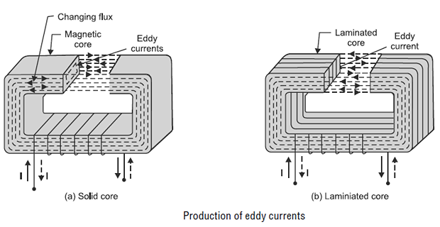
The loss is \(I^{2}R\), where \(I\) is the eddy current and \(R\) the resistance of its path. If the core is a continuous iron block of large cross-section, the magnitude of \(I\) will be very large — a big loop encircles a lot of flux, so a large EMF is induced, and it acts round a short, fat, low-resistance path. Both factors work in the wrong direction at once, and greater eddy-current loss results.
Eddy currents circulate in planes perpendicular to the flux. This geometric fact determines everything about the remedy: the laminations must be stacked so that the insulating layers cut across the eddy-current paths while leaving the flux path undisturbed. That means slicing the core in planes parallel to the flux. Laminating in the wrong plane would block the flux and leave the eddy currents untouched — a mistake that is easy to make when sketching a machine cross-section.
Lamination — the Remedy
To reduce the eddy-current loss, the obvious method is to reduce the magnitude of the eddy currents. This is achieved as follows.
Split the solid core into thin sheets, called laminations, in planes parallel to the magnetic field.
Insulate each lamination from the next by a fine layer of insulation — a varnish, an oxide film, or a phosphate coating.
This arrangement reduces the area of each section, and hence the EMF induced around any one loop.
It also increases the resistance of the eddy-current path, since the area through which the currents can pass is smaller.
The loss can be reduced further by using a magnetic material of higher resistivity, such as silicon steel.
Typical thicknesses. Power-frequency machine and transformer laminations are 0.35 mm or 0.50 mm. Aircraft equipment at 400 Hz uses 0.2 mm or thinner. Above a few kilohertz, steel of any practical thickness becomes unusable and ferrite takes over, for reasons Section 7-6 makes precise.
Laminations cannot be packed perfectly. Each carries an insulating coating, and the sheets are never perfectly flat. The stacking factor is the ratio of net iron cross-section to gross stack cross-section:
Thinner laminations mean proportionally more insulation, so \(k_s\) falls as \(t\) falls — typically 0.95 at 0.50 mm but 0.92 at 0.35 mm. The gross stack must therefore be made larger to carry the same flux, which partly offsets the saving in eddy-current loss and sets a practical floor on how thin it is worth going.
Derivation of the Loss Formula
Although it is difficult to determine the eddy-current power loss directly from the current and resistance values, experiment — and the following analysis — reveal that it can be expressed in a compact form.
Consider one lamination of thickness \(t\), width \(w\) and length \(L\), with \(w, L \gg t\), carrying a sinusoidal flux density \(B = B_m \sin\omega t\) along its length. Take an elementary loop at distance \(x\) from the centre plane, of thickness \(\mathrm{d}x\).
Step 1 — the induced EMF. The loop encloses an area \(2xL\), so
Step 2 — the path resistance. The current travels a length of about \(2L\) through a cross-section \(w\,\mathrm{d}x\):
Step 3 — the elemental power.
Step 4 — integrate across the thickness. The loops run from the centre plane out to each surface, so \(x\) goes from 0 to \(t/2\):
Finally, the volume of the lamination is \(V = Lwt\), so \(Lwt^{3} = Vt^{2}\):
where \(B_m\) is the maximum flux density in Wb/m², \(t\) the thickness of the lamination in m, \(f\) the frequency of reversal of the magnetic field in Hz, \(V\) the volume of magnetic material in m³, and \(\rho\) the resistivity in \(\Omega\)·m.
Every term of the formula now has a physical origin rather than being asserted:
\(f^{2}\) — one power from the induced EMF (\(e \propto \mathrm{d}B/\mathrm{d}t\)), and a second because power goes as \(E^{2}\).
\(B_m^{2}\) — likewise, one power from the EMF and one from squaring it.
\(t^{2}\) — one power from the reduced flux linked, one from the increased path resistance, as the insight box above explained.
\(1/\rho\) — a more resistive material simply carries less current for the same EMF. This is the second reason for adding silicon to iron: it narrows the hysteresis loop, and it raises resistivity roughly fourfold.
Problem. A transformer core of volume 0.030 m³ is built from silicon-steel laminations 0.5 mm thick, of resistivity \(50\times10^{-8}~\Omega\cdot\mathrm{m}\). It operates at 50 Hz with \(B_m = 1.4\) T. Find the eddy-current loss, in watts and in W/kg. Take the density as 7650 kg/m³.
The constant.
The loss.
Specific loss.
Comment. Compare with the hysteresis loss of Worked Example 6.4, which for a similar core came to about 2.25 W/kg. The eddy-current component is roughly a fifth of the hysteresis component here — but only because the lamination is thin. The balance between the two is entirely a design choice, set by the thickness of the sheet.
Problem. Suppose the core of Example 7.1 were made as a single solid block 60 mm thick instead of 120 laminations of 0.5 mm. Find the eddy-current loss.
Solution. Everything except \(t\) is unchanged, and \(P_e \propto t^{2}\):
Comment. One and three-quarter megawatts in thirty litres of steel. The figure is not physically attainable — long before that power was reached the flux would be expelled from the interior by the eddy currents' own field (Section 7-6), and the surface would melt. But the arithmetic makes the point with force: a solid AC core is not merely inefficient, it is impossible.
Note also what is not affected. The hysteresis loss of about 500 W would be identical in the solid block, since hysteresis depends only on material, flux density and frequency. Lamination attacks eddy currents alone.
The Complete Core-Loss Picture
With both components now derived, the total core loss can be written in full:
| Property | Hysteresis | Eddy current |
|---|---|---|
| Frequency dependence | \(\propto f\) | \(\propto f^{2}\) |
| Flux-density dependence | \(\propto B_m^{n}\), \(n \approx 1.6\text{ to }2.0\) | \(\propto B_m^{2}\) |
| Thickness dependence | None | \(\propto t^{2}\) |
| Resistivity dependence | None | \(\propto 1/\rho\) |
| Physical cause | Domain wall pinning | Induced \(I^{2}R\) in the iron |
| Reduced by | Better material, lower \(B_m\) | Thinner laminations, higher \(\rho\) |
| At constant voltage | Falls as \(f^{1-n}\) | Independent of \(f\) |
The two frequency dependences cancel exactly. So a transformer moved from a 50 Hz to a 60 Hz supply at the same voltage sees its hysteresis loss fall (Chapter 6) while its eddy-current loss stays unchanged. The total core loss therefore falls — one of the few genuinely free lunches in machine design, and worth knowing because it explains why 60 Hz equipment tolerates 50 Hz badly but not the reverse.
Separating the two by measurement. Because the frequency dependences differ, the components can be separated experimentally without dismantling anything. Divide the total by \(f\), holding \(B_m\) constant:
A plot of \(P/f\) against \(f\) is then a straight line whose intercept gives the hysteresis coefficient and whose gradient gives the eddy-current coefficient — the construction introduced in Section 6-6 and applied fully below.
Problem. Core-loss measurements on a specimen at constant \(B_m\) give 36 W at 25 Hz and 90 W at 50 Hz. Find the hysteresis and eddy-current components at 50 Hz, the frequency at which they are equal, and the predicted total loss at 60 Hz.
Step 1 — form \(P/f\).
Step 2 — solve. Subtracting,
Step 3 — the components at 50 Hz.
Check: \(54.0 + 36.0 = 90.0\) W \(\checkmark\). At 25 Hz the split is 27.0 W and 9.0 W, totalling 36.0 W \(\checkmark\)
Step 4 — the crossover. The components are equal when \(Af = Bf^{2}\):
Step 5 — prediction at 60 Hz.
Comment. Two measurements yielded a complete model. Note how the balance shifts: at 25 Hz the loss is 75 % hysteresis, at 50 Hz it is 60 %, at 75 Hz they are equal, and above that eddy currents dominate increasingly. There is nothing special about 50 Hz — it simply happens to sit below this specimen's crossover. The whole design problem at higher frequencies is that the crossover has been passed.
Problem. The specimen of Example 7.3 uses 0.50 mm laminations. A designer proposes 0.35 mm instead. Find the new eddy-current loss and total loss at 50 Hz, and comment on the stacking-factor penalty, taking \(k_s = 0.95\) at 0.50 mm and 0.92 at 0.35 mm.
New eddy-current loss. Since \(P_e \propto t^{2}\) and nothing else changes:
New total. Hysteresis is unaffected by thickness:
The stacking penalty. To carry the same flux with a lower stacking factor, the gross stack must be enlarged:
Comment. A 20 % cut in core loss for 3.3 % more stack height is a good trade, and 0.35 mm is indeed the common choice for higher-grade cores. But the returns diminish sharply: the hysteresis term is untouched no matter how thin the sheet, so the total loss can never fall below 54 W here however far the thickness is reduced. Thinning laminations attacks only one of the two losses, and once the eddy component is small the exercise stops paying. Add to that the rising cost of thin sheet, the extra handling, and the falling stacking factor, and 0.35 mm to 0.50 mm emerges as the practical optimum at power frequencies.
Skin Depth and the Frequency Limit
The derivation of Section 7-4 assumed that the flux density is uniform across the lamination. That assumption fails when the eddy currents grow large enough that their own magnetic field appreciably opposes the applied flux — which is Lenz's law acting inside the iron.
When that happens the flux is pushed towards the surface and the interior of the sheet carries little. The characteristic distance over which the field falls to \(1/e\) of its surface value is the depth of penetration or skin depth:
If \(t \ll \delta\), the flux is uniform, the \(t^{2}\) formula holds, and the iron is fully used. If \(t \gtrsim \delta\), the centre of the lamination carries almost no flux — so it contributes weight and cost but no magnetic path — and the simple formula over-predicts the loss. The practical criterion is \(t < \delta\), and comfortably so.
Note that \(\delta\) falls as \(1/\sqrt{f}\). This is the mechanism that ultimately limits how far steel can be pushed, and it explains a whole family of engineering decisions.
Problem. For silicon steel with \(\rho = 50\times10^{-8}~\Omega\cdot\mathrm{m}\) and \(\mu_r = 2000\), find the depth of penetration at 50 Hz, 400 Hz and 100 kHz. Compare each with a practical lamination thickness and comment.
Permeability.
At 50 Hz.
At 400 Hz. Scaling by \(1/\sqrt{f}\):
At 100 kHz.
| Frequency | \(\delta\) | Usable thickness | Verdict |
|---|---|---|---|
| 50 Hz | 1.13 mm | 0.35–0.50 mm | Comfortable — steel works well |
| 400 Hz | 0.40 mm | 0.20 mm | Tight — thin sheet needed |
| 100 kHz | 25 \(\mu\)m | Not manufacturable | Steel unusable — use ferrite |
Comment. At 50 Hz a 0.5 mm lamination sits comfortably inside the 1.13 mm skin depth, so the derivation of Section 7-4 is sound. At 400 Hz — the standard for aircraft and shipboard systems — the margin has largely gone, which is why such equipment uses 0.2 mm sheet. At 100 kHz the required thickness is a quarter the diameter of a human hair, and no rolling process can supply it economically.
This is the quantitative answer to the question raised in Chapter 5. Ferrite is used at high frequency not because it is a better magnetic material — it is worse on every magnetic count — but because its resistivity is around \(10^{7}\) times that of steel, which pushes the skin depth out to metres and makes eddy currents negligible in a solid block. A ferrite core needs no laminating at all.
Useful Applications of Eddy Currents
When the effects of eddy currents — the production of heat — are not utilised, the power consumed by these currents is known as eddy-current loss. But there are places where eddy currents are deliberately used to do useful work.
An iron shaft is placed as the core of an inductive coil. When a high-frequency current is passed through the coil, a large amount of heat is produced at the outermost periphery of the shaft by the eddy currents.
The amount of heat reduces considerably as one moves towards the centre of the shaft. This is because the outer periphery of the shaft offers a low-resistance path to the eddy currents — and, more fundamentally, because the skin depth of Section 7-6 confines the induced currents to a surface layer whose thickness falls as \(1/\sqrt{f}\).
The process is used for the surface hardening of heavy shafts such as automobile axles. The result is precisely what is wanted mechanically: a hard, wear-resistant skin over a tough, ductile core. Raising the frequency makes the hardened layer thinner, so the depth of hardening is set simply by the choice of supply frequency.
Eddy-current effects are used to provide damping torque in permanent-magnet moving-coil instruments. The aluminium former on which the coil is wound moves in the magnet's field; the eddy currents induced in it oppose the motion, bringing the pointer smoothly to rest without overshoot or oscillation. The damping is proportional to velocity — exactly the viscous characteristic required.
Eddy currents provide the braking torque in induction-type energy meters. A permanent magnet straddles the rotating aluminium disc; the eddy currents induced in the disc produce a retarding torque proportional to speed. Because the driving torque is proportional to power, the disc settles at a speed proportional to power, and its total revolutions measure energy.
The same principle scaled up gives a contactless brake for trains, roller coasters and dynamometers. There are no pads to wear and no fade, but the torque falls to zero at standstill, so a friction brake is still needed to hold a stationary vehicle.
A crack in a conducting component disturbs the eddy-current pattern and hence the impedance of the exciting coil. Eddy-current testing detects surface and near-surface flaws in aircraft structures and heat-exchanger tubes without dismantling anything.
A coil beneath a ceramic surface induces currents directly in a ferrous pan, heating the vessel and not the hob. Industrial induction furnaces use the same effect to melt tonnes of metal in a crucible with no contact and no combustion products.
Eddy currents induced in a buried or passing metal object react back on the search coil. The same effect, driven hard, throws non-ferrous metals sideways off a conveyor in recycling plants — an eddy-current separator.
Summary and Key Formulas
Eddy currents are circulating currents induced in the body of a conducting magnetic core by the changing flux. They do no useful work and dissipate \(I^{2}R\) heat.
Core loss = hysteresis loss + eddy-current loss, also called iron loss or magnetic loss.
A solid core is disastrous because a large loop links much flux and offers low resistance — both factors raise the loss.
Lamination in planes parallel to the flux, with insulation between sheets, reduces the EMF per loop and raises the path resistance, so the loss falls as \(t^{2}\).
The derived law is \(P_e = K_e B_m^{2}t^{2}f^{2}V\) with \(K_e = \pi^{2}/6\rho\). Higher resistivity — silicon steel — reduces it directly.
At constant voltage, hysteresis loss falls as \(f^{1-n}\) while eddy-current loss is independent of frequency, because \(f^{2}\) and \(B_m^{2} \propto 1/f^{2}\) cancel.
Plotting \(P/f\) against \(f\) gives a straight line: intercept = hysteresis, gradient = eddy. The two are equal at \(f = A/B\).
Skin depth \(\delta = \sqrt{\rho/\pi f\mu}\) must exceed the lamination thickness. It falls as \(1/\sqrt{f}\), which is why steel is unusable above a few kilohertz and ferrite takes over.
The stacking factor falls as laminations get thinner, partly offsetting the gain and setting a practical floor of about 0.35 mm at power frequencies.
Eddy currents are deliberately used in induction heating and surface hardening, instrument damping, energy-meter braking, eddy-current brakes and non-destructive testing.
| Quantity | Formula | Notes |
|---|---|---|
| Eddy-current loss | \(P_e = K_e B_m^{2} t^{2} f^{2} V\) | watts |
| Eddy constant | \(K_e = \dfrac{\pi^{2}}{6\rho}\) | \(\rho\) in \(\Omega\)·m |
| Loss per unit volume | \(\dfrac{P_e}{V} = \dfrac{\pi^{2}f^{2}B_m^{2}t^{2}}{6\rho}\) | W/m³ |
| Total core loss | \(P = k_h f B_m^{n}V + K_e f^{2}B_m^{2}t^{2}V\) | hysteresis + eddy |
| Loss separation | \(\dfrac{P}{f} = A + Bf\) | at constant \(B_m\) |
| Component split | \(P_h = Af\), \(P_e = Bf^{2}\) | from the fitted line |
| Crossover frequency | \(f = \dfrac{A}{B}\) | where the two are equal |
| Thickness scaling | \(P_e \propto t^{2}\) | hysteresis unaffected |
| Constant voltage | \(P_e\) independent of \(f\) | since \(B_m \propto 1/f\) |
| Skin depth | \(\delta = \sqrt{\dfrac{\rho}{\pi f \mu}}\) | require \(t < \delta\) |
| Stacking factor | \(k_s = \dfrac{\text{net iron area}}{\text{gross area}}\) | 0.90 to 0.97 |
| Specific loss | \(P_e/m\) in W/kg | \(m = \rho_{\text{mass}}V\) |
Common Mistakes
Believing lamination reduces hysteresis loss. It does not. Hysteresis depends on material, flux density and frequency alone; lamination attacks eddy currents only.
Laminating in the wrong plane. The sheets must lie parallel to the flux so the insulation cuts across the eddy-current paths. Slicing perpendicular to the flux would obstruct the magnetic circuit and leave the currents free.
Using \(t\) in millimetres. The formula needs metres. A 0.5 mm lamination is \(5\times10^{-4}\) m, and since the term is squared, using 0.5 instead inflates the answer by \(10^{6}\).
Assuming eddy loss rises with frequency at constant voltage. It does not change at all, because \(B_m \propto 1/f\) cancels the \(f^{2}\) exactly. Always check what is being held constant.
Confusing \(\rho\) for resistivity with \(\rho\) for density. Both appear in this chapter. Resistivity is about \(5\times10^{-7}~\Omega\)·m; density is about 7650 kg/m³.
Using \(B_{\text{rms}}\) instead of \(B_m\). Both loss formulas use the peak flux density.
Extending the \(t^{2}\) law beyond the skin depth. Once \(t \gtrsim \delta\) the flux is no longer uniform and the derivation's assumption fails.
Ignoring the stacking factor. A stack of 0.35 mm laminations is not 100 % iron. The gross dimension must be larger than the calculated net iron.
Assuming thinner is always better. Cost, handling and stacking factor all worsen, and the hysteresis floor is untouched however thin the sheet.
Forgetting that both losses are constant losses. Neither depends on load, only on supply voltage and frequency. Both continue at full value on no load.
Chapter Review
Convert thicknesses to metres before substituting — the squared term makes unit errors expensive.
P7.1 A core of volume 0.020 m³ uses 0.5 mm laminations of resistivity \(20\times10^{-8}~\Omega\cdot\mathrm{m}\). Find \(K_e\) and the eddy-current loss at 50 Hz and 1.2 T.
Show answer
\[K_e = \frac{\pi^{2}}{6\rho} = \frac{9.8696}{6\left(20\times10^{-8}\right)} = \frac{9.8696}{1.2\times10^{-6}} = 8.225\times10^{6}\]Compare with Example 7.1: this material's resistivity is 2.5 times lower, so its eddy loss is 2.5 times higher for the same conditions.\[P_e = \left(8.225\times10^{6}\right)(1.44)\left(2.5\times10^{-7}\right)(2500)(0.020) = 148.0~\mathrm{W}\]P7.2 A core has an eddy-current loss of 80 W with 0.50 mm laminations. Find the loss with 0.35 mm laminations, all else unchanged.
Show answer
A 30 % reduction in thickness gives a 51 % reduction in loss.\[P_e' = 80\left(\frac{0.35}{0.50}\right)^{2} = 80(0.49) = 39.2~\mathrm{W}\]P7.3 A core has an eddy-current loss of 40 W at 50 Hz. Find the loss at 60 Hz with \(B_m\) unchanged.
Show answer
\[P_e' = 40\left(\frac{60}{50}\right)^{2} = 40(1.44) = 57.6~\mathrm{W}\]P7.4 A transformer has a hysteresis loss of 60 W and an eddy-current loss of 30 W at 50 Hz and rated voltage. Find both at 60 Hz at the same voltage, taking \(n = 1.6\).
Show answer
At constant voltage \(B_m \propto 1/f\).
Eddy: \(P_e \propto f^{2}B_m^{2} = f^{2}(1/f)^{2}\) — constant, so 30.0 W, unchanged.
Hysteresis: \(P_h \propto f^{1-n} = f^{-0.6}\):\[P_h' = 60\left(\frac{60}{50}\right)^{-0.6} = 60(0.8964) = 53.8~\mathrm{W}\]The total core loss falls by 6.9 % — which is why 50 Hz designs run comfortably at 60 Hz.\[P_{\text{total}} = 53.8 + 30.0 = 83.8~\mathrm{W} \quad\text{against}\quad 90.0~\mathrm{W}\]P7.5 Core-loss measurements at constant \(B_m\) give 44 W at 25 Hz and 112 W at 50 Hz. Separate the components at 50 Hz.
Show answer
\[\frac{44}{25} = 1.76 = A + 25B, \qquad \frac{112}{50} = 2.24 = A + 50B\]\[0.48 = 25B \Rightarrow B = 0.01920, \qquad A = 1.76 - 0.48 = 1.280\]Check: \(64 + 48 = 112\) W \(\checkmark\). Crossover at \(f = 1.280/0.0192 = 66.7\) Hz.\[P_h = (1.280)(50) = 64.0~\mathrm{W}, \qquad P_e = (0.01920)(2500) = 48.0~\mathrm{W}\]P7.6 For the core of P7.5, predict the total loss at 40 Hz with the same \(B_m\).
Show answer
\[P_h = (1.280)(40) = 51.2~\mathrm{W}, \qquad P_e = (0.01920)(1600) = 30.7~\mathrm{W}\]\[P = 51.2 + 30.7 = 81.9~\mathrm{W}\]P7.7 Find the skin depth in a steel of resistivity \(50\times10^{-8}~\Omega\cdot\mathrm{m}\) and \(\mu_r = 1000\) at 50 Hz. Is a 0.5 mm lamination acceptable?
Show answer
\[\mu = \left(4\pi\times10^{-7}\right)(1000) = 1.2566\times10^{-3}\]Yes — 0.5 mm is comfortably below 1.59 mm, so the flux is essentially uniform and the \(t^{2}\) formula applies. Note that the lower permeability gives a larger skin depth than the \(\mu_r = 2000\) case of Example 7.5.\[\delta = \sqrt{\frac{5\times10^{-7}}{\pi(50)\left(1.2566\times10^{-3}\right)}} = \sqrt{2.533\times10^{-6}} = 1.592~\mathrm{mm}\]P7.8 A stator core stack is 200 mm high, built from 0.35 mm laminations with a stacking factor of 0.92. Find the number of laminations and the net iron height.
Show answer
\[N = \frac{200}{0.35} = 571.4 \ \to\ 571~\text{laminations}\]The missing 16 mm is insulation, coating and air gaps between imperfectly flat sheets. Flux calculations must use the net figure, not the gross stack height.\[\text{net iron} = (200)(0.92) = 184~\mathrm{mm}\]P7.9 Pure iron has a resistivity of about \(10\times10^{-8}~\Omega\cdot\mathrm{m}\); adding silicon raises it to about \(50\times10^{-8}\). By what factor does the eddy-current loss change, all else equal?
Show answer
Since \(P_e \propto 1/\rho\):The eddy-current loss falls to one-fifth. Combined with the narrower hysteresis loop of Chapter 6, this is why silicon is added despite making the alloy harder and more brittle to roll.\[\frac{P_{e,\text{Si}}}{P_{e,\text{Fe}}} = \frac{10\times10^{-8}}{50\times10^{-8}} = 0.20\]P7.10 A ferrite has a resistivity of about 10 \(\Omega\)·m against silicon steel's \(50\times10^{-8}~\Omega\cdot\mathrm{m}\). Comment on the eddy-current loss of a solid ferrite core.
Show answer
The resistivity ratio isso for the same geometry the eddy-current loss is twenty million times smaller. Equivalently, the skin depth is \(\sqrt{2\times10^{7}} \approx 4500\) times larger — metres rather than millimetres. A ferrite core therefore needs no lamination at all and is moulded as a solid block, which is exactly how ferrite cores are made. The penalty is a saturation density of about 0.4 T against steel's 2.0 T, so the core must be much larger for the same flux.\[\frac{10}{50\times10^{-8}} = 2\times10^{7}\]
MCQ 1. Eddy-current loss varies with lamination thickness as:
(a) \(t\) (b) \(t^{2}\) (c) \(t^{3}\) (d) \(1/t\)Show answer
(b) \(t^{2}\). One power from the reduced EMF, one from the increased path resistance.MCQ 2. Eddy-current loss varies with frequency as:
(a) \(f\) (b) \(f^{2}\) (c) \(\sqrt{f}\) (d) independentShow answer
(b) \(f^{2}\) at constant \(B_m\). At constant voltage it is independent of frequency — a distinction worth keeping straight.MCQ 3. Laminations are insulated from one another to:
(a) reduce hysteresis loss (b) increase the resistance of the eddy-current path (c) improve permeability (d) prevent saturationShow answer
(b) increase the resistance of the eddy-current path — and, by confining each loop to one thin sheet, reduce the EMF driving it.MCQ 4. Laminations must be stacked in planes:
(a) perpendicular to the flux (b) parallel to the flux (c) at 45° to the flux (d) it does not matterShow answer
(b) parallel to the flux, so the insulation interrupts the eddy currents without obstructing the magnetic path.MCQ 5. The constant \(K_e\) in the eddy-current formula equals:
(a) \(\pi^{2}\rho/6\) (b) \(\pi^{2}/6\rho\) (c) \(6\rho/\pi^{2}\) (d) \(\rho/\pi^{2}\)Show answer
(b) \(\pi^{2}/6\rho\). Higher resistivity gives a smaller constant and hence less loss.MCQ 6. Silicon is added to steel for cores because it:
(a) raises saturation (b) narrows the loop and raises resistivity (c) lowers cost (d) improves ductilityShow answer
(b) narrows the loop and raises resistivity — attacking both core-loss components at once. It actually lowers saturation slightly and makes the alloy more brittle.MCQ 7. Plotting core loss divided by frequency against frequency, the intercept represents:
(a) eddy-current loss (b) hysteresis loss coefficient (c) copper loss (d) total lossShow answer
(b) the hysteresis coefficient \(A = k_h B_m^{n}V\). The gradient gives the eddy-current coefficient.MCQ 8. The depth of penetration in a magnetic material varies with frequency as:
(a) \(f\) (b) \(f^{2}\) (c) \(1/\sqrt{f}\) (d) \(1/f^{2}\)Show answer
(c) \(1/\sqrt{f}\). This is why higher frequencies demand thinner laminations, and eventually ferrite.MCQ 9. Eddy currents provide the damping torque in:
(a) moving-iron instruments (b) permanent-magnet moving-coil instruments (c) electrostatic voltmeters (d) digital metersShow answer
(b) permanent-magnet moving-coil instruments, where currents induced in the aluminium former oppose the motion and bring the pointer smoothly to rest.MCQ 10. In induction surface hardening, most heat is produced at the shaft's surface because:
(a) the surface is cooler (b) eddy currents are confined to a skin depth that shrinks with frequency (c) the centre is not magnetic (d) the coil is closerShow answer
(b) eddy currents are confined to a surface layer whose thickness falls as \(1/\sqrt{f}\). Raising the frequency makes the hardened case thinner.
Explain, without algebra, why halving the lamination thickness quarters the eddy-current loss rather than halving it.
Lamination reduces eddy-current loss but not hysteresis loss. Explain why the two respond so differently to a purely geometric change.
Show that at constant applied voltage the eddy-current loss is independent of supply frequency, and explain why the same is not true of hysteresis loss.
A designer proposes reducing lamination thickness indefinitely to drive core loss towards zero. Identify three separate reasons why this fails.
Ferrite is inferior to silicon steel in permeability and in saturation density, yet it is the only choice above a few kilohertz. Explain the property that decides the matter and why it becomes dominant.
An induction motor's rotor bars carry induced currents, and so does a solid core suffering eddy-current loss. Explain what distinguishes a useful induced current from a wasteful one.
Explain why a solid iron core would not, in practice, dissipate the enormous power that the \(t^{2}\) formula predicts for it, and what would actually happen instead.
Part 1's account of the magnetic circuit is now complete. Chapters 2 to 5 established how flux is set up and what governs it; Chapters 6 and 7 have accounted in full for what it costs in heat. Every term of the "constant loss" that appears in every efficiency calculation for the rest of the book has now been derived from first principles.
Chapter 8 puts the pieces together under AC excitation, where flux, EMF and exciting current are examined as waveforms rather than steady quantities — introducing the magnetising and core-loss components of the exciting current, and the distorted, peaky waveform that saturation produces. Chapter 9 then treats permanent magnets, applying the air-gap-line construction of Chapter 5 to the demagnetisation curve. After that, Chapters 10 to 14 turn from the magnetic circuit to induction itself — Faraday's law, Lenz's law and inductance — and the machine at last begins to move.