By the end of this chapter you should be able to:
State Ohm's law and apply it in all three of its power forms.
Compute the resistance of a conductor from its dimensions and resistivity, and correct it for temperature.
Recognise open and short circuits as limiting cases of resistance.
Identify the nodes, branches and loops of a network and count the independent loops.
Apply Kirchhoff's current law at a node and Kirchhoff's voltage law around a loop, with correct signs.
Reduce series and parallel combinations to a single equivalent resistance.
Use the voltage-divider and current-divider rules without re-deriving them.
Convert between wye and delta networks to simplify circuits that have no series or parallel combinations.
Design an ammeter shunt and a voltmeter multiplier for a given movement.
Introduction
Chapter 1 gave us definitions but no relationships. We know what current and voltage mean, yet nothing so far allows us to predict the current in a circuit given the source voltage. Three statements repair that omission, and between them they are sufficient to solve every resistive DC circuit that exists.
Ohm's law relates the voltage across a single element to the current through it. Kirchhoff's current law and Kirchhoff's voltage law relate the currents and voltages of different elements according to how they are wired together. Ohm's law describes the element; Kirchhoff's laws describe the interconnection. Neither alone is enough — a circuit is elements plus topology, and you need a law for each.
Everything else in this chapter is a labour-saving consequence of those three statements. Series and parallel equivalents, the divider rules, the wye–delta transformation: each is a shortcut derived once so that you never have to write out the full set of equations for a familiar configuration again.
Ohm's Law
The flow of charge through any material meets opposition, arising from collisions between electrons and between electrons and the fixed atoms of the lattice. These collisions convert electrical energy into heat. The measure of that opposition is the resistance of the material, measured in ohms (\(\Omega\)).
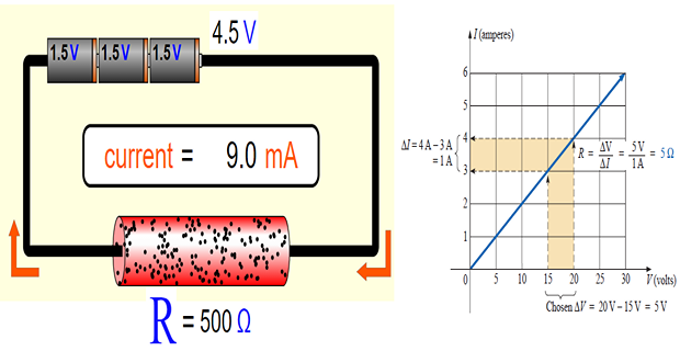
Georg Simon Ohm established experimentally that for many materials the voltage across the element is directly proportional to the current through it:
Naming the constant of proportionality the resistance \(R\) gives the law in its familiar form:
Two qualifications matter and are routinely forgotten:
The equation \(v = iR\) assumes the passive sign convention of Chapter 1. If the current reference enters the negative terminal, the correct statement is \(v = -iR\).
Ohm's law is not a law of nature in the way charge conservation is. It is a description of linear materials, and it holds only over a limited range. A diode, a filament lamp at varying temperature and a saturating iron core all violate it. An element that obeys it is called ohmic, and every resistor in this book is assumed ohmic unless stated otherwise.
It is often more convenient to work with the reciprocal of resistance, called the conductance \(G\), measured in siemens (S):
Conductance measures how well an element conducts. It is not merely notational convenience: parallel combinations add in conductance exactly as series combinations add in resistance, which is why nodal analysis in Chapter 3 is naturally written in terms of \(G\). An older unit, the mho (℧), is still occasionally encountered and is identical to the siemens.
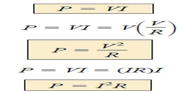
Combining \(p = vi\) from Chapter 1 with Ohm's law gives three equivalent expressions. Use whichever matches the quantities you already know:
Note that \(i^{2}R\) and \(v^{2}/R\) are both non-negative for positive \(R\). A resistor can never deliver power; it always absorbs, converting electrical energy irreversibly into heat. This is the physical meaning of the word "passive" from Chapter 1, and it is a useful sanity check: if your solution has a resistor supplying power, the solution is wrong.
Two extreme values of resistance occur so often that they have their own names and symbols.


An open switch is an open circuit; a closed switch and an ideal connecting wire are short circuits. Note the symmetry: an open circuit forces the current to zero but says nothing about its voltage, while a short circuit forces the voltage to zero but says nothing about its current. Confusing the two is the origin of a great many wrong answers.
Problem. A resistor carries 5 mA when 20 V is applied across it. Determine its resistance, its conductance, and the power it dissipates. Verify the power by all three formulas.
Solution. From Ohm's law,
Now the power, three ways:
All three agree at 100 mW, as they must. In practice you would specify a resistor rated at least 0.25 W here, since components are normally derated by a factor of two or more for reliability.
Resistivity and the Effect of Temperature
The resistance of a conductor of uniform cross-section is fixed by four things: the material, the length, the cross-sectional area, and the temperature. The first three enter through a single equation:
where \(\ell\) is the length in metres, \(A\) the cross-sectional area in square metres, and \(\rho\) the resistivity of the material in ohm-metres. The relationship is intuitive: a longer conductor offers more opportunities for collision, so \(R\) rises with \(\ell\); a thicker conductor offers more parallel paths, so \(R\) falls as \(A\) rises.
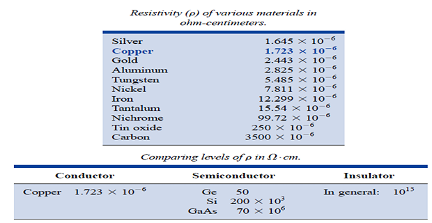
| Material | Resistivity \(\rho\) (\(\Omega\cdot\mathrm{m}\)) | Class |
|---|---|---|
| Silver | \(1.64\times10^{-8}\) | Conductor |
| Copper | \(1.72\times10^{-8}\) | Conductor |
| Aluminium | \(2.80\times10^{-8}\) | Conductor |
| Gold | \(2.45\times10^{-8}\) | Conductor |
| Carbon | \(4\times10^{-5}\) | Semiconductor |
| Silicon | \(6.4\times10^{2}\) | Semiconductor |
| Glass | \(10^{12}\) | Insulator |
| Mica | \(5\times10^{11}\) | Insulator |
Copper is the standard conductor for wiring because it combines low resistivity with mechanical workability. Aluminium, despite a higher resistivity, is used for overhead transmission lines because it is far lighter for the same current-carrying capacity. The range in this table is more than twenty orders of magnitude — nothing else in engineering spans quite so much.
Resistance also depends on temperature, and the direction of the dependence distinguishes the three classes of material:
Conductors have a positive temperature coefficient — heating increases the lattice vibration, collisions become more frequent, and resistance rises.
Semiconductors have a negative temperature coefficient — heating liberates additional charge carriers, and the increase in carrier density outweighs the increase in collisions, so resistance falls.
Insulators also have a negative temperature coefficient, for the same reason. This is why insulation failure accelerates once a cable begins to overheat.

Over normal operating temperatures the conductor characteristic is close enough to linear that a first-order correction suffices:
where \(\alpha_{1}\) is the temperature coefficient of resistance at the reference temperature \(T_{1}\), in \(^{\circ}\mathrm{C}^{-1}\). For copper at 20 °C, \(\alpha_{20} = 0.00393~^{\circ}\mathrm{C}^{-1}\); for aluminium, 0.00391. Note that \(\alpha\) is itself a function of the reference temperature, so quoting it without stating \(T_1\) is meaningless.
Problem. Calculate the resistance of 100 m of copper wire of diameter 1.6 mm at 20 °C. Take \(\rho = 1.72\times10^{-8}~\Omega\cdot\mathrm{m}\).
Solution. First the cross-sectional area, remembering to convert the diameter to metres:
Then the resistance:
Under a load current of 10 A this wire would dissipate \(i^2R = 85.5\) W and drop 8.55 V — which is why cable sizing is a design calculation, not an afterthought. The most common error in this example is forgetting to square the millimetre-to-metre conversion when computing the area.
Problem. A copper field winding measures 50 \(\Omega\) at 20 °C. What is its resistance at 80 °C? Take \(\alpha_{20} = 0.00393~^{\circ}\mathrm{C}^{-1}\).
Solution.
A rise of nearly 24 % — far from negligible. This effect is exploited deliberately in resistance thermometry, where measuring the resistance of a platinum element gives the temperature, and it must be allowed for whenever machine windings are tested cold but operate hot.
Nodes, Branches and Loops
Since circuit elements can be interconnected in many ways, we need vocabulary for the topology itself — the pattern of connections, independent of what the elements are. Three terms suffice for now; Chapter 11 develops them into a full graph-theoretic treatment.
A branch is a single two-terminal element — a resistor, a source, anything. Counting branches means counting elements.
A node is the point of connection between two or more branches. Crucially, a node includes all the wire connected to it: if two points are joined by an ideal conductor with nothing in between, they are the same node no matter how far apart they are drawn.
A loop is any closed path in the circuit that passes through no node more than once. A loop is independent if it contains at least one branch not contained in any other independent loop.
The three quantities are not independent. For any connected network,
where \(b\) is the number of branches, \(n\) the number of nodes and \(\ell\) the number of independent loops. For the network above, \(b = 5\) and \(n = 3\), giving \(\ell = 5 - 3 + 1 = 3\) independent loops. This relation is the reason nodal analysis needs \(n-1\) equations and mesh analysis needs \(b-n+1\) — a point Chapter 3 returns to when choosing between the two methods.
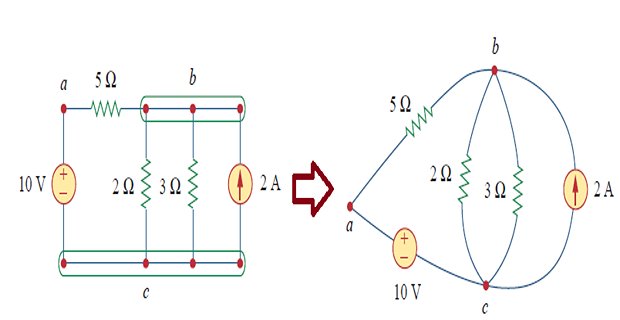
Two or more elements are in series if they exclusively share a single node and consequently carry the same current.
Two or more elements are in parallel if they are connected to the same two nodes and consequently have the same voltage across them.
The word "exclusively" in the series definition is essential. In the figure above, the 6 \(\Omega\) and 3 \(\Omega\) resistors are in parallel, since both connect node \(b\) to node \(c\). The 5 \(\Omega\) resistor is not in series with the 6 \(\Omega\), because node \(b\) is shared with two other branches, so the currents differ. Judging series and parallel by the visual appearance of the drawing rather than by the shared nodes is the most persistent error in this chapter.
Kirchhoff's Current Law
Gustav Kirchhoff's two laws, published in 1845, complete the toolkit. The first concerns nodes.
Kirchhoff's current law (KCL): the algebraic sum of the currents entering any node is zero.
where \(N\) is the number of branches meeting at the node, and currents leaving are entered with a negative sign (or vice versa — only consistency matters).
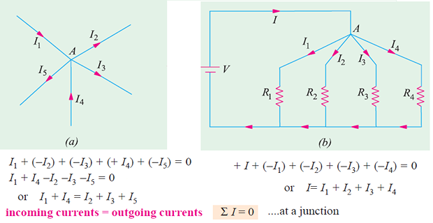
An equivalent and often more convenient statement avoids signed sums altogether:
Why it must be true. KCL is the direct consequence of conservation of charge. A node is an idealised point of zero volume; it cannot store charge. If more charge arrived than left, charge would accumulate at the node without limit, and the node voltage would rise without bound. Since neither happens, the net rate of charge arrival — which is precisely the net current — must be zero at every instant.
KCL applies not only to a single node but to any closed boundary drawn around part of a circuit, since such a region also cannot accumulate charge. This generalisation is what makes the supernode technique of Chapter 3 legitimate.
Problem. Four branches meet at a node. Currents of 10 A and 3 A enter the node, and a current of 5 A leaves it. Determine the fourth current \(i_{4}\) and state its direction.
Solution. Take currents entering as positive and let \(i_4\) be assumed leaving:
The result is positive, so 8 A does indeed leave the node, as assumed. Had the answer come out negative, the magnitude would still be correct and the true direction would simply be into the node — the assumed reference direction never affects the physics, only the sign of the answer.
Kirchhoff's Voltage Law
The second law concerns loops.
Kirchhoff's voltage law (KVL): the algebraic sum of all voltages around a closed path is zero.
where \(M\) is the number of elements in the loop.
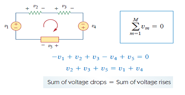
Why it must be true. KVL follows from conservation of energy. Voltage is energy per unit charge, so carrying a test charge once around a closed loop and returning it to its starting point must involve zero net energy transfer — otherwise energy could be created by circulating charge indefinitely. The potential at a point is single-valued, and a closed path returns to that same value.
The sign rule. Choose a direction of travel around the loop, either clockwise or anticlockwise; it makes no difference provided you keep it. Then, for each element you traverse:
Enter at the \(-\) terminal and leave at the \(+\) terminal: the voltage is a rise, entered as \(-v\) in the sum (or \(+v\) if you are summing rises).
Enter at the \(+\) terminal and leave at the \(-\) terminal: the voltage is a drop, entered as \(+v\).
Whichever convention you adopt, apply it to every element in the loop without exception. Almost all KVL errors are sign errors, and almost all sign errors come from switching convention halfway round.
Problem. A single loop contains a 24 V source, a 4 \(\Omega\) resistor, a 6 V source opposing the first, and a 2 \(\Omega\) resistor. Find the loop current and verify conservation of power.
Solution. Assume a clockwise current \(i\) and travel clockwise, entering drops as positive. The 24 V source is traversed from \(-\) to \(+\) (a rise), the 6 V source from \(+\) to \(-\) (a drop):
The resistor voltages follow from Ohm's law:
Power check. The 24 V source drives current out of its positive terminal, so it supplies; the 6 V source is being driven backwards, so it absorbs:
This is exactly what happens when a battery charger works: the smaller source absorbs energy from the larger one. Note that the check caught nothing here because the solution was right — but it costs thirty seconds and would have caught a sign error immediately.
Series Resistors and Voltage Division
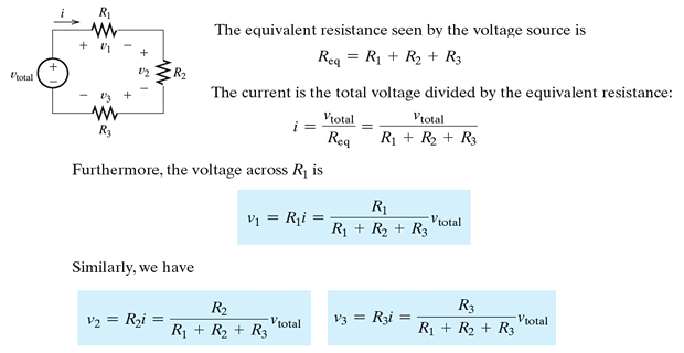
Consider \(N\) resistors connected end to end so that the same current \(i\) flows through all of them. By Ohm's law, the voltage across each is
Applying KVL around the loop, the applied voltage equals the sum of the individual drops:
The combination therefore behaves exactly as a single resistor of value
The equivalent resistance of series resistors is the sum of the individual resistances, and is therefore always larger than the largest of them.
Since \(i = v/R_{\mathrm{eq}}\) is common to every element, the voltage across the \(k\)th resistor is
In words: the applied voltage divides among series resistors in direct proportion to their resistances. The largest resistor takes the largest share. For the common two-resistor case,
Problem. Resistors of 2 \(\Omega\), 4 \(\Omega\) and 6 \(\Omega\) are connected in series across a 12 V source. Find the current, the voltage across each resistor, and confirm the last by the divider rule.
Solution.
By the divider rule, without computing the current at all:
KVL confirms the total: \(2 + 4 + 6 = 12\) V. Observe that the 6 \(\Omega\) resistor, being half the total resistance, takes half the supply voltage.
Parallel Resistors and Current Division
Now consider \(N\) resistors connected between the same pair of nodes, so that the same voltage \(v\) appears across all of them. By Ohm's law,
Applying KCL at the upper node:
so that
In terms of conductance this is far tidier, and shows the exact duality with the series case:
Conductances in parallel add exactly as resistances in series do. The equivalent resistance of a parallel combination is always smaller than the smallest resistor in it — adding another path can only make it easier for current to flow.
For exactly two resistors in parallel the reciprocal formula simplifies to the product-over-sum rule:
This holds for two resistors only. Attempting to extend it to three by writing \(R_1R_2R_3/(R_1+R_2+R_3)\) is wrong, and is one of the most frequently repeated errors in the subject. For three or more, either use the reciprocal formula or apply product-over-sum twice.
A useful special case worth memorising: \(N\) equal resistors of value \(R\) in parallel give \(R_{\mathrm{eq}} = R/N\).
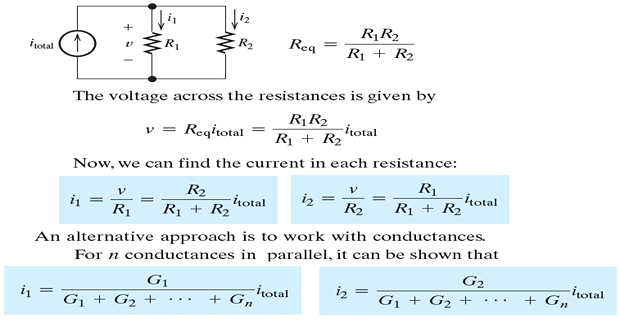
With \(v = i R_{\mathrm{eq}}\) common to all branches, the current in the \(k\)th branch is
The total current divides among parallel branches in direct proportion to their conductances — equivalently, in inverse proportion to their resistances. For two resistors this becomes the form you will use most often:
Note the crossover carefully: the current in \(R_1\) is proportional to \(R_2\), the other resistance. This is the opposite of the voltage divider, where \(v_1\) is proportional to \(R_1\) itself. Writing the current divider with the same resistance on top as the voltage divider is an extremely common slip. A quick sanity check settles it every time: the smaller resistor must carry the larger current.
Problem. A 12 A source feeds a parallel combination of 4 \(\Omega\) and 12 \(\Omega\). Find the equivalent resistance, the voltage across the combination, and the current in each branch.
Solution.
Note that 3 \(\Omega\) is less than the smaller of the two, as it must be.
By the current-divider rule, with the other resistance in the numerator:
Check by Ohm's law: \(36/4 = 9\) A and \(36/12 = 3\) A. KCL confirms \(9 + 3 = 12\) A. The 4 \(\Omega\) branch, being three times more conductive, carries three times the current — exactly as the sanity check predicts.
Problem. A 30 V source is connected through a 4 \(\Omega\) series resistor to a parallel combination of 6 \(\Omega\) and 12 \(\Omega\). Find the source current, the voltage across the parallel section, the branch currents, and verify the power balance.
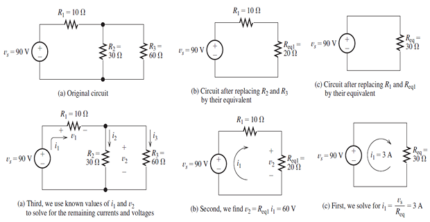
Solution. Work from the end farthest from the source. First collapse the parallel pair:
This is now in series with the 4 \(\Omega\):
Now work backwards to recover the internal quantities. The voltage across the parallel section is
KCL check: \(2.5 + 1.25 = 3.75\) A \(\checkmark\). Power check:
This is the standard procedure for any ladder network: collapse inward from the far end to find the source current, then expand back outward to recover every internal voltage and current. Chapter 3 provides methods that do not require the circuit to reduce this way — but when it does reduce, this is the fastest route.
Wye–Delta Transformations
Series and parallel reduction is powerful, but it fails whenever the network contains a bridge — a configuration in which no two resistors are either in series or in parallel. The Wheatstone bridge is the classic instance. For these cases we need a transformation that exchanges one three-terminal configuration for an equivalent one.
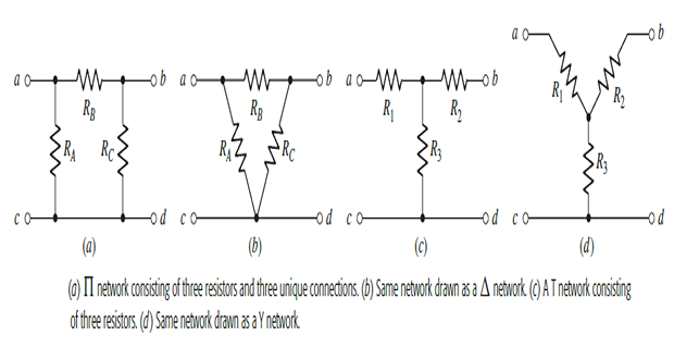
Two such configurations exist. The wye (Y) or star (T) network has three resistors meeting at a common internal node. The delta (Δ) or pi (Π) network has three resistors forming a closed triangle. Both present three terminals to the outside world, and for any Y there is a Δ that is indistinguishable from it at those terminals — and vice versa.
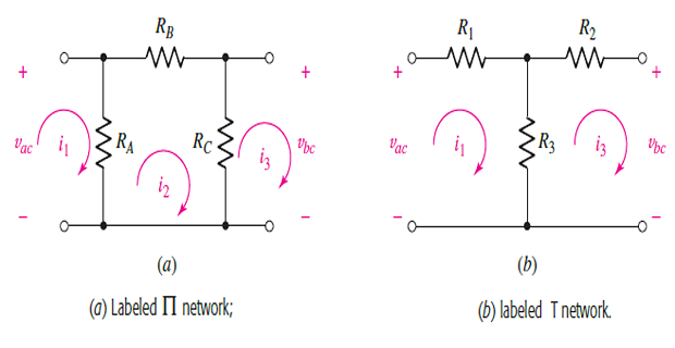
Equivalence means that the resistance measured between any pair of terminals must be the same for both networks, with the third terminal left open. For terminals \(a\) and \(b\), the wye gives simply \(R_1 + R_2\), while in the delta \(R_c\) is in parallel with the series pair \(R_a + R_b\):
Repeating for the other two terminal pairs:
Three equations in three unknowns. Adding all three and halving gives \(R_1+R_2+R_3\), and subtracting each original equation in turn isolates the individual resistances.
Memory rule. Each resistor of the wye is the product of the two adjacent delta resistors divided by the sum of all three. "Adjacent" means the two delta branches that meet at the corresponding terminal.
Memory rule. Each resistor of the delta is the sum of the pairwise products of the wye resistances divided by the opposite wye resistor. The numerator is the same in all three expressions, so compute it once.
A pleasing special case: if the network is balanced, with all three wye resistors equal to \(R_Y\) and all three delta resistors equal to \(R_\Delta\), both formulas collapse to
This single relation reappears throughout Chapter 12 on three-phase circuits, where balanced wye and delta loads are the norm rather than the exception.
Problem. Convert the delta network with \(R_{a} = 30~\Omega\), \(R_{b} = 20~\Omega\) and \(R_{c} = 10~\Omega\) into its equivalent wye. Then convert back as a check.
Solution. The sum appears in every denominator, so compute it once:
Check by converting back. The common numerator is
The original delta is recovered exactly. Note the pattern: the largest delta resistor \(R_a = 30\) converts to the largest wye resistor \(R_3 = 10\) at the opposite position. Getting the correspondence backwards is the usual failure mode, which is why the labelled figure above is worth consulting every time until the pattern is automatic.
Practical Engineering Applications
Household lamps are wired in parallel, and the reason is a direct consequence of this chapter. In a parallel arrangement every lamp receives the full supply voltage, so each operates at its designed brightness independently of the others, and the failure of one leaves the rest unaffected — an open circuit in one branch removes only that branch.
In a series arrangement the supply voltage divides between the lamps, so each receives only a fraction and all dim as more are added. Worse, a single failed lamp opens the circuit and extinguishes every lamp in the string — the notorious behaviour of older decorative light chains. The trade-off is cost: series strings need far less wiring, which is why they persisted for decorative use long after parallel wiring became standard elsewhere.
The moving-coil (d'Arsonval) movement is the heart of the classical analogue meter. It is characterised by two numbers: the current \(I_{fs}\) that produces full-scale deflection, and the coil resistance \(R_{m}\). A typical movement might have \(I_{fs} = 1\) mA and \(R_m = 100~\Omega\). On its own that is a 1 mA ammeter and nothing else. Series and parallel resistors turn it into an instrument of any range you please.
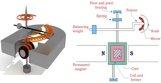
Ammeter — the shunt. To measure currents larger than \(I_{fs}\), place a low-value shunt resistor \(R_{n}\) in parallel with the movement so that most of the current bypasses the coil. By current division, the movement must receive exactly \(I_{fs}\) when the total is the desired full-scale current \(I\):

Voltmeter — the multiplier. To measure voltage, place a large multiplier resistor \(R_{n}\) in series with the movement, so that the desired full-scale voltage \(V\) drives exactly \(I_{fs}\) through the combination:

The loading effect. An ideal ammeter would have zero resistance and an ideal voltmeter infinite resistance, so that inserting either changes nothing. Real meters do neither, and inserting them perturbs the circuit they measure. This is why a voltmeter is specified by its sensitivity in ohms per volt — a figure that is simply \(1/I_{fs}\), and for our 1 mA movement equals 1000 \(\Omega\)/V.
Problem. A movement has \(I_{fs} = 1~\mathrm{mA}\) and \(R_{m} = 100~\Omega\). Design (a) a 0–1 A ammeter and (b) a 0–100 V voltmeter.
Solution (a). Shunt resistance:
A shunt of about 100 m\(\Omega\) — very low, as expected, since it must carry 999 times the movement current. Such shunts are made from manganin strip, chosen for its near-zero temperature coefficient so that the calibration does not drift as the shunt self-heats.
Solution (b). Multiplier resistance:
Note that the movement resistance is almost negligible here — omitting it would give 100 k\(\Omega\), an error of only 0.1 %. For a low-voltage range, however, the correction matters a great deal, so it should never be dropped as a matter of habit.
Summary and Key Formulas
Ohm's law, \(v = iR\), holds for linear (ohmic) elements under the passive sign convention. Conductance is its reciprocal, \(G = 1/R\), in siemens.
Resistance is \(R = \rho\ell/A\) and varies with temperature; conductors have a positive temperature coefficient, semiconductors and insulators a negative one.
An open circuit has \(R\to\infty\) and carries no current; a short circuit has \(R\to 0\) and sustains no voltage.
A resistor always absorbs power, given by \(p = vi = i^{2}R = v^{2}/R\).
Branches, nodes and independent loops satisfy \(b = \ell + n - 1\).
KCL — the algebraic sum of currents at a node is zero — follows from conservation of charge and extends to any closed boundary.
KVL — the algebraic sum of voltages around a loop is zero — follows from conservation of energy.
Series resistances add; the voltage divides in proportion to resistance. Parallel conductances add; the current divides in proportion to conductance.
The wye–delta transformation handles networks with no series or parallel combinations. For balanced networks, \(R_{\Delta} = 3R_{Y}\).
| Result | Formula | Conditions |
|---|---|---|
| Ohm's law | \(v = iR\) | linear element, passive sign convention |
| Conductance | \(G = 1/R\) | unit: siemens (S) |
| Resistance of a conductor | \(R = \rho\ell/A\) | uniform cross-section |
| Temperature correction | \(R_2 = R_1[1+\alpha_1(T_2-T_1)]\) | \(\alpha_1\) quoted at \(T_1\) |
| Resistive power | \(p = i^{2}R = v^{2}/R\) | always positive |
| Topology relation | \(b = \ell + n - 1\) | connected network |
| KCL | \(\sum i_k = 0\) | at any node or closed boundary |
| KVL | \(\sum v_k = 0\) | around any closed loop |
| Series equivalent | \(R_{\mathrm{eq}} = \sum R_k\) | same current in all |
| Parallel equivalent | \(1/R_{\mathrm{eq}} = \sum 1/R_k\) | same voltage across all |
| Two in parallel | \(R_{\mathrm{eq}} = \dfrac{R_1R_2}{R_1+R_2}\) | two resistors only |
| Voltage divider | \(v_k = \dfrac{R_k}{\sum R}\,v\) | series; own resistance on top |
| Current divider (two) | \(i_1 = \dfrac{R_2}{R_1+R_2}\,i\) | parallel; other resistance on top |
| Delta to wye | \(R_1 = \dfrac{R_bR_c}{R_a+R_b+R_c}\) | adjacent product over total sum |
| Wye to delta | \(R_a = \dfrac{R_1R_2+R_2R_3+R_3R_1}{R_1}\) | pairwise sum over opposite |
| Balanced case | \(R_\Delta = 3R_Y\) | all three equal |
| Ammeter shunt | \(R_n = \dfrac{I_{fs}}{I-I_{fs}}R_m\) | shunt in parallel with movement |
| Voltmeter multiplier | \(R_n = \dfrac{V}{I_{fs}} - R_m\) | multiplier in series |
Common Mistakes
Extending product-over-sum to three resistors. \(R_1R_2R_3/(R_1+R_2+R_3)\) is not the parallel equivalent of three resistors. Use the reciprocal formula, or apply product-over-sum twice.
Swapping the numerator in the current-divider rule. For two parallel resistors, the current in \(R_1\) is proportional to \(R_2\). Check: the smaller resistor must carry the larger current.
Judging series and parallel by appearance. Two resistors drawn end to end are in series only if no other branch connects at the shared node. Trace the nodes, do not trust the drawing.
Forgetting to square the unit conversion for area. A diameter of 1.6 mm gives an area in \(\mathrm{m^2}\) only if the millimetres are converted before squaring.
Changing sign convention halfway round a KVL loop. Pick "drops positive" or "rises positive", and apply it to every element without exception.
Assuming a resistor can supply power. If your solution has \(p \lt 0\) for a resistor, there is a sign error upstream.
Treating the wye–delta correspondence loosely. \(R_a\) lies opposite terminal \(a\); \(R_1\) connects to terminal \(a\). Mixing the two produces answers that look plausible and are wrong.
Applying Ohm's law to a non-ohmic element. Diodes, lamps at varying temperature and saturating cores are not linear. The ratio \(v/i\) still has units of ohms but is not a constant.
Confusing open and short circuits. Open forces \(i = 0\) and leaves \(v\) free; short forces \(v = 0\) and leaves \(i\) free.
Omitting \(R_m\) when designing a voltmeter multiplier. Negligible on a 100 V range, but a serious error on a 1 V range.
Chapter Review
Work these before opening the answers. Quote results to four significant figures with correct units, and use the power balance as a check wherever a full circuit is solved.
P2.1 A 10 k\(\Omega\) resistor carries 2 mA. Find the voltage across it and the power dissipated.
Show answer
\[v = iR = (2\times10^{-3})(10^{4}) = 20~\mathrm{V}, \qquad p = i^{2}R = (2\times10^{-3})^{2}(10^{4}) = 40~\mathrm{mW}\]P2.2 Find the conductance of a 250 \(\Omega\) resistor.
Show answer
\[G = \frac{1}{250} = 4\times10^{-3}~\mathrm{S} = 4~\mathrm{mS}\]P2.3 An aluminium conductor is 50 m long with a cross-section of 1.5 mm\(^{2}\). Find its resistance, taking \(\rho = 2.8\times10^{-8}~\Omega\cdot\mathrm{m}\).
Show answer
\[A = 1.5~\mathrm{mm^{2}} = 1.5\times10^{-6}~\mathrm{m^{2}}\]\[R = \frac{(2.8\times10^{-8})(50)}{1.5\times10^{-6}} = \frac{1.4\times10^{-6}}{1.5\times10^{-6}} = 0.9333~\Omega\]P2.4 Three branches meet at a node. A current of 8 A enters and 6 A leaves. Find the third current and its direction.
Show answer
\[8 = 6 + i_{3} \quad\Longrightarrow\quad i_{3} = 2~\mathrm{A}\ \text{leaving the node}\]P2.5 Resistors of 5 \(\Omega\), 10 \(\Omega\) and 15 \(\Omega\) are in series across 60 V. Find the current and the voltage across the 10 \(\Omega\).
Show answer
\[R_{\mathrm{eq}} = 30~\Omega, \qquad i = \frac{60}{30} = 2~\mathrm{A}\]\[v_{10} = \frac{10}{30}(60) = 20~\mathrm{V}\]P2.6 A total current of 5 A divides between parallel resistors of 20 \(\Omega\) and 30 \(\Omega\). Find \(R_{\mathrm{eq}}\), the common voltage, and each branch current.
Show answer
\[R_{\mathrm{eq}} = \frac{(20)(30)}{50} = 12~\Omega, \qquad v = (5)(12) = 60~\mathrm{V}\]Check: \(60/20 = 3\) A and \(60/30 = 2\) A, summing to 5 A.\[i_{20} = \frac{30}{50}(5) = 3~\mathrm{A}, \qquad i_{30} = \frac{20}{50}(5) = 2~\mathrm{A}\]P2.7 Convert a balanced delta of three 12 \(\Omega\) resistors to its equivalent wye.
Show answer
Consistent with \(R_{\Delta} = 3R_{Y}\), since \(3\times4 = 12\).\[R_{Y} = \frac{(12)(12)}{12+12+12} = \frac{144}{36} = 4~\Omega \ \text{in each leg}\]P2.8 Convert a balanced wye of three 6 \(\Omega\) resistors to its equivalent delta.
Show answer
Again \(R_{\Delta} = 3R_{Y} = 18~\Omega\).\[R_{\Delta} = \frac{(36)+(36)+(36)}{6} = \frac{108}{6} = 18~\Omega \ \text{in each branch}\]P2.9 Design a voltage divider to obtain 9 V from a 24 V supply, using a total resistance of 8 k\(\Omega\). Assume no load is connected.
Show answer
\[9 = \frac{R_{2}}{8000}(24) \quad\Longrightarrow\quad R_{2} = \frac{9 \times 8000}{24} = 3000~\Omega = 3~\mathrm{k}\Omega\]Connecting any real load across \(R_2\) will pull the output below 9 V — the divider must be designed with the load in place.\[R_{1} = 8000 - 3000 = 5~\mathrm{k}\Omega\]P2.10 An incandescent lamp is rated 100 W at 240 V. Find its hot resistance and operating current.
Show answer
\[R = \frac{v^{2}}{p} = \frac{240^{2}}{100} = \frac{57600}{100} = 576~\Omega\]Its cold resistance is roughly ten times smaller, which is why filament lamps fail at switch-on — the inrush current is large.\[i = \frac{p}{v} = \frac{100}{240} = 0.4167~\mathrm{A}\]
MCQ 1. Ohm's law in the form \(v = iR\) is valid for:
(a) all circuit elements (b) linear resistors only (c) sources only (d) capacitors and inductorsShow answer
(b) linear resistors only. Diodes and saturating elements are non-ohmic; capacitors and inductors obey differential relations instead.MCQ 2. The SI unit of conductance is the:
(a) ohm (b) siemens (c) henry (d) faradShow answer
(b) siemens. The older name, the mho, means the same thing.MCQ 3. Elements connected in series necessarily share the same:
(a) voltage (b) current (c) power (d) resistanceShow answer
(b) current. Parallel elements share the same voltage — the dual statement.MCQ 4. Kirchhoff's current law is a consequence of the conservation of:
(a) energy (b) charge (c) momentum (d) powerShow answer
(b) charge. KVL is the one that follows from conservation of energy.MCQ 5. Two 6 \(\Omega\) resistors in parallel are equivalent to:
(a) 12 \(\Omega\) (b) 6 \(\Omega\) (c) 3 \(\Omega\) (d) 1.5 \(\Omega\)Show answer
(c) 3 \(\Omega\). For \(N\) equal resistors in parallel, \(R_{\mathrm{eq}} = R/N\).MCQ 6. For a short circuit:
(a) \(v = 0\), \(i\) arbitrary (b) \(i = 0\), \(v\) arbitrary (c) both zero (d) both infiniteShow answer
(a). \(R\to0\) forces the voltage to zero but places no restriction on the current. Option (b) describes an open circuit.MCQ 7. A network has 8 branches and 5 nodes. The number of independent loops is:
(a) 3 (b) 4 (c) 12 (d) 13Show answer
(b) 4. From \(b = \ell + n - 1\), \(\ell = 8 - 5 + 1 = 4\).MCQ 8. A balanced delta of three 9 \(\Omega\) resistors converts to a wye with each leg equal to:
(a) 27 \(\Omega\) (b) 9 \(\Omega\) (c) 3 \(\Omega\) (d) 1 \(\Omega\)Show answer
(c) 3 \(\Omega\). Since \(R_\Delta = 3R_Y\), we get \(R_Y = 9/3 = 3~\Omega\).MCQ 9. A 12 V supply is applied across series resistors of 2 k\(\Omega\) and 4 k\(\Omega\). The voltage across the 4 k\(\Omega\) is:
(a) 4 V (b) 6 V (c) 8 V (d) 12 VShow answer
(c) 8 V. \(v = \frac{4}{2+4}(12) = 8~\mathrm{V}\). The larger resistor takes the larger share.MCQ 10. The temperature coefficient of resistance is negative for:
(a) copper (b) aluminium (c) silver (d) siliconShow answer
(d) silicon. Semiconductors and insulators have negative coefficients; all three metals listed have positive ones.
Ohm's law is called a law, yet it is routinely violated by real devices. In what sense is it a law at all, and how does its status differ from that of Kirchhoff's laws?
Two resistors are drawn one directly above the other on a diagram, connected at both ends by wire. Are they necessarily in parallel? What would have to be true for them not to be?
Explain why the equivalent resistance of a parallel combination must be smaller than the smallest resistor in it, without using the formula.
KCL is usually stated for a node. Explain why it applies equally to a closed surface enclosing several nodes, and give a circuit in which that generalisation saves work.
A voltage divider is designed to deliver 9 V from a 24 V supply. A load is then connected across the output and the voltage falls. Explain why, and describe two ways to reduce the effect.
Why can a wye–delta transformation solve a bridge circuit when series–parallel reduction cannot? What is it about a bridge that defeats the simpler method?
You can now solve any resistive circuit in principle — write KCL at every node, KVL around every loop, apply Ohm's law to every resistor, and solve the resulting system. In practice that produces far more equations than necessary, and for a circuit of any size it becomes unmanageable.
Chapter 3 fixes this. Nodal analysis uses KCL together with node voltages to produce exactly \(n-1\) equations, and mesh analysis uses KVL together with mesh currents to produce exactly \(b-n+1\) — the two numbers that appeared in the topology relation of Section 2.4. Neither introduces any new physics. They are simply the most economical way of organising the laws you already have.