- Explain the advantages of a three-phase system over a single-phase one for the same power.
- Write balanced three-phase voltages and identify the phase sequence as abc or acb.
- Relate line and phase quantities for both Y and Δ connections, including the 30° angle.
- Analyse all four source–load combinations by the per-phase method.
- Convert between \(\mathbf{Z}_{Y}\) and \(\mathbf{Z}_{\Delta}\) for balanced loads.
- Show that the total instantaneous power in a balanced system is constant, and compute \(P\), \(Q\) and \(S\).
- Quantify the conductor material saved by three-phase transmission.
- Analyse an unbalanced system by mesh or nodal analysis, and find the neutral current.
- Apply the two-wattmeter method to obtain total power, reactive power and power factor.
Introduction and Advantages
Every circuit so far has had a single source, or several sources all at the same phase. A polyphase system is one in which the AC sources operate at the same frequency but at different phases. By far the most important is the three-phase system, in which three sources of equal magnitude are displaced by 120°.
Virtually all the electric power on Earth is generated, transmitted and distributed in three-phase form. The reasons are worth setting out, because they are not obvious and they are not merely conventional.
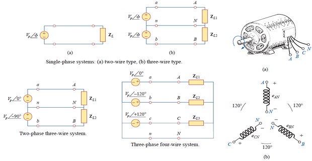
The advantages, for the same delivered power:
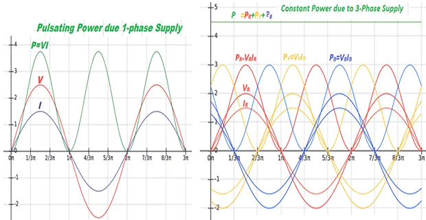
Constant instantaneous power. The total power delivered to a balanced three-phase load does not fluctuate at all, whereas single-phase power pulsates at \(2\omega\) between zero and twice its average. A three-phase motor therefore produces steady torque; a single-phase motor vibrates. Section 12.7 proves this.
Less conductor material. Three-phase transmission requires about 25 % less copper or aluminium than single-phase for the same power and the same losses — equivalently, single-phase needs 33 % more. Section 12.8 derives the figure.
Better generation. A three-phase alternator has a higher power-to-weight ratio, so it is smaller, lighter and cheaper for a given output, and easier to transport and install.
Self-starting motors. Three-phase currents in three windings produce a rotating magnetic field, so a three-phase induction motor starts by itself. A single-phase motor produces only a pulsating field and needs auxiliary starting arrangements — a capacitor, a shaded pole, or a starting winding — which add cost and reduce reliability.
Better power factor in three-phase machines, and greater reliability under fault conditions, since a fault on one phase need not interrupt the others.
Compatibility. A three-phase supply can feed a single-phase load simply by taking one phase and neutral. The converse is not possible.
Balanced Three-Phase Voltages
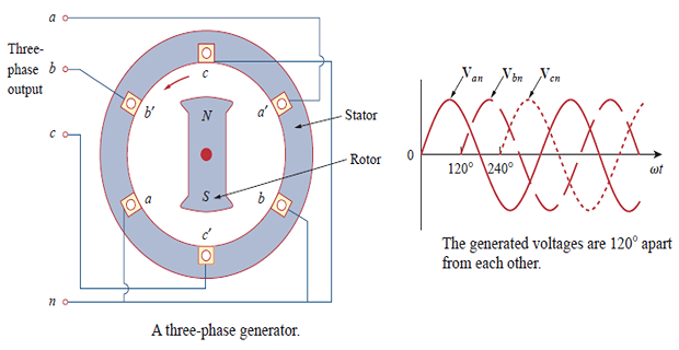
Three-phase voltages are produced by an alternator whose rotor carries a magnet and whose stator carries three coils \(a\text{-}a'\), \(b\text{-}b'\) and \(c\text{-}c'\) placed physically 120° apart. As the rotor turns, its field cuts each coil in succession, inducing three voltages equal in magnitude but displaced in time by one third of a cycle.
Balanced phase voltages are equal in magnitude and 120° out of phase with one another. The two conditions together are what "balanced" means:
The second condition follows from the first plus the 120° spacing, and it is the fact that makes everything in this chapter work.
The phase sequence is the time order in which the voltages reach their respective maxima. There are only two possibilities, determined by the direction of rotor rotation.
abc or positive sequence — produced by anticlockwise rotation:
acb or negative sequence — produced by clockwise rotation:
Either way the three sum to zero, which is easily verified in rectangular form:
Phase sequence matters practically. It determines the direction in which a three-phase motor turns. Interchanging any two of the three supply leads reverses the sequence and hence reverses the motor — which is both the standard way to reverse a machine and a classic commissioning error when a pump or conveyor is found running backwards.
This book assumes the abc sequence throughout unless stated otherwise.
Balanced Loads and Connections
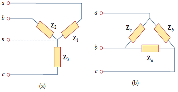
A balanced load is one whose phase impedances are equal in magnitude and in phase angle. For a Y-connected load and a Δ-connected load respectively:
The wye–delta transformation of Section 2.9, applied to three equal impedances, gives the conversion that will be used constantly:
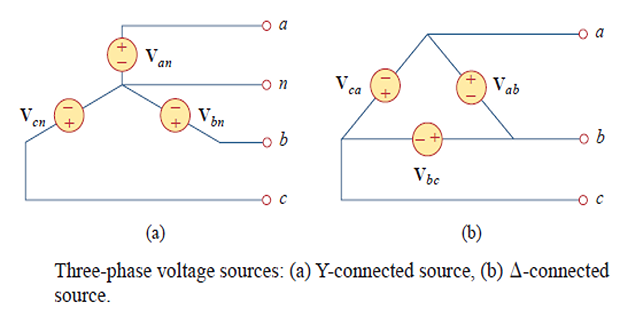
Both the source and the load may be connected in either Y or Δ, giving four combinations: Y–Y, Y–Δ, Δ–Δ and Δ–Y. All four are analysed in the sections that follow, and all four reduce to the same per-phase calculation.
One practical note: a Δ-connected source is rare, because any small imbalance in the three generated voltages produces a large circulating current around the closed delta loop, with nothing to limit it but the winding impedance. Sources are almost always Y-connected. Loads are commonly either.
Balanced Y–Y Connection
Take a Y-connected source feeding a Y-connected load, with the neutrals joined. This is the fundamental case; the other three reduce to it.

Line voltages. The phase voltages \(\mathbf{V}_{an}\), \(\mathbf{V}_{bn}\), \(\mathbf{V}_{cn}\) are measured from each line to the neutral. The line voltages are measured between lines, and follow by subtraction:
and similarly
Two facts, both essential: the line voltage magnitude is \(\sqrt{3}\) times the phase voltage, and the line voltages lead their corresponding phase voltages by 30°. The factor \(\sqrt{3} = 1.732\) is why a 400 V three-phase supply gives 230 V between any line and neutral, and both figures appear on the same distribution board.
Line currents. Each phase of the load sees its own phase voltage, so
In a Y connection the line current is the phase current, since the same conductor carries both:
The neutral carries nothing. Summing the three line currents:
The two neutral points are at the same potential regardless of the neutral wire's impedance, so the neutral wire can be removed entirely without changing anything. This is why three-phase transmission uses three conductors rather than four, and it is the single largest source of the material saving computed in Section 12.8. Note carefully that this holds only for a balanced load; Section 12.9 shows what happens otherwise.
Since the three phases are identical apart from a 120° rotation, there is no need to solve all three. Solve one, then rotate:
This is the per-phase equivalent circuit: a single-phase circuit consisting of one source \(\mathbf{V}_{an}\) and one impedance \(\mathbf{Z}_{Y}\) with a return through the neutral. Every three-phase problem in this chapter is solved this way, and the whole apparatus of Chapters 9 to 11 applies to it directly.

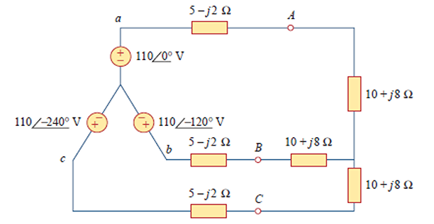
Problem. A balanced Y-connected source with \(\mathbf{V}_{an} = 110\angle 0^{\circ}~\mathrm{V}\), abc sequence, feeds a Y-connected load of \(\left(10+j8\right)~\Omega\) per phase through a line impedance of \(\left(5-j2\right)~\Omega\) per phase. Find the line currents.
Solution. Line and load impedances are in series in each phase:
Solve one phase:
and rotate for the other two:
Three phases solved with one division. Note that the angles are simply \(-21.80^{\circ}\) shifted by \(\mp120^{\circ}\), and the magnitudes are identical — the definition of balance.
Balanced Y–Δ Connection
Now a Y-connected source feeds a Δ-connected load. The load has no neutral point, so each phase of the load sees a line voltage:
The phase currents in the load follow directly:
Line currents. In a delta the line current is not the phase current; each line carries the difference of two phase currents. Applying KCL at node \(A\):
So the roles are exactly reversed from the Y connection. There, \(V_{L} = \sqrt{3}V_{p}\) and \(I_{L} = I_{p}\); here, \(V_{L} = V_{p}\) and \(I_{L} = \sqrt{3}I_{p}\). And where the line voltage led by 30° in the Y case, the line current lags by 30° in the Δ case.
| Connection | Voltage | Current | 30° relationship |
|---|---|---|---|
| Y (star) | \(V_{L} = \sqrt{3}V_{p}\) | \(I_{L} = I_{p}\) | line voltage leads phase voltage by 30° |
| Δ (delta) | \(V_{L} = V_{p}\) | \(I_{L} = \sqrt{3}I_{p}\) | line current lags phase current by 30° |
This table is the single most useful thing to memorise in the chapter. A reliable mnemonic: the \(\sqrt{3}\) always goes with the quantity that is not shared. In a Y the three phases share the line conductors, so the currents match and the voltages differ; in a Δ the phases share the line terminals, so the voltages match and the currents differ.
Problem. A balanced abc-sequence Y-connected source with \(\mathbf{V}_{an} = 100\angle 10^{\circ}~\mathrm{V}\) feeds a Δ-connected balanced load of \(\left(8+j4\right)~\Omega\) per phase. Calculate the phase and line currents.
Method 1 — work through the delta.
The load sees the line voltage, which leads \(\mathbf{V}_{an}\) by 30° and is \(\sqrt{3}\) times larger:
and the line current lags the phase current by 30°:
Method 2 — convert the load to Y. Much quicker if only the line currents are wanted:
One division instead of three steps. Method 2 is almost always the better route: convert any Δ load to its Y equivalent using \(\mathbf{Z}_{Y} = \mathbf{Z}_{\Delta}/3\), then analyse per-phase. Only revert to Method 1 when the phase currents inside the delta are specifically required — for instance to size the load's own conductors.
Balanced Δ–Δ and Δ–Y Connections
With both source and load in delta, the source phase voltages are the line voltages, and they are applied directly across the load phases:
and the line currents follow by KCL at each corner:
giving \(I_{L} = \sqrt{3}I_{p}\) as before, with each line current lagging its corresponding phase current by 30°.
Problem. A balanced Δ-connected load of \(\left(20-j15\right)~\Omega\) per phase is fed by a Δ-connected positive-sequence generator with \(\mathbf{V}_{ab} = 330\angle 0^{\circ}~\mathrm{V}\). Calculate the phase and line currents.
Solution.
Since \(\mathbf{V}_{AB} = \mathbf{V}_{ab}\), the phase currents are
and the line currents follow by the \(\sqrt{3}\angle-30^{\circ}\) rule:
The load is capacitive, so the phase current leads the phase voltage by 36.87°. The line current nonetheless lags the phase current by 30°, leaving it leading the line voltage by only 6.87°.
With a Δ source and a Y load, applying KVL around a loop containing two load phases:
With \(\mathbf{I}_{b} = \mathbf{I}_{a}\angle-120^{\circ}\) this yields
In practice there is a far simpler route: replace the Δ source by its equivalent Y source, whose phase voltages are \(V_{p}/\sqrt{3}\) in magnitude and lag the delta voltages by 30°. The problem then becomes an ordinary Y–Y case, solved per-phase.

Convert any Δ source to its Y equivalent: divide magnitudes by \(\sqrt{3}\) and subtract 30°.
Convert any Δ load to its Y equivalent: \(\mathbf{Z}_{Y} = \mathbf{Z}_{\Delta}/3\).
Solve the resulting Y–Y system on a per-phase basis: one source, one impedance.
Obtain the other two phases by rotating \(\mp120^{\circ}\).
Convert back to delta quantities only if the phase currents inside a delta are actually required.
Every problem in this chapter yields to this procedure. The four connections are not four separate topics but one topic with three preliminary conversions.
Power in a Balanced System
Here is the result that justifies the whole three-phase enterprise.
Each individual phase delivers a pulsating power, exactly as in Chapter 11: a constant part plus a term at \(2\omega\). But the three \(2\omega\) terms are themselves displaced by 240° (twice 120°), so they sum to zero. Adding the three instantaneous powers leaves only the constant parts:
The total instantaneous power in a balanced three-phase system does not vary with time at all, even though each phase's contribution pulsates. The result holds whether the load is Y- or Δ-connected.
The practical consequence is enormous. A three-phase motor receives energy at a perfectly steady rate and therefore produces steady torque; a single-phase motor of the same rating receives power that swings between zero and twice its average a hundred times a second, and vibrates accordingly. This is the principal reason three-phase is used for generation and distribution.
Per phase, the quantities are those of Chapter 11:
and the totals are simply three times these:
Since line quantities are more easily measured than phase quantities, the forms actually used are expressed in \(V_{L}\) and \(I_{L}\). For a Y connection, substituting \(V_{p} = V_{L}/\sqrt{3}\) and \(I_{p} = I_{L}\):
and for a Δ connection, substituting \(V_{p} = V_{L}\) and \(I_{p} = I_{L}/\sqrt{3}\) gives exactly the same result. Hence, for either connection:
Two warnings about this formula. First, \(\theta\) is the angle of the load impedance — the angle between phase voltage and phase current — not the angle between line voltage and line current, which differs by 30°. Second, the \(\sqrt{3}\) appears because of the conversion from phase to line quantities, not because there are three phases; the "3" has already been absorbed.
Problem. A balanced Y-connected source with \(\mathbf{V}_{an} = 120\angle 0^{\circ}~\mathrm{V}\) feeds a balanced Y-connected load of \(\mathbf{Z}_{Y} = \left(12+j9\right)~\Omega\) per phase. Find the line voltage, the line current, and the total \(P\), \(Q\) and \(S\).
Solution. The load impedance and its angle:
By the phase form:
By the line form, as a check:
Both routes agree, as they must. Note that \(S = \sqrt{P^{2}+Q^{2}} = \sqrt{2304^{2}+1728^{2}} = 2880\) VA \(\checkmark\), and that each individual phase contributes \(P_{p} = 768\) W. This example is used again in Section 12.10.
Problem. The same three impedances \(\left(12+j9\right)~\Omega\) from Example 12.4 are now reconnected in delta across the same 207.8 V supply. Find the new line current and power.
Solution. In delta each impedance sees the full line voltage:
Exactly three times the 2304 W drawn by the same impedances in star. The reason is straightforward: in delta each impedance sees \(\sqrt{3}\) times the voltage, so it draws \(\sqrt{3}\) times the current and dissipates three times the power.
This is the principle of the star–delta starter. A large induction motor is started in star, drawing one third of the current and developing one third of the torque, then switched to delta once it is up to speed. The reduced starting current protects the supply from the surge that a direct-on-line start would cause.
The Conductor Material Saving
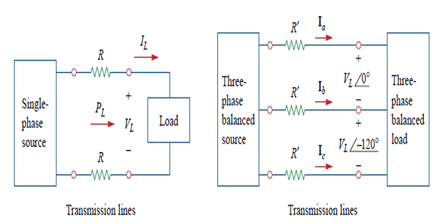
The economic case for three-phase transmission can be made precisely. Compare two systems delivering the same power \(P_{L}\) at the same line voltage \(V_{L}\) over the same distance, and require them to suffer the same losses.
Single-phase, two conductors:
Three-phase, three conductors: the line current is smaller by \(\sqrt{3}\) since \(P_{L} = \sqrt{3}V_{L}I'_{L}\), so
Requiring the losses to be equal gives
Since \(R = \rho\ell/A\), a resistance twice as large means a cross-section half as large: \(A' = A/2\). Now count the material, which is cross-section times length times number of conductors:
Single-phase transmission requires 33 % more conductor material than three-phase for the same power, voltage, distance and losses — equivalently, three-phase saves 25 % of the material. On a national transmission network that difference is measured in hundreds of thousands of tonnes of aluminium.
Two points about the derivation. It assumes the neutral can be dispensed with, which Section 12.4 established for balanced loads — a four-wire system would not show the same saving. And it holds the line voltage constant, which is the fair comparison because that is what insulation and clearances are designed for.
Unbalanced Three-Phase Systems
An unbalanced system is one in which the load impedances are not all equal. Real distribution systems are always somewhat unbalanced, because single-phase loads are connected between individual lines and neutral and never divide perfectly among the three.
Everything convenient about the balanced case now fails:
The three line currents differ in both magnitude and angle, so they no longer sum to zero.
The neutral carries current, and its value must be computed:
\[\mathbf{I}_{n} = -\left(\mathbf{I}_{a}+\mathbf{I}_{b}+\mathbf{I}_{c}\right)\]Per-phase analysis is invalid — there is no rotation that maps one phase onto another.
The formula \(P = \sqrt{3}V_{L}I_{L}\cos\theta\) does not apply. Each phase must be computed separately and the complex powers added.
The remedy is to fall back on the general methods of Chapter 10: mesh or nodal analysis on the complete three-phase circuit. There is nothing special about it — it is simply a larger AC circuit, and the phasor machinery handles it.


Why this matters in practice. The neutral conductor of a four-wire distribution system must be sized for the worst expected imbalance. Worse, a broken neutral on an unbalanced system allows the load's star point to shift away from earth potential, so that lightly loaded phases see voltages far above their rating — a well-known cause of appliance destruction across a whole building.
Problem. An unbalanced Δ-connected load has \(\mathbf{Z}_{A} = j5~\Omega\), \(\mathbf{Z}_{B} = 10~\Omega\) and \(\mathbf{Z}_{C} = -j10~\Omega\), supplied from a source whose line voltages give the mesh equations below. Find the line currents and the total complex power absorbed.
Solution. Mesh analysis on the two independent loops:
Solving gives
The line currents follow from the mesh currents:
Note that the three magnitudes are all different — 56.78, 25.46 and 42.76 A — which is the signature of an unbalanced system. No rotation relates them.
The complex powers must therefore be computed phase by phase:
All the real power comes from the single resistive phase, while the inductive and capacitive phases contribute only reactive power that partly cancels. Attempting \(P = \sqrt{3}V_{L}I_{L}\cos\theta\) here would be meaningless — there is no single \(I_{L}\) and no single \(\theta\).
The Two-Wattmeter Method
Measuring three-phase power might seem to need three wattmeters, one per phase. It does not. Two wattmeters suffice for any three-wire system, balanced or unbalanced, Y- or Δ-connected — and they yield the power factor as a bonus.
Connection. Each wattmeter's current coil carries one line current. Its voltage coil is connected between that line and the third line — the one carrying neither current coil. The \(\pm\) terminal of each voltage coil goes to the line whose current the corresponding current coil carries.
The word algebraic is important: one reading can be negative, and it must then be subtracted. Note also that the individual readings no longer correspond to the power in any particular phase — only their sum has meaning.
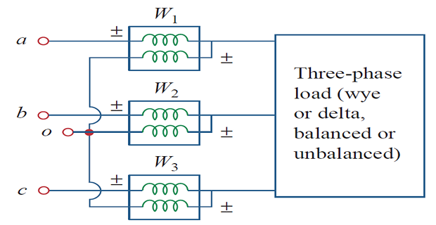
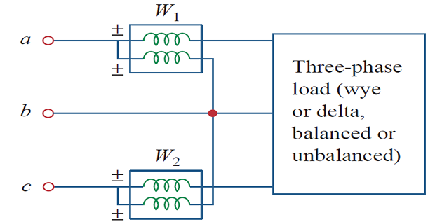
Take a balanced Y load of impedance \(\mathbf{Z}_{Y} = Z_{Y}\angle\theta\) in the abc sequence, so the phase voltage leads the phase current by \(\theta\). Recall that the line voltage leads its corresponding phase voltage by 30°. The total angle between \(\mathbf{V}_{ab}\) and \(\mathbf{I}_{a}\) is therefore \(\theta+30^{\circ}\), and by similar reasoning the angle between \(\mathbf{V}_{cb}\) and \(\mathbf{I}_{c}\) is \(\theta-30^{\circ}\). The two readings are
Adding them and expanding with \(\cos(A\pm B) = \cos A\cos B \mp \sin A\sin B\), the \(\sin\theta\sin30^{\circ}\) terms cancel:
which is exactly the total power of Section 12.7. Subtracting instead, the \(\cos\theta\cos30^{\circ}\) terms cancel and the \(\sin\) terms survive:
So the sum gives real power and the difference gives reactive power. Everything else follows:
From \(\tan\theta\) comes \(\theta\), and from \(\theta\) comes the power factor \(\cos\theta\). Two instruments therefore deliver \(P_{T}\), \(Q_{T}\), \(S_{T}\) and the power factor — a remarkable return for two readings.
| Relationship | Load | Power factor |
|---|---|---|
| \(P_{2} = P_{1}\) | resistive | unity |
| \(P_{2} > P_{1}\) | inductive | lagging |
| \(P_{2} < P_{1}\) | capacitive | leading |
| one reading zero | — | exactly 0.5 |
| one reading negative | — | below 0.5 |
The last two rows explain a common laboratory surprise. When \(\theta = 60^{\circ}\), the term \(\cos\left(\theta+30^{\circ}\right) = \cos 90^{\circ} = 0\) and \(P_{1}\) reads zero. Beyond 60° it goes negative, and the instrument's pointer tries to move backwards. The correct procedure is to reverse the connections of that wattmeter's current coil, take the reading as positive, and then subtract it. Recording it as positive without subtracting is the classic error in this experiment.
One limitation. The two-wattmeter method applies to three-wire systems only. In a four-wire system it fails unless the neutral current happens to be zero, because current can then return by a path that neither current coil monitors.
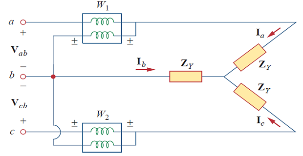
Problem. Two wattmeters are connected to measure the power of the system of Worked Example 12.4 (\(V_{L} = 207.8~\mathrm{V}\), \(I_{L} = 8~\mathrm{A}\), \(\theta = 36.87^{\circ}\)). Predict both readings, and verify that they reproduce the known \(P\), \(Q\) and power factor.
Solution. The two readings:
Total power:
exactly the value found in Example 12.4. Reactive power:
also exact. Power factor:
The method recovers the load angle exactly, and since \(P_{2} > P_{1}\) the table correctly identifies the load as inductive. Notice how unequal the two readings are — 653 W against 1651 W — even though the load is perfectly balanced. Neither reading corresponds to any phase's power, which is 768 W; only the sum is meaningful.
Practical Engineering Applications
The chain from generator to socket makes the theory concrete. A power station generates at perhaps 11 kV three-phase, which is transformed up to 220 kV or 400 kV for transmission — high voltage means low current for the same power, and hence low \(I^{2}R\) losses. It is stepped down in stages to a local distribution voltage, and finally to the four-wire system that reaches consumers.
In India that final system is 415 V between lines and 240 V between any line and neutral, the two figures related by \(\sqrt{3}\): \(415/\sqrt{3} = 239.6~\mathrm{V}\). In Europe the corresponding pair is 400 V and 230 V, and in North America 208 V and 120 V. Every one of these pairs is a \(\sqrt{3}\) ratio, and recognising it is a quick way to confirm that a system is three-phase four-wire.
A domestic consumer receives one phase and the neutral — hence "single-phase supply" — while an industrial consumer takes all three. Domestic loads are distributed among the three phases of the street feeder so that the system remains approximately balanced overall, which is why your neighbours may be on a different phase from you.
Loads that must be balanced. A three-phase motor is inherently balanced. Large single-phase loads — electric arc furnaces, railway traction, induction heaters — are not, and connecting one to a three-phase network causes voltage imbalance that other consumers experience as flicker. Utilities therefore impose limits on single-phase load size and require large ones to be connected through balancing arrangements.
The most important consumer of three-phase power is the induction motor, and the reason is worth stating. Three currents displaced by 120° in time, flowing in three windings displaced by 120° in space, produce a magnetic field of constant magnitude that rotates at the supply frequency. The rotor is dragged around by this field, and no starting arrangement is needed.
The field rotates at the synchronous speed
where \(p\) is the number of poles. At 50 Hz a four-pole machine runs at a synchronous speed of 1500 rev/min, which is why so many industrial machines are geared from that figure.
Reversing the motor requires only interchanging any two supply leads, which reverses the phase sequence and hence the direction of field rotation. That single fact — noted in Section 12.2 — is the practical reason phase sequence is worth checking before a machine is first energised.
Summary and Key Formulas
Three-phase systems deliver constant instantaneous power, save 25 % of conductor material, and permit self-starting motors.
Balanced voltages are equal in magnitude, 120° apart, and sum to zero. The sequence is abc (positive) or acb (negative).
For a Y connection: \(V_{L} = \sqrt{3}V_{p}\) with the line voltage leading by 30°, and \(I_{L} = I_{p}\).
For a Δ connection: \(V_{L} = V_{p}\), and \(I_{L} = \sqrt{3}I_{p}\) with the line current lagging by 30°.
For balanced loads \(\mathbf{Z}_{\Delta} = 3\mathbf{Z}_{Y}\). Convert everything to Y and analyse per-phase.
In a balanced Y–Y system the neutral current is zero and the neutral wire may be omitted.
Total power is \(P = \sqrt{3}V_{L}I_{L}\cos\theta\) for either connection, with \(\theta\) the load impedance angle.
The same impedances draw three times the power in Δ as in Y — the basis of the star–delta starter.
Unbalanced systems require mesh or nodal analysis; the neutral carries current and the \(\sqrt{3}\) power formula fails.
Two wattmeters measure any three-wire system, giving \(P_{T} = P_{1}+P_{2}\), \(Q_{T} = \sqrt{3}\left(P_{2}-P_{1}\right)\) and the power factor.
| Result | Formula | Notes |
|---|---|---|
| Balanced condition | \(\mathbf{V}_{an}+\mathbf{V}_{bn}+\mathbf{V}_{cn} = 0\) | equal magnitudes, 120° apart |
| abc sequence | \(V_p\angle0^{\circ},\ V_p\angle-120^{\circ},\ V_p\angle+120^{\circ}\) | positive sequence |
| Y: line voltage | \(V_{L} = \sqrt{3}V_{p}\) | leads phase voltage by 30° |
| Y: line current | \(I_{L} = I_{p}\) | same conductor |
| Δ: line voltage | \(V_{L} = V_{p}\) | same terminals |
| Δ: line current | \(I_{L} = \sqrt{3}I_{p}\) | lags phase current by 30° |
| Balanced load conversion | \(\mathbf{Z}_{\Delta} = 3\mathbf{Z}_{Y}\) | from wye–delta |
| Per-phase current | \(\mathbf{I}_{a} = \mathbf{V}_{an}/\mathbf{Z}_{Y}\) | then rotate \(\mp120^{\circ}\) |
| Balanced neutral current | \(\mathbf{I}_{n} = 0\) | neutral removable |
| Instantaneous power | \(p(t) = 3V_{p}I_{p}\cos\theta\) | constant |
| Total real power | \(P = 3V_{p}I_{p}\cos\theta = \sqrt{3}V_{L}I_{L}\cos\theta\) | either connection |
| Total reactive power | \(Q = \sqrt{3}V_{L}I_{L}\sin\theta\) | |
| Total apparent power | \(S = \sqrt{3}V_{L}I_{L}\) | |
| Y to Δ power ratio | \(P_{\Delta} = 3P_{Y}\) | same impedances |
| Material saving | \(2/1.5 = 1.333\) | 1φ needs 33 % more |
| Unbalanced neutral | \(\mathbf{I}_{n} = -\left(\mathbf{I}_{a}+\mathbf{I}_{b}+\mathbf{I}_{c}\right)\) | non-zero |
| Two wattmeters, \(P\) | \(P_{T} = P_{1}+P_{2}\) | algebraic sum |
| Two wattmeters, \(Q\) | \(Q_{T} = \sqrt{3}\left(P_{2}-P_{1}\right)\) | |
| Two wattmeters, pf | \(\tan\theta = \sqrt{3}\dfrac{P_{2}-P_{1}}{P_{2}+P_{1}}\) | then \(\mathrm{pf}=\cos\theta\) |
| Individual readings | \(P_{1,2} = V_{L}I_{L}\cos\left(\theta\pm30^{\circ}\right)\) | balanced load |
| Synchronous speed | \(N_{s} = 120f/p\) | rev/min |
Common Mistakes
Putting the \(\sqrt{3}\) in the wrong place. In Y it belongs to the voltage; in Δ to the current. Getting this backwards is the commonest error in the chapter.
Forgetting the 30° angle. Line and phase quantities differ in angle as well as magnitude. A magnitude-only answer is incomplete.
Using the line-to-line angle as \(\theta\) in the power formula. The \(\theta\) in \(P = \sqrt{3}V_{L}I_{L}\cos\theta\) is the load impedance angle, not the angle between \(\mathbf{V}_{L}\) and \(\mathbf{I}_{L}\).
Writing \(\mathbf{Z}_{Y} = 3\mathbf{Z}_{\Delta}\). It is the other way round: the delta impedance is the larger, \(\mathbf{Z}_{\Delta} = 3\mathbf{Z}_{Y}\).
Assuming the neutral current is zero in an unbalanced system. That result holds only for balanced loads, and the neutral conductor must be sized for the imbalance.
Applying \(P = \sqrt{3}V_{L}I_{L}\cos\theta\) to an unbalanced load. There is no single \(I_{L}\) or \(\theta\). Compute each phase separately and add the complex powers.
Adding two wattmeter readings when one is negative. The sum is algebraic; a negative reading must be subtracted.
Believing each wattmeter reads one phase's power. Neither does. Example 12.7 shows readings of 653 W and 1651 W where every phase carries 768 W.
Using the two-wattmeter method on a four-wire system with a non-zero neutral current. It is valid for three-wire systems only.
Confusing 240 V with 415 V. One is line-to-neutral, the other line-to-line, and they differ by \(\sqrt{3}\). Check which the problem means before computing anything.
Chapter Review
Work these before opening the answers. Assume the abc sequence throughout and state whether each power factor is leading or lagging.
P12.1 A balanced Y-connected source has \(V_{L} = 415~\mathrm{V}\). Find the phase voltage, and write all three phase voltages taking \(\mathbf{V}_{an}\) as reference.
Show answer
\[V_{p} = \frac{415}{\sqrt{3}} = 239.6~\mathrm{V}\]This is the standard Indian domestic and industrial supply.\[\mathbf{V}_{an} = 239.6\angle 0^{\circ}, \quad \mathbf{V}_{bn} = 239.6\angle-120^{\circ}, \quad \mathbf{V}_{cn} = 239.6\angle 120^{\circ}~\mathrm{V}\]P12.2 A balanced Y load of \(\left(9+j12\right)~\Omega\) per phase is fed from \(\mathbf{V}_{an} = 220\angle 0^{\circ}~\mathrm{V}\). Find the three line currents.
Show answer
\[\mathbf{Z}_{Y} = 9+j12 = 15\angle 53.13^{\circ}~\Omega\]\[\mathbf{I}_{a} = \frac{220\angle 0^{\circ}}{15\angle 53.13^{\circ}} = 14.67\angle-53.13^{\circ}~\mathrm{A}\]\[\mathbf{I}_{b} = 14.67\angle-173.1^{\circ}~\mathrm{A}, \qquad \mathbf{I}_{c} = 14.67\angle 66.87^{\circ}~\mathrm{A}\]P12.3 Find the total \(P\), \(Q\) and \(S\) for the load of P12.2.
Show answer
\[P = 3\left(220\right)\left(14.67\right)\left(0.6\right) = 5808~\mathrm{W}\]Check: \(\sqrt{5808^{2}+7744^{2}} = 9680\) VA \(\checkmark\), and the pf is 0.6 lagging.\[Q = 3\left(220\right)\left(14.67\right)\left(0.8\right) = 7744~\mathrm{VAR}, \qquad S = 3\left(220\right)\left(14.67\right) = 9680~\mathrm{VA}\]P12.4 A Δ load of \(\left(30+j40\right)~\Omega\) per phase is connected to a 400 V three-phase supply. Find the phase current, the line current, and the total power.
Show answer
\[\left|\mathbf{Z}_{\Delta}\right| = 50~\Omega, \qquad \theta = 53.13^{\circ}, \qquad I_{p} = \frac{400}{50} = 8~\mathrm{A}\]\[I_{L} = \sqrt{3}\left(8\right) = 13.86~\mathrm{A}\]\[P = \sqrt{3}\left(400\right)\left(13.86\right)\left(0.6\right) = 5760~\mathrm{W}\]P12.5 The same impedances of P12.4 are reconnected in star across the same supply. Find the new total power.
Show answer
Confirming directly: \(V_{p} = 400/\sqrt{3} = 230.9~\mathrm{V}\), \(I_{p} = 230.9/50 = 4.619~\mathrm{A}\), so \(P = 3(230.9)(4.619)(0.6) = 1920~\mathrm{W}\) \(\checkmark\)\[P_{Y} = \frac{P_{\Delta}}{3} = \frac{5760}{3} = 1920~\mathrm{W}\]P12.6 Convert a balanced Δ load of \(\left(36+j45\right)~\Omega\) per phase to its Y equivalent, and state the line current if \(V_{p} = 240~\mathrm{V}\).
Show answer
\[\mathbf{Z}_{Y} = \frac{36+j45}{3} = \left(12+j15\right)~\Omega = 19.21\angle 51.34^{\circ}~\Omega\]\[I_{L} = \frac{240}{19.21} = 12.49~\mathrm{A}\]P12.7 Two wattmeters read \(P_{1} = 1200~\mathrm{W}\) and \(P_{2} = 2400~\mathrm{W}\). Find the total power, the reactive power, and the power factor.
Show answer
\[P_{T} = 1200+2400 = 3600~\mathrm{W}, \qquad Q_{T} = \sqrt{3}\left(1200\right) = 2078~\mathrm{VAR}\]Lagging because \(P_{2} > P_{1}\).\[\tan\theta = \sqrt{3}\frac{1200}{3600} = 0.5774 \;\Longrightarrow\; \theta = 30.00^{\circ}, \qquad \mathrm{pf} = 0.8660\ \text{lagging}\]P12.8 Two wattmeters read \(P_{1} = -500~\mathrm{W}\) and \(P_{2} = 2500~\mathrm{W}\). Find the total power and power factor, and comment.
Show answer
\[P_{T} = -500+2500 = 2000~\mathrm{W}, \qquad Q_{T} = \sqrt{3}\left(3000\right) = 5196~\mathrm{VAR}\]The negative reading signals a power factor below 0.5. In the laboratory the meter would try to deflect backwards; reverse its current-coil connections, read it as positive, and subtract.\[\tan\theta = \sqrt{3}\frac{3000}{2000} = 2.598 \;\Longrightarrow\; \theta = 68.95^{\circ}, \qquad \mathrm{pf} = 0.3592\ \text{lagging}\]P12.9 An unbalanced Y load with a neutral has line currents \(\mathbf{I}_{a} = 10\angle 0^{\circ}\), \(\mathbf{I}_{b} = 12\angle-120^{\circ}\) and \(\mathbf{I}_{c} = 8\angle 120^{\circ}~\mathrm{A}\). Find the neutral current.
Show answer
Converting to rectangular: \(10\), \(-6-j10.39\), \(-4+j6.928\). Summing:\[\mathbf{I}_{a}+\mathbf{I}_{b}+\mathbf{I}_{c} = 0 - j3.464~\mathrm{A}\]Non-zero, as expected for an unbalanced load.\[\mathbf{I}_{n} = -\left(0-j3.464\right) = 3.464\angle 90^{\circ}~\mathrm{A}\]P12.10 A 415 V three-phase supply feeds a balanced load drawing 15 kW at 0.85 pf lagging. Find the line current and the reactive power.
Show answer
\[I_{L} = \frac{P}{\sqrt{3}V_{L}\cos\theta} = \frac{15\,000}{\sqrt{3}\left(415\right)\left(0.85\right)} = 24.55~\mathrm{A}\]\[\theta = \cos^{-1}0.85 = 31.79^{\circ}, \qquad Q = P\tan\theta = 15\,000\left(0.6197\right) = 9296~\mathrm{VAR}\]
MCQ 1. In a balanced Y connection, the line voltage:
(a) equals the phase voltage (b) is \(\sqrt{3}\) times the phase voltage (c) is three times the phase voltage (d) is \(1/\sqrt{3}\) of the phase voltageShow answer
(b), and it also leads the phase voltage by 30°.MCQ 2. In a balanced Δ connection, the line current:
(a) equals the phase current (b) is \(\sqrt{3}\) times the phase current (c) is three times the phase current (d) is zeroShow answer
(b), lagging the phase current by 30°. The \(\sqrt{3}\) attaches to the current in Δ and to the voltage in Y.MCQ 3. The neutral current in a balanced four-wire Y system is:
(a) \(\sqrt{3}I_{L}\) (b) \(3I_{L}\) (c) zero (d) equal to \(I_{L}\)Show answer
(c) zero, which is why the neutral can be omitted from a balanced system.MCQ 4. For a balanced load, \(\mathbf{Z}_{\Delta}\) equals:
(a) \(\mathbf{Z}_{Y}/3\) (b) \(3\mathbf{Z}_{Y}\) (c) \(\sqrt{3}\mathbf{Z}_{Y}\) (d) \(\mathbf{Z}_{Y}\)Show answer
(b) \(3\mathbf{Z}_{Y}\). The delta impedance is the larger of the two.MCQ 5. The total instantaneous power in a balanced three-phase system:
(a) pulsates at \(\omega\) (b) pulsates at \(2\omega\) (c) is constant (d) is zeroShow answer
(c) constant. The three \(2\omega\) components are 240° apart and cancel exactly — the chief reason for using three phases.MCQ 6. Three impedances draw 3 kW when connected in star. In delta across the same supply they draw:
(a) 1 kW (b) 3 kW (c) 5.196 kW (d) 9 kWShow answer
(d) 9 kW — three times. This is why a star–delta starter reduces the starting current to one third.MCQ 7. In \(P = \sqrt{3}V_{L}I_{L}\cos\theta\), the angle \(\theta\) is:
(a) between line voltage and line current (b) the load impedance angle (c) 30° (d) 120°Show answer
(b) the load impedance angle, equal to the angle between phase voltage and phase current. Option (a) differs from it by 30°.MCQ 8. If the two wattmeter readings are equal, the load is:
(a) purely resistive (b) purely inductive (c) purely capacitive (d) unbalancedShow answer
(a) purely resistive, unity power factor. Then \(Q_{T} = \sqrt{3}(P_{2}-P_{1}) = 0\).MCQ 9. One wattmeter reads zero. The power factor is:
(a) unity (b) 0.866 (c) 0.5 (d) zeroShow answer
(c) 0.5. A zero reading means \(\cos(\theta+30^{\circ}) = 0\), so \(\theta = 60^{\circ}\) and \(\cos 60^{\circ} = 0.5\).MCQ 10. Reversing the direction of a three-phase motor requires:
(a) reversing all three leads (b) interchanging any two leads (c) changing the frequency (d) adding a capacitorShow answer
(b) interchanging any two leads, which reverses the phase sequence and hence the rotating field.
The three \(2\omega\) power components cancel exactly in a three-phase system. Would the same happen in a two-phase or a four-phase system? What is special about three?
Explain, without algebra, why the \(\sqrt{3}\) attaches to voltage in a star connection but to current in a delta.
A balanced Y–Y system needs no neutral wire, yet domestic distribution is four-wire. Reconcile these two statements.
The same three impedances draw three times the power in delta as in star. Explain the factor of three in terms of the voltage each impedance sees, and say why the starting-current reduction in a star–delta starter is also a factor of three rather than \(\sqrt{3}\).
Two wattmeters measure three-phase power, and neither reading corresponds to any phase. Explain what each instrument is actually measuring, and why the sum is nonetheless correct even for an unbalanced load.
A broken neutral on an unbalanced four-wire system can destroy appliances. Explain the mechanism, and say which loads are most at risk — the heavily loaded phase or the lightly loaded one.
Every circuit so far has been connected by conductors: elements interact because current flows between them. Chapter 13 introduces a quite different mechanism, in which two circuits with no electrical connection at all influence one another through a shared magnetic field.
This is mutual inductance, and it makes the transformer possible — the device that has been assumed throughout this chapter whenever a voltage was "stepped up for transmission" or "stepped down for distribution". Chapter 13 explains how it works, introduces the dot convention for keeping track of winding polarities, and shows how a transformer's turns ratio can make a load impedance appear larger or smaller than it is.
That last property — impedance matching — connects directly back to Chapter 11. Maximum power transfer required a conjugate match, but a source and load rarely have conveniently matched impedances. A transformer can supply the missing ratio, and that is why the two topics belong together.