Set 27 — Power Flow and Efficiency
An induction motor is a chain of five conversions with a loss at every joint, and almost every question about its efficiency is answered by walking that chain in one direction or the other. This set drills the walk: stator input, stator copper loss, core loss, air-gap power, rotor copper loss, mechanical power developed, friction and windage, shaft output.
One relation carries the whole method. Because the rotor circuit contains \(R_2/s\) and dissipates \(3I_2^2R_2\), the air-gap power divides in the fixed ratio \(1 : s : (1-s)\) between what crosses the gap, what is lost as rotor heat and what emerges as mechanical power. Six problems use it forwards to find losses from a speed, backwards to find a speed from losses, and sideways to find the torque that the same air-gap power represents.
One chain, five subtractions. Power enters at the stator terminals and leaves at the shaft, losing something at every stage:
\[ P_1 \;\xrightarrow{\,-P_{cu1}\,}\; \;\xrightarrow{\,-P_i\,}\; P_g \;\xrightarrow{\,-P_{cu2}\,}\; P_m \;\xrightarrow{\,-P_{fw}\,}\; P_{out} \]Stator copper and core loss are taken at the stator; rotor copper loss inside the rotor; friction and windage at the shaft.
The slip splits the air-gap power in a fixed ratio, and this single line replaces most of the algebra in this set:
\[ P_g : P_{cu2} : P_m \;=\; 1 : s : (1-s) \]So \(P_{cu2} = sP_g\), \(P_m = (1-s)P_g\), and \(P_{cu2} = \dfrac{s}{1-s}P_m\) — whichever of the three is known gives the other two immediately.
Torque is air-gap power divided by synchronous speed, never by rotor speed:
\[ T = \frac{P_g}{\omega_s} = \frac{P_m}{\omega_m}, \qquad \omega_s = \frac{2\pi N_s}{60},\quad \omega_m = \frac{2\pi N}{60} \]The two forms agree because \(P_m = (1-s)P_g\) and \(\omega_m = (1-s)\omega_s\). The shaft torque is smaller: \(T_{sh} = P_{out}/\omega_m\).
The rotor's own efficiency is fixed by the slip alone. Whatever the machine, the rotor converts
\[ \eta_{rotor} = \frac{P_m}{P_g} = 1-s \]A motor running at 4% slip wastes 4% of everything crossing the air gap as rotor copper loss — which is why high-slip operation is thermally expensive.
Copper loss needs the phase current and the phase resistance. For a star stator the phase current is the line current; for a delta stator it is \(I_L/\sqrt3\). Read the connection before writing \(3I^2R\).
Overall efficiency and input power:
\[ P_1 = \sqrt3\,V_L I_L\cos\phi, \qquad \eta = \frac{P_{out}}{P_1} \]
A 100 kW, 3300 V, 50 Hz, 3-phase star-connected induction motor has a synchronous speed of 500 rpm. The full-load slip is 1.8% and the full-load power factor 0.85. The stator copper loss is 2440 W, the iron loss 3500 W and the rotational (friction and windage) losses 1200 W. Calculate
- the rotor copper loss
- the line current
- the full-load efficiency.
Fix the direction of travel first. The 100 kW is the shaft output, at the far end of the chain, and everything asked for lies upstream of it. So the whole solution runs backwards along the power flow:
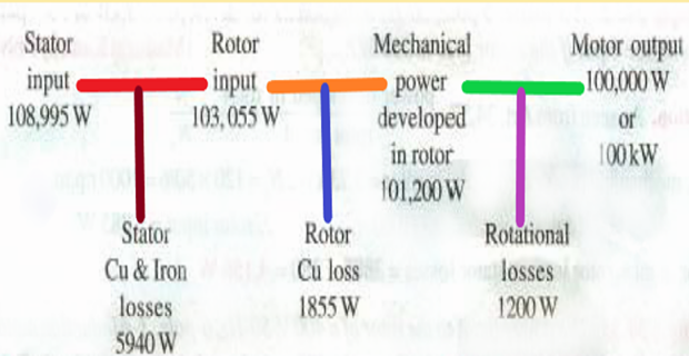
A 500 rpm synchronous speed at 50 Hz means \(P = 120f/N_s = 12\) poles, and the rotor runs at \(N = 500(1-0.018) = 491\) rpm.
Step back over the friction and windage to reach the mechanical power developed inside the machine:
This is the power the rotating field actually produces at the rotor; the bearings and the fan take 1.2 kW of it before anything reaches the coupling.
The rotor copper loss follows from the slip alone. Since \(P_{cu2} = sP_g\) and \(P_m = (1-s)P_g\), dividing one by the other removes \(P_g\):
No resistance, no current and no voltage were needed — the slip carries all the information.
Add it back to get the air-gap power (the rotor input):
Check: \(P_m/P_g = 101.2/103.055 = 0.982 = 1-s\), as it must be.
Cross the air gap backwards by restoring the two stator losses:
The line current now comes from the stator input, remembering the \(\sqrt3\) of a three-phase measurement:
The star connection does not enter here: \(\sqrt3 V_LI_L\cos\phi\) is the total three-phase power whatever the connection.
The efficiency is the ratio of the two ends of the chain:
The completed ledger, which is worth writing out because it is the shape of every problem in this set:
| Stage | Power | Loss removed |
|---|---|---|
| Stator input \(P_1\) | 108.995 kW | — |
| After stator copper | 106.555 kW | 2.440 kW |
| Air-gap power \(P_g\) | 103.055 kW | 3.500 kW iron |
| Mechanical developed \(P_m\) | 101.200 kW | 1.855 kW rotor copper |
| Shaft output \(P_{out}\) | 100.000 kW | 1.200 kW friction and windage |
Total loss 8.995 kW on 108.995 kW in — and the rotor copper loss, at 1.855 kW, is only the fourth largest of the five.
Two torques, one machine. The developed torque uses the air-gap power and synchronous speed; the shaft torque uses the output and the actual speed:
The 23 N·m difference is exactly the friction and windage torque, 1200 W at 491 rpm.
A 3-phase, 6-pole, 50 Hz induction motor draws 30 kW from the supply. The stator copper loss is 1.0 kW and the stator core loss 1.0 kW. A calorimetric measurement puts the rotor copper loss at 1.12 kW, and the friction and windage loss is 480 W. Determine
- the air-gap power
- the slip, the rotor speed and the rotor frequency
- the mechanical power developed and the shaft output
- the developed torque and the efficiency.
The air-gap power is what survives the stator. Both stator losses are taken before the gap:
Now read the slip straight off the loss ratio. Rotor copper loss is defined as the slip fraction of the air-gap power, so the slip is a measured quantity here rather than a speed measurement:
This is the practical value of the \(1 : s : (1-s)\) split: it turns a wattmeter reading into a speed without a tachometer.
The speed and rotor frequency follow at once:
The other two terms of the split:
Check the split adds up: \(1.12 + 26.88 = 28\ \text{kW} = P_g\).
Torque and efficiency. The developed torque uses synchronous speed:
Where the 3.6 kW of loss went, as a check that nothing has been counted twice:
| Loss | Value | Share of input |
|---|---|---|
| Stator copper | 1.00 kW | 3.3% |
| Stator core | 1.00 kW | 3.3% |
| Rotor copper | 1.12 kW | 3.7% |
| Friction and windage | 0.48 kW | 1.6% |
| Total | 3.60 kW | 12.0% |
And \(30 - 3.60 = 26.40\ \text{kW}\), the shaft output already found.
A 400 V, 50 Hz, 4-pole, 3-phase delta-connected induction motor draws a line current of 42 A at a power factor of 0.86 lagging and runs at 1440 rpm. The stator resistance is 0.4 Ω per phase, the iron loss 800 W and the friction and windage loss 350 W. Work the power flow through from the terminals to the shaft and find
- the stator input and the stator copper loss
- the air-gap power and the rotor copper loss
- the shaft output, the shaft torque and the efficiency.
Stator input from the line quantities:
The delta connection now matters. The 0.4 Ω is the resistance of one winding, and each winding carries only \(1/\sqrt3\) of the line current:
Using the line current instead would have given \(3\times42^2\times0.4 = 2117\ \text{W}\) — three times too much, and enough to wreck the efficiency figure at the end.
Cross the air gap by removing both stator losses:
The slip comes from the speed, and with it the rotor copper loss:
Mechanical power and shaft output:
Shaft torque and efficiency:
For comparison, the developed torque is \(P_g/\omega_s = 23\,519/157.08 = 149.7\ \text{N·m}\); the 2.3 N·m difference is the friction and windage.
A 3-phase, 8-pole, 50 Hz induction motor delivers 20 kW at the coupling while running at 720 rpm. The friction and windage loss is 600 W. Determine
- the slip and the rotor frequency
- the mechanical power developed
- the rotor copper loss and the rotor input (air-gap power)
- the developed and shaft torques
- the overall efficiency if the stator losses total 1.5 kW.
Slip from the two speeds:
Restore the friction and windage to reach the mechanical power the rotor actually develops:
This step must come first. The \(1:s:(1-s)\) split relates \(P_g\) to \(P_m\), not to \(P_{out}\) — the friction and windage sits outside the rotor circuit entirely.
The rotor copper loss from the ratio form of the split:
The rotor input is the sum, and can be checked two ways:
Equivalently the rotor is 96% efficient in itself: \(\eta_{rotor} = 1-s = 0.96\), independent of size, voltage or load.
The two torques:
Overall efficiency, once the stator losses are added at the front of the chain:
A 415 V, 50 Hz, 4-pole, 3-phase star-connected induction motor takes 28 A at a power factor of 0.88 lagging and runs at 1455 rpm. Its losses are: stator resistance 0.35 Ω per phase, core loss 700 W, friction and windage 400 W. Find the shaft torque and the efficiency, and state what fraction of the total loss each component represents.
Input power:
Stator copper loss. The stator is in star, so the phase current is the line current:
Air-gap power and slip:
The rotor split and the shaft output:
Shaft torque and efficiency:
The developed torque is \(16\,188/157.08 = 103.1\ \text{N·m}\), so 2.7 N·m of the torque produced is spent turning the machine itself.
Where the 2408 W of loss sits:
| Loss | Value | Share of total loss | Varies with |
|---|---|---|---|
| Stator copper | 823 W | 34.2% | Load current squared |
| Core loss | 700 W | 29.1% | Voltage and frequency — essentially fixed |
| Rotor copper | 486 W | 20.2% | Slip × air-gap power |
| Friction and windage | 400 W | 16.6% | Speed — essentially fixed |
| Total | 2408 W | 100% | — |
Fixed losses account for 1100 W and variable losses for 1309 W — close enough to equality that this machine is near its maximum-efficiency load, which is the maximum-efficiency condition of Set 20 for the transformer and holds here for the same reason.
A 440 V, 3-phase, 50 Hz, star-connected induction motor has a full-load speed of 1425 rpm. The rotor has an impedance of \((0.4+j4)\ \Omega\) per phase and a rotor/stator turns ratio of 0.8. Calculate
- the full-load torque
- the rotor current and the full-load rotor copper loss
- the power output if the windage and friction losses amount to 500 W
- the maximum torque and the speed at which it occurs
- the starting current
- the starting torque.
Synchronous speed and slip. A full-load speed of 1425 rpm at 50 Hz can only sit just below 1500 rpm, so the machine has four poles:
The standstill rotor e.m.f. The stator is in star, so each stator phase sees \(440/\sqrt3\), and the turns ratio scales that across to the rotor:
Full-load torque from the standard expression, with \(n_s = 25\) rev/s:
Rotor current, from the same impedance triangle:
Rotor copper loss, three phases of it:
Note the rotor actual resistance and the rotor actual current are used together — both are true rotor quantities, so no referral is needed.
Mechanical power and output. The cleanest route is through the air-gap power, since \(P_{cu2} = sP_g\):
Check against the torque: \(P_m = \omega_mT_{fl} = (2\pi\times1425/60)\times78.87 = 149.2\times78.87 = 11\,770\ \text{W}\) ✓ — the two routes agree exactly, as they must.
Maximum torque occurs where the rotor resistance equals the rotor reactance at that slip:
The slip speed at pull-out is \(s_bN_s = 150\) rpm, and the second form of \(T_{max}\) shows that its value does not contain \(R_2\) at all — only the slip at which it appears does.
Starting current and starting torque, both at \(s = 1\), where the full standstill e.m.f. drives the full standstill reactance:
The picture the six answers paint, which is the whole argument for a starting device:
| Condition | Slip | Rotor current | Torque |
|---|---|---|---|
| Starting | 1.00 | 50.6 A | 19.5 N·m |
| Pull-out | 0.10 | 35.9 A | 98.6 N·m |
| Full load | 0.05 | 22.7 A | 78.9 N·m |
At standstill the machine draws more than twice its full-load rotor current and produces a quarter of its full-load torque — because at \(s=1\) the rotor power factor is only \(0.4/4.02 = 0.10\), so almost none of that large current is doing useful work.
Key Formulas
| Quantity | Relation | Notes |
|---|---|---|
| Stator input | \(P_1 = \sqrt3\,V_LI_L\cos\phi\) | Line quantities, any connection — Problems 1, 3, 5 |
| Stator copper loss | \(P_{cu1} = 3I_{ph}^2R_1\) | Phase current: \(I_L\) in star, \(I_L/\sqrt3\) in delta — Problem 3 |
| Air-gap power | \(P_g = P_1 - P_{cu1} - P_i\) | Also called rotor input \(P_2\) — Problems 2, 3 |
| The power split | \(P_g : P_{cu2} : P_m = 1 : s : (1-s)\) | The governing relation of the set |
| Rotor copper loss | \(P_{cu2} = sP_g = \dfrac{s}{1-s}P_m\) | Also \(3I_2^2R_2\) — Problems 1, 4, 6 |
| Slip from losses | \(s = P_{cu2}/P_g\) | A wattmeter reading gives the speed — Problem 2 |
| Mechanical power | \(P_m = (1-s)P_g\) | Developed at the rotor, before windage |
| Shaft output | \(P_{out} = P_m - P_{fw}\) | Friction and windage leave at the shaft |
| Rotor efficiency | \(\eta_{rotor} = P_m/P_g = 1-s\) | Independent of everything but slip — Problem 4 |
| Developed torque | \(T = P_g/\omega_s = P_m/\omega_m\) | \(\omega_s = 2\pi N_s/60\) — Problems 2, 3, 4 |
| Shaft torque | \(T_{sh} = P_{out}/\omega_m\) | Always below \(T\) — Problems 3, 5 |
| Efficiency | \(\eta = P_{out}/P_1\) | Shaft output over terminal input |
| Rotor current | \(I_2 = sE_2/\sqrt{R_2^2+(sX_2)^2}\) | Actual rotor quantities — Problem 6 |
| Torque expression | \(T = \dfrac{3}{2\pi n_s}\dfrac{sE_2^2R_2}{R_2^2+(sX_2)^2}\) | \(n_s\) in rev/s — Problem 6 |
| Maximum torque | \(s_b = R_2/X_2,\quad T_{max} = \dfrac{3E_2^2}{2(2\pi n_s)X_2}\) | Value free of \(R_2\) — Problem 6 |
Common Mistakes
Applying the \(1:s:(1-s)\) split to the shaft output. The split relates \(P_g\) to \(P_m\), the mechanical power developed. Friction and windage must be added back first — Problems 1 and 4, where \(P_m\) exceeds \(P_{out}\) by 1.2 kW and 600 W respectively.
Dividing the air-gap power by the rotor speed to get torque. \(T = P_g/\omega_s\) uses synchronous speed; \(P_m/\omega_m\) is the same number written differently. Mixing them, as \(P_g/\omega_m\), inflates the torque by \(1/(1-s)\) — Problems 2 and 4.
Using the line current in \(3I^2R_1\) for a delta stator. Problem 3's 42 A line current is 24.25 A per winding; the wrong choice trebles the stator copper loss from 706 W to 2117 W.
Removing the iron loss from the rotor side. Core loss belongs to the stator, ahead of the air gap, because the rotor core sees only slip frequency — typically 2 Hz, where hysteresis and eddy-current loss are negligible. Problems 1, 3 and 5 all subtract it before \(P_g\).
Forgetting the factor of three. \(3I_2^2R_2 = 620\ \text{W}\) in Problem 6; using one phase gives 207 W and then a mechanical power a third of the correct value.
Quoting the shaft torque as the developed torque. They differ by the friction and windage torque — 2.3 N·m in Problem 3 and 2.7 N·m in Problem 5. Read which the question wants.
Treating efficiency as \(P_m/P_1\). That is the efficiency up to the rotor, not to the coupling. In Problem 5 it would give 88.7% instead of the correct 86.4%.
Assuming a low slip means low rotor loss in absolute terms. It means low loss as a fraction of the air-gap power. Problem 1's 1.8% slip still produces 1.855 kW of rotor heat, because \(P_g\) is 103 kW.
Using \(K\) on the line voltage. The turns ratio in Problem 6 multiplies the stator phase voltage, 254 V, not the 440 V line value — an error that raises every torque on the page by a factor of three.
The power flow has now been traced from terminals to coupling, and the single relation \(P_g:P_{cu2}:P_m = 1:s:(1-s)\) has done most of the work. It is worth noticing what was not needed: in Problems 1, 2 and 4 no resistance, reactance or turns ratio appeared at all. The slip alone divided the air-gap power, and the ledger did the rest.
That economy has a limit. Every problem here was handed either the input power or the output power as data. To predict them — to say what current a machine will draw and what torque it will produce at a given slip, from nothing but its winding data — the machine has to be represented as a circuit. The rotor resistance must be referred to the stator as \(R_2'\), the slip must appear inside it as \(R_2'/s\), and the magnetising branch must be put back.
Next: Set 28 — Equivalent Circuit Problems, where the per-phase circuit is solved for current, power factor and torque, the approximate form is compared with the exact one, and a Thevenin reduction locates the pull-out torque.