Set 28 — Equivalent Circuit Problems
Dividing the rotor equation by the slip replaces a rotating machine at slip frequency with a stationary circuit at supply frequency, and the whole of induction-motor performance becomes an exercise in solving that circuit. The slip survives in exactly one component, \(R_2'/s\), and every question about current, power factor, torque or efficiency is a question about how much power that one resistance receives.
These six problems work the circuit in both of its standard forms. Three use the approximate version, with the exciting branch moved to the terminals, because it reduces the machine to a single series impedance; two use the exact version and one compares them directly, so that the size and the direction of the approximation's error are known rather than assumed. The set closes with the Thevenin reduction that turns maximum torque into a maximum-power-transfer problem.
The rotor becomes a resistance that depends on speed. Referring the rotor to the stator and dividing through by the slip turns the whole machine into a static circuit:
\[ \frac{sE_2'}{R_2'+jsX_2'} \;\equiv\; \frac{E_2'}{(R_2'/s)+jX_2'} \]Nothing has been approximated: dividing numerator and denominator by \(s\) replaces a moving rotor at slip frequency by a stationary branch at supply frequency.
The slip-dependent resistance splits into two parts, and the split is the whole point of the circuit:
\[ \frac{R_2'}{s} = \underbrace{R_2'}_{\text{rotor heat}} + \underbrace{R_2'\!\left(\frac1s-1\right)}_{R_L' \;=\; \text{mechanical power}} \]So \(P_g = 3I_2'^2(R_2'/s)\), \(P_{cu2} = 3I_2'^2R_2' = sP_g\) and \(P_m = 3I_2'^2R_L' = (1-s)P_g\).
Exact circuit or approximate circuit. In the exact form the exciting branch hangs across the air-gap e.m.f., behind \(R_1+jX_1\); in the approximate form it is moved to the terminals, so the series branch carries \(I_2'\) alone:
\[ Z_{approx} = \left(R_1+\frac{R_2'}{s}\right)+j\left(X_1+X_2'\right), \qquad I_1 = I_0 + I_2' \]Torque from the air-gap power, always at synchronous speed:
\[ T = \frac{P_g}{\omega_s} = \frac{3I_2'^2 R_2'/s}{2\pi N_s/60} \]For maximum torque, reduce the stator side to a Thevenin source and apply maximum power transfer to \(R_2'/s\):
\[ \frac{R_2'}{s_{maxT}} = \sqrt{R_{Th}^2+(X_{Th}+X_2')^2}, \qquad T_{max} = \frac{3V_{Th}^2}{2\omega_s\!\left[R_{Th}+\sqrt{R_{Th}^2+(X_{Th}+X_2')^2}\right]} \]On the approximate circuit the same condition reads \(s_{maxT} = R_2'/\sqrt{R_1^2+(X_1+X_2')^2}\), with \(R_1\) and \(V_1\) in place of the Thevenin values.
The Thevenin quantities themselves:
\[ V_{Th} = V_1\frac{X_m}{\sqrt{R_1^2+(X_1+X_m)^2}}, \qquad Z_{Th} = \frac{jX_m(R_1+jX_1)}{R_1+j(X_1+X_m)} \]The magnetising branch is what the two circuits disagree about. Moving it forward makes \(I_2'\) too large, because it no longer sees the stator impedance drop — an error of a few per cent on a normal machine and much more on a small, high-leakage one.
A 440 V, 50 Hz, 6-pole, 3-phase star-connected induction motor has the following per-phase parameters referred to the stator: \(R_1 = 0.3\ \Omega\), \(X_1 = 0.6\ \Omega\), \(R_2' = 0.25\ \Omega\), \(X_2' = 0.6\ \Omega\). The exciting admittance measured at the terminals is \(Y_0 = (0.005 - j0.05)\) S per phase. Using the approximate equivalent circuit, determine at a slip of 3%
- the rotor current referred to the stator
- the no-load current and the stator current
- the supply power factor
- the air-gap power and the torque developed
- the mechanical power and the gross efficiency.
Set up the series branch. Take the phase voltage as reference and put the slip inside the rotor resistance:
In the approximate circuit this branch hangs directly across the supply, so it can be solved without knowing the air-gap e.m.f.
The referred rotor current:
Its power factor of \(\cos7.91^\circ = 0.990\) is excellent, because at 3% slip \(R_2'/s\) dominates the leakage reactance seven times over. This is why an induction motor's rotor behaves almost resistively at running speed.
The exciting current is now trivial, since the branch sits at the terminals:
Almost purely reactive, as an air-gapped magnetic circuit must be: the real part carries only the core loss.
Add the two currents to get the stator current:
Note how badly the magnetising current damages the power factor: the rotor draws its current at 0.99, and the machine as a whole manages only 0.875.
Air-gap power and torque. All the power entering \(R_2'/s\) crosses the gap:
Mechanical power and gross efficiency:
Confirm the input by adding the losses, which is the check that catches almost every slip in this kind of work:
| Term | Expression | Value |
|---|---|---|
| Stator copper loss | \(3I_2'^2R_1\) | 764 W |
| Core loss | \(3V_1^2G_0\) | 968 W |
| Air-gap power | \(3I_2'^2R_2'/s\) | 21 235 W |
| Total input | — | 22 967 W ✓ |
| of which rotor copper loss | \(sP_g\) | 637 W |
In the approximate circuit the stator copper loss uses \(I_2'\), not \(I_1\), because the exciting branch has been moved in front of the stator impedance. That is exactly the approximation being made.
A 115 V, 60 Hz, 3-phase, star-connected, 6-pole induction motor has an equivalent T-circuit consisting of a stator impedance of \((0.07+j0.3)\ \Omega\) and an equivalent rotor impedance at standstill of \((0.08+j0.3)\ \Omega\), both per phase. The magnetising branch has \(G_0 = 0.022\) S and \(B_0 = 0.158\) S. Using the approximate equivalent circuit at a slip of 2%, find
- the secondary (referred rotor) current
- the primary current
- the primary power factor
- the gross power output
- the gross torque
- the input power
- the gross efficiency.
Split the rotor resistance into its two parts. The mechanical-load resistance carries the gross output directly:
Equivalently \(R_2'/s = 4\ \Omega\), of which 0.08 Ω is rotor copper and 3.92 Ω is the mechanical load. At 2% slip 98% of the air-gap power is mechanical.
The impedance of the series branch, stator plus rotor plus load resistance:
The secondary current, with the phase voltage as reference:
The no-load current from the admittances:
10.6 A of exciting current against 16.1 A of load current — a very large ratio, typical of a small low-voltage machine, and the reason its power factor is poor.
The primary current and power factor:
The gross power output is the power dissipated in \(R_L'\) — that resistance is not a real resistance at all but the mechanical load:
The air-gap power is larger: \(P_g = 3I_2'^2(R_2'/s) = 3\times16.14^2\times4 = 3126\ \text{W}\), and the 63 W difference is the rotor copper loss, \(sP_g\).
Speeds and the gross torque:
The same number comes from \(P_g/\omega_s = 3126/125.66 = 24.87\ \text{N·m}\), as it must.
The input power, taken from the line quantities:
Equivalently \(3V_1\,\mathrm{Re}(I_1) = 3\times66.40\times17.43 = 3471\ \text{W}\) — the same calculation with the \(\sqrt3\) undone.
Check the input against the losses before dividing:
| Term | Expression | Value |
|---|---|---|
| Stator copper loss | \(3I_2'^2R_1\) | 54.7 W |
| Core loss | \(3V_1^2G_0\) | 291.0 W |
| Rotor copper loss | \(3I_2'^2R_2'\) | 62.5 W |
| Gross output | \(3I_2'^2R_L'\) | 3063 W |
| Total | — | 3471 W ✓ |
The gross efficiency:
It is called gross because friction and windage have not been deducted; the shaft efficiency would be a little lower.
A 220 V, 3-phase, 4-pole, 50 Hz, Y-connected induction motor is rated 3.73 kW. Its per-phase equivalent-circuit parameters are \(R_1 = 0.45\ \Omega\), \(X_1 = 0.8\ \Omega\), \(R_2' = 0.4\ \Omega\), \(X_2' = 0.8\ \Omega\), and the magnetising susceptance is \(B_0 = -1/30\) S, so that \(X_m = 30\ \Omega\). The stator core loss is 50 W and the rotational loss 150 W. For a slip of 0.04, determine
- the input current
- the power factor
- the air-gap power
- the mechanical power
- the electromagnetic torque
- the output power
- the efficiency.
Draw the exact circuit and identify the parallel section. Here the magnetising branch stays where it belongs, across the air-gap e.m.f., so the rotor branch and \(jX_m\) must be combined before anything else:
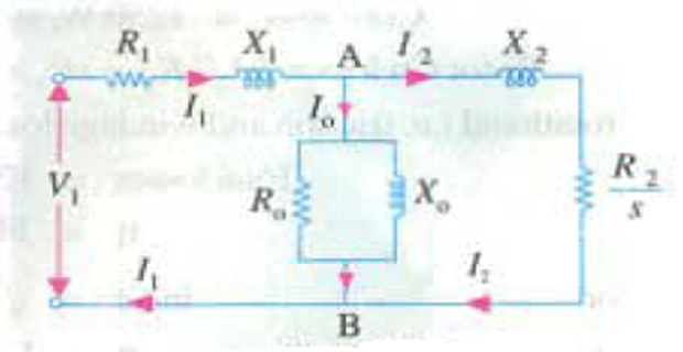
Combine the two branches at A–B:
Because \(jX_m\) is lossless, the real part 8.58 Ω represents only the power delivered to the rotor. That fact is used two steps below.
Add the stator impedance to get the whole circuit as seen by the supply:
The input current and power factor:
The air-gap power is the real power absorbed by \(Z_{AB}\):
Check it against the rotor current. Current division gives \(I_2' = I_1\dfrac{jX_m}{(R_2'/s)+j(X_2'+X_m)} = 11.73\ \text{A}\), and \(3\times11.73^2\times10 = 4127\ \text{W}\) ✓.
Mechanical power, speed and electromagnetic torque:
The output power, after the rotational loss:
Comfortably above the 3.73 kW rating, so 4% slip is a shade beyond full load for this machine.
The loss ledger and the efficiency. The core loss is not represented in this circuit — only \(B_0\) was given — so it must be added to the input by hand:
| Term | Expression | Value |
|---|---|---|
| Stator copper loss | \(3I_1^2R_1\) | 216 W |
| Rotor copper loss | \(sP_g\) | 165 W |
| Stator core loss | given | 50 W |
| Rotational loss | given | 150 W |
| Total loss | — | 581 W |
Repeat Problem 1 — the 440 V, 6-pole machine with \(R_1 = 0.3\ \Omega\), \(X_1 = 0.6\ \Omega\), \(R_2' = 0.25\ \Omega\), \(X_2' = 0.6\ \Omega\), \(Y_0 = (0.005-j0.05)\) S at 3% slip — using the exact equivalent circuit, in which the exciting branch is connected across the air-gap e.m.f. rather than across the terminals. Compare the stator current, power factor, air-gap power and torque with the approximate results, and say which way the approximation errs and why.
Convert the exciting admittance into a branch impedance, since the exact circuit needs it in series form:
So the magnetising reactance is 19.8 Ω against a stator leakage of 0.6 Ω — a ratio of 33, which is where the size of the eventual error comes from.
Combine the magnetising and rotor branches:
Add the stator impedance and solve:
Find the air-gap e.m.f. and the true rotor current:
Here is the whole difference in one line: the rotor sees 236.5 V, not the terminal 254 V, because the stator impedance drops 17.5 V on the way in. The approximate circuit hands the rotor the full terminal voltage.
Air-gap power, torque and efficiency on the exact circuit:
Ledger check: stator copper \(3I_1^2R_1 = 952\ \text{W}\), core loss \(3E_1^2G_m = 839\ \text{W}\), air-gap 20 037 W — total 21 828 W ✓.
The comparison:
| Quantity | Exact | Approximate | Error |
|---|---|---|---|
| Rotor current \(I_2'\) | 28.31 A | 29.14 A | +2.9% |
| Stator current \(I_1\) | 32.52 A | 34.46 A | +6.0% |
| Power factor | 0.881 | 0.875 | −0.7% |
| Air-gap power | 20 037 W | 21 235 W | +6.0% |
| Torque | 191.3 N·m | 202.8 N·m | +6.0% |
| Core loss | 839 W | 968 W | +15.4% |
| Gross efficiency | 89.0% | 89.7% | +0.7 pt |
Why the approximation always errs upwards. Moving the exciting branch to the terminals removes the stator impedance from in front of the magnetising branch and from in front of the rotor. Both currents are therefore driven by the full terminal voltage instead of by the smaller internal e.m.f.:
Torque goes as \(I_2'^2\), so a 2.9% current error becomes a 6.0% torque error. The approximation is optimistic about every performance figure except the power factor.
When the approximation is safe. The error scales with the ratio of the stator impedance to the magnetising impedance:
| Machine | \(X_m/X_1\) | Typical torque error |
|---|---|---|
| Large, high-voltage, low leakage | > 60 | < 2% — approximation fine |
| This machine | 33 | 6% — borderline |
| Small, low-voltage (Problem 2) | ≈ 21 | ≈ 10% — use the exact circuit |
The rule of thumb is that the approximate circuit is acceptable for machines above about 10 kW at normal supply voltages, and unreliable for fractional-kilowatt machines — which is precisely where the magnetising current is largest.
The per-phase equivalent circuit of a 400 V, 3-phase, star-connected induction motor, with all quantities referred to the stator at standstill, has a stator impedance of \((0.4+j1)\ \Omega\), a rotor impedance of \((0.6+j1)\ \Omega\) and a magnetising branch of \((10+j50)\ \Omega\). The synchronous speed is 1500 rpm. Using the approximate equivalent circuit, find
- the slip at which maximum torque occurs
- the maximum torque developed
- the supply power factor at a slip of 5%.
Recognise the condition for maximum torque as a maximum-power-transfer problem. The torque follows the air-gap power, which is the power delivered to the single resistance \(R_2'/s\). Since \(s\) is the only thing that varies, the torque peaks when that resistance matches the magnitude of the impedance looking back towards the source:
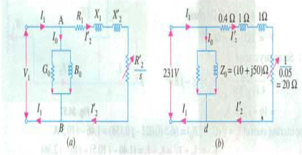
Substitute the data. The rotor impedance is \((0.6+j1)\ \Omega\), so \(R_2' = 0.6\ \Omega\) and \(X_2' = 1\ \Omega\):
A very high pull-out slip — this rotor has an unusually large resistance relative to its leakage reactance, which is what a high-starting-torque design looks like.
The referred rotor current at that slip, which is where the calculation is most often got wrong. The resistance in the loop is \(R_1+R_2'/s_{maxT}\), not \(R_1+R_2'\):
Using \(R_1+R_2' = 1\ \Omega\) instead would give 103 A — that is the standstill current, and it belongs to \(s=1\), not to \(s = 0.294\).
The maximum torque:
The closed form contains no \(R_2'\) at all, which is the standard result: rotor resistance moves the peak along the slip axis but does not change its height.
The power factor at 5% slip. Now \(R_2'/s = 0.6/0.05 = 12\ \Omega\), and the two parallel branches must be added:
How far below pull-out this operating point is:
| Slip | \(R_2'/s\) | \(I_2'\) | Torque |
|---|---|---|---|
| 0.05 | 12.00 Ω | 18.4 A | 77.5 N·m |
| 0.294 | 2.04 Ω | 73.2 A | 209 N·m |
| 1.00 | 0.60 Ω | 103.3 A | 122 N·m |
The current at standstill is only 41% larger than at pull-out, but the torque is lower, because at \(s=1\) most of that current is reactive. Torque follows \(I_2'^2R_2'/s\), and the resistance term collapses as the slip rises.
A 400 V, 50 Hz, 4-pole, 3-phase star-connected induction motor has per-phase parameters referred to the stator of \(R_1 = 0.5\ \Omega\), \(X_1 = 1.2\ \Omega\), \(R_2' = 0.4\ \Omega\), \(X_2' = 1.2\ \Omega\) and a magnetising reactance \(X_m = 40\ \Omega\); the core loss may be neglected. Reduce everything to the left of the rotor branch to a Thevenin equivalent and hence find
- \(V_{Th}\), \(R_{Th}\) and \(X_{Th}\)
- the slip at maximum torque and the speed at which it occurs
- the maximum torque
- the starting torque, and the ratio \(T_{st}/T_{max}\)
- how much the approximate circuit of Problem 5 would have got these wrong by.
Why a Thevenin reduction is needed at all. The maximum-power-transfer argument of Problem 5 requires a single source in series with a single impedance feeding \(R_2'/s\). The exact circuit does not have that form — \(jX_m\) sits in parallel. Removing the rotor branch and looking back gives exactly the required form.
The Thevenin voltage is the open-circuit voltage at the rotor terminals, a simple divider between \(jX_m\) and the stator impedance:
A 3% reduction on the terminal voltage — small, but it enters the torque squared.
The Thevenin impedance, with the source shorted:
The familiar shortcuts \(R_{Th}\approx R_1\left(\dfrac{X_m}{X_1+X_m}\right)^2 = 0.471\ \Omega\) and \(X_{Th}\approx X_1 = 1.2\ \Omega\) reproduce these to within 2.5%: \(R_{Th}\) is right to three figures and \(X_{Th}\) a shade high.
The slip at maximum torque is now the matching condition applied to the reduced circuit:
The maximum torque from the closed form:
Check from the current: at \(s_{maxT}\), \(R_2'/s = 2.417\ \Omega\) and \(I_2' = 224.2/\sqrt{(0.471+2.417)^2+2.371^2} = 60.0\ \text{A}\), giving \(3\times60.0^2\times2.417/157.08 = 166.2\ \text{N·m}\) ✓.
The starting torque, the same expression at \(s = 1\):
A cage machine of this design starts at just over a third of its pull-out torque while drawing 88.8 A against the 60.0 A at pull-out — the classic argument for a starter.
What the approximate circuit would have said. Replacing \(V_{Th}, R_{Th}, X_{Th}\) by \(V_1, R_1, X_1\):
| Quantity | Thevenin (exact) | Approximate | Error |
|---|---|---|---|
| Driving voltage | 224.2 V | 230.9 V | +3.0% |
| Series resistance | 0.471 Ω | 0.500 Ω | +6.2% |
| Series reactance | 1.171 Ω | 1.200 Ω | +2.5% |
| \(s_{maxT}\) | 0.165 | 0.163 | −1.4% |
| \(T_{max}\) | 166.2 N·m | 172.6 N·m | +3.8% |
The pull-out slip barely moves, because it depends on a ratio in which the two errors partly cancel; the pull-out torque moves by 3.8%, because \(V^2\) is not forgiving. As always the approximation is optimistic.
Key Formulas
| Quantity | Relation | Notes |
|---|---|---|
| Slip-dependent resistance | \(R_2'/s\) | The only place \(s\) enters the circuit |
| Mechanical-load resistance | \(R_L' = R_2'\left(\dfrac1s-1\right)\) | Carries \(P_m\) — Problem 2 |
| Approximate circuit | \(Z = (R_1+R_2'/s)+j(X_1+X_2')\) | Exciting branch at the terminals — Problems 1, 2, 5 |
| Exact circuit | \(Z_{01} = Z_1 + \dfrac{Z_m Z_2'}{Z_m+Z_2'}\) | Exciting branch behind \(Z_1\) — Problems 3, 4 |
| Stator current | \(I_1 = I_0+I_2'\) | Phasor sum — Problems 1, 2, 5 |
| Exciting current | \(I_0 = V_1Y_0 = V_1(G_0-jB_0)\) | Nearly all reactive |
| Air-gap power | \(P_g = 3I_2'^2(R_2'/s) = 3I_1^2R_{AB}\) | Second form only on the exact circuit — Problem 3 |
| Rotor copper loss | \(P_{cu2} = 3I_2'^2R_2' = sP_g\) | Set 27's split, in circuit form |
| Mechanical power | \(P_m = 3I_2'^2R_L' = (1-s)P_g\) | Gross, before windage |
| Torque | \(T = P_g/\omega_s = 9.55P_m/N\) | \(N\) in rpm in the second form |
| Thevenin voltage | \(V_{Th} = V_1\dfrac{X_m}{\sqrt{R_1^2+(X_1+X_m)^2}}\) | Problem 6 |
| Thevenin impedance | \(Z_{Th} = \dfrac{jX_m(R_1+jX_1)}{R_1+j(X_1+X_m)}\) | \(R_{Th}\approx R_1\left(\frac{X_m}{X_1+X_m}\right)^2,\ X_{Th}\approx X_1\) |
| Slip at maximum torque | \(s_{maxT} = \dfrac{R_2'}{\sqrt{R_{Th}^2+(X_{Th}+X_2')^2}}\) | Problems 5, 6 |
| Maximum torque | \(T_{max} = \dfrac{3V_{Th}^2}{2\omega_s\left[R_{Th}+\sqrt{R_{Th}^2+(X_{Th}+X_2')^2}\right]}\) | Independent of \(R_2'\) — Problems 5, 6 |
| Starting torque | \(T_{st} = \dfrac{3V_{Th}^2R_2'}{\omega_s\left[(R_{Th}+R_2')^2+(X_{Th}+X_2')^2\right]}\) | Same expression at \(s=1\) — Problem 6 |
Common Mistakes
Using the standstill resistance when the slip is not unity. At the pull-out slip of Problem 5 the loop resistance is \(R_1+R_2'/s_{maxT} = 2.44\ \Omega\), not \(R_1+R_2' = 1\ \Omega\). The wrong choice gives 103 A instead of 73.2 A and a torque wrong by a factor of well over two.
Calling \(3I_2'^2R_L'\) the air-gap power. It is the mechanical power. The air-gap power uses the full \(R_2'/s\); in Problem 2 the two differ by 63 W, which is precisely the rotor copper loss.
Reading \(R_2'\) off the wrong part of the rotor impedance. In Problem 5 the rotor is \((0.6+j1)\ \Omega\), so \(R_2' = 0.6\ \Omega\) and \(X_2' = 1\ \Omega\). Using 1 Ω as the resistance changes \(s_{maxT}\), \(T_{max}\) and the power factor together.
Applying the approximate-circuit stator copper loss to \(I_1\). When the exciting branch has been moved to the terminals, only \(I_2'\) flows in \(R_1\) — Problems 1 and 2. On the exact circuit, by contrast, \(I_1\) is correct, as in Problem 3.
Forgetting that the rotor never sees the terminal voltage. In Problem 4 the air-gap e.m.f. is 236.5 V against 254 V at the terminals, and that 7% shortfall becomes a 6% overestimate of torque when it is ignored.
Dividing the mechanical power by synchronous speed. \(T = P_g/\omega_s = P_m/\omega_m\); the cross combinations are both wrong by \(1/(1-s)\) — Problems 1 and 3.
Leaving the core loss out of the input when the circuit has no \(G_0\). Problem 3 gives only \(B_0\), so the 50 W of core loss is invisible to the circuit and must be added to \(3V_1I_1\cos\phi_1\) by hand.
Adding \(I_0\) and \(I_2'\) arithmetically. They are nearly in quadrature — in Problem 2, 10.6 A and 16.1 A give 21.6 A, not 26.7 A.
Expecting rotor resistance to change the peak torque. \(T_{max}\) contains no \(R_2'\); only \(s_{maxT}\) does. Problems 5 and 6 both show the peak moving along the slip axis at constant height.
Using \(V_1\) in the Thevenin torque formulae. Problem 6's driving voltage is 224.2 V, not 230.9 V; since torque goes as the square, the 3% error becomes nearly 4% in \(T_{max}\).
The machine is now a circuit. Six parameters — \(R_1\), \(X_1\), \(R_2'\), \(X_2'\) and the two components of the exciting branch — predict the current, the power factor, the torque and the efficiency at any slip, and a Thevenin reduction locates the pull-out point without further effort. Problem 4 also settled how much the convenient approximate form costs, and in which direction.
What has not been said is where those six numbers come from. They are not on the nameplate and cannot be calculated from the winding drawing with any accuracy. They are measured, by three tests that between them isolate the resistance of the stator, the shunt branch and the series branch: a DC measurement, a run at no load, and a run with the rotor held still.
Next: Set 29 — No-Load and Blocked-Rotor Testing, where each parameter of this set is extracted from wattmeter and ammeter readings, the blocked-rotor reactance is corrected for test frequency, and the leakage is divided between stator and rotor by design class.