Set 44 — Starting Methods and Capacitor Sizing
Set 41 proved that a single-phase motor develops no starting torque, because its forward and backward fields are exactly matched at standstill. Every starting method is a way of unmatching them: add a second winding 90 electrical degrees away in space, and force its current out of phase in time. The starting torque is then proportional to \(I_mI_a\sin\alpha\), and the design problem is to make \(\alpha\) as close to 90° as the economics allow.
The problems size starting and running capacitors, compute the phase split a resistive winding can achieve on its own, and distinguish two conditions that are often confused: a 90° current split, which merely maximises the torque, and the stronger requirement of equal mmfs, which removes the backward field altogether. The set closes by ranking the whole family of single-phase motors on starting torque per ampere of line current.
Two windings, displaced in space and in time. The auxiliary winding is wound 90 electrical degrees away from the main winding in space; the starting method's job is to make its current lead or lag the main current in time by an angle \(\alpha\). The starting torque follows the product
\[ T_{st} = K\,I_m I_a \sin\alpha \]Each winding angle comes from its own impedance, measured at standstill:
\[ \theta_m = \tan^{-1}\frac{X_m}{R_m}\ \text{(lag)}, \qquad \theta_a = \tan^{-1}\frac{X_a}{R_a}\ \text{(lag)}, \qquad \alpha = \theta_m - \theta_a \]A series capacitor turns the auxiliary lag into a lead. With \(X_C = 1/\omega C\) inserted:
\[ Z_{aw} = R_a + j\left(X_a - X_C\right), \qquad \theta_a = \tan^{-1}\frac{X_C-X_a}{R_a}\ \text{(lead)} \]For a 90° split the two tangents are reciprocals. Since \(\theta_a = 90^\circ-\theta_m\):
\[ \tan\theta_a = \cot\theta_m = \frac{R_m}{X_m} \;\Longrightarrow\; X_C = X_a + R_a\frac{R_m}{X_m}, \qquad C = \frac{1}{2\pi f X_C} \]For a genuinely single rotating field the backward mmf must vanish, which is a stronger condition than 90° alone — the two mmfs must also be equal:
\[ \mathcal{F}_b = \tfrac12\left(N_mI_m + jN_aI_a\right) = 0 \;\Longrightarrow\; Z_{aw} = -j\,\frac{N_a}{N_m}Z_m \]This fixes both the resistance and the reactance of the auxiliary branch, so it can be met exactly only at one speed. It is the design condition for a capacitor-run motor.
The forward and backward mmfs of a two-winding machine are the two-phase symmetrical components of the winding mmfs:
\[ \begin{bmatrix}\mathcal{F}_f\\\mathcal{F}_b\end{bmatrix} = \frac12\begin{bmatrix}1 & -j\\ 1 & j\end{bmatrix} \begin{bmatrix}N_mI_m\\N_aI_a\end{bmatrix} \]The line current is the phasor sum, not the arithmetic sum. \(I_L = I_m + I_a\) as phasors, and because the two are widely separated in angle the line current is always well below \(|I_m|+|I_a|\). Starting torque per ampere of line current is the figure of merit that separates the starting methods.
A single-phase, 230 V, 50 Hz, 4-pole capacitor-start induction motor has the following standstill impedances:
Determine the value of the starting capacitor required to produce a 90° phase difference between the currents in the main and auxiliary windings, and find the two winding currents and the total starting current.
Express both winding impedances in polar form, since the phase angles are what the problem is really about:
Without a capacitor the two currents are only 1.7° apart — effectively in phase — so the machine would have almost no starting torque at all. Both windings are inductive and very similar.
The main-winding current lags by \(\theta_m\). Nothing in the circuit can change this, because the capacitor goes in the auxiliary branch only:
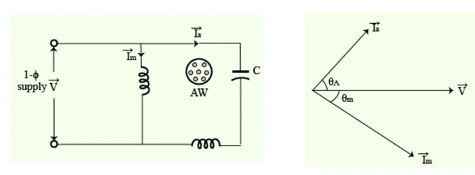
Add the capacitor in series with the auxiliary winding. Its reactance subtracts from the winding's own reactance and, if large enough, reverses the sign:
Impose the 90° condition. One current lags by \(\theta_m\), the other leads by \(\theta_a\), so the angle between them is the sum:
The reciprocal-tangent step is worth remembering: because \(\theta_a = 90^\circ-\theta_m\), the required tangent is \(R_m/X_m = 8/5\) exactly, with no rounding of the 32°.
Convert the reactance to a capacitance:
A capacitance of this size is an electrolytic unit, rated for intermittent duty only, which is exactly why a centrifugal switch must disconnect it once the motor is up to speed.
The two currents and the line current. With the capacitor fitted, \(Z_{aw} = 9 - j14.4 = 16.98\angle-58.0^\circ\ \Omega\):
Note the arithmetic sum of the magnitudes is 37.9 A but the line draws only 27.9 A, because the two currents are a right angle apart. The supply also sees a starting power factor of \(\cos2.95^\circ = 0.999\) — nearly unity, which is a second benefit of the capacitor entirely separate from the torque.
A 120 V, 60 Hz single-phase induction motor of the capacitor-start type has a main winding of 180 effective turns and an auxiliary starting winding of 250 effective turns. With the rotor stationary the input impedance of the main winding is \((5+j10)\ \Omega\) and that of the auxiliary winding is \((13.89+j15.50)\ \Omega\). Determine, at standstill,
- the magnitudes of the forward and backward rotating fields with no capacitor fitted
- the starting capacitor needed to yield a single rotating field.
The two winding currents at standstill. Both windings sit across the same 120 V:
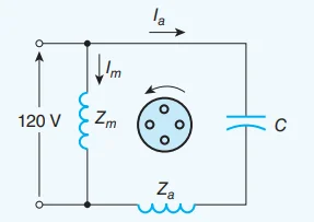
Only 15.3° separates them without a capacitor. The auxiliary winding's higher resistance does produce a split, but a feeble one.
(a) Resolve the two winding mmfs into rotating components. Because the windings are 90° apart in space, the forward and backward fields are the two-phase symmetrical components of \(N_mI_m\) and \(N_aI_a\):
The forward field exceeds the backward one by a factor of 1.29, so the machine does develop a net starting torque — but a poor one, and heavily contaminated by the backward field.
(b) A single rotating field means the backward mmf is zero. Set \(\mathcal{F}_b = 0\), with \(Z_a\) now standing for the auxiliary branch including the capacitor:
Equivalently \(Z_a = -j\left(N_a/N_m\right)Z_m\). The condition fixes the auxiliary branch completely: both its resistance and its reactance are prescribed.
The required resistance is already present. Comparing with the actual auxiliary branch \(Z_a = 13.89 + j(15.50-X_C)\), the resistances match at 13.89 Ω, so only the reactance has to be adjusted:
This machine has been designed so that its auxiliary winding resistance is exactly right; in general it is not, and only the 90°-split condition of Problem 1 can then be met.
Verify, and see what the capacitor buys. With \(Z_a = 13.889-j6.944 = 15.53\angle-26.57^\circ\ \Omega\):
The forward field rises from 1349 to 1932 A-turns — a 43% increase — while the backward field disappears entirely. The machine at standstill is now a true two-phase motor.
A 230 V, 50 Hz capacitor-start motor has standstill impedances \(Z_m = (6+j8)\ \Omega\) for the main winding and \(Z_a = (12+j5)\ \Omega\) for the auxiliary winding. Determine
- the starting capacitor that makes the two winding currents 90° apart
- the two winding currents and the total starting current
- the improvement in starting torque compared with the same motor started without a capacitor.
The main-winding angle, which the capacitor cannot alter:
(a) The auxiliary branch must lead by the complement:
(b) The currents. With the capacitor the auxiliary branch is \(Z_{aw} = 12-j9 = 15\angle-36.87^\circ\ \Omega\):
The line current is 27.6 A, well below the 38.3 A that the magnitudes would suggest, and the starting power factor is \(\cos19.4^\circ = 0.943\).
(c) Compare with the uncapacitored machine. Without the capacitor the auxiliary winding lags:
Form the torque ratio. The constant \(K\) and the main current cancel:
A 71% increase in starting torque, achieved with an auxiliary current 13% smaller than before. The capacitor reduced the auxiliary current (by raising the branch impedance from 13 Ω to 15 Ω) and still nearly doubled the torque, because the phase angle went from 30.5° to 90°.
A 230 V, 50 Hz split-phase induction motor has a main winding of standstill impedance \((3+j4)\ \Omega\) and a high-resistance auxiliary winding of standstill impedance \((9+j3)\ \Omega\). Determine
- the two winding currents and the phase angle between them
- the starting torque, in terms of the torque constant \(K\), and the line current at starting
- the capacitor that would convert it into a capacitor-start motor, and the resulting gain in starting torque and in torque per ampere of line current.
(a) The two currents. The main winding is low-resistance and highly inductive; the auxiliary winding is the reverse, and that contrast is the entire split-phase principle:
Both currents still lag the voltage; the split-phase motor never produces a leading current. Thirty-five degrees is about as far apart as resistance alone can push them, which caps the starting torque of the type.
(b) Starting torque and line current:
Because both currents lag, they add up rather than cancelling: the line draws 67.4 A out of a possible 70.2 A. A split-phase motor is hard on the supply for the torque it delivers.
(c) Fit a capacitor to reach a 90° split. The auxiliary branch must lead by \(90^\circ-53.13^\circ = 36.87^\circ\):
The capacitor-start performance:
Compare the two arrangements:
| Quantity | Split-phase | Capacitor-start | Change |
|---|---|---|---|
| Auxiliary current | 24.24 A lagging | 20.44 A leading | −16% |
| Phase split \(\alpha\) | 34.70° | 90° | — |
| Starting torque | \(635K\) | \(940K\) | +48% |
| Line current | 67.4 A | 50.3 A | −25% |
| Torque per ampere | \(9.42K\) | \(18.68K\) | +98% |
| Starting power factor | 0.752 | 0.873 | — |
The capacitor delivers 48% more torque while drawing 25% less line current, so the torque per ampere very nearly doubles. That double benefit — and not the torque alone — is why the capacitor-start motor displaced the split-phase motor wherever the extra cost could be justified.
A 230 V, 50 Hz capacitor-run motor has, at its rated running condition, a main-winding impedance of \((40+j50)\ \Omega\). The auxiliary winding has a resistance of 75 Ω and a reactance of 30 Ω, and carries \(N_a/N_m = 1.5\) times the effective turns of the main winding. Determine
- the run capacitor required for balanced two-phase operation, i.e. for a zero backward field
- the two winding currents, and verify that the balance conditions are met
- the line current, the supply power factor and the input power.
(a) Write the zero-backward-field condition. With the two windings 90° apart in space, the backward mmf vanishes when \(N_mI_m + jN_aI_a = 0\); putting \(I_m = V/Z_m\) and \(I_a = V/Z_{aw}\) and cancelling \(V\):
The required resistance, 75 Ω, is exactly what the auxiliary winding already has — the machine was designed that way. Only the reactance has to be supplied.
Size the capacitor. The auxiliary branch reactance must go from \(+30\ \Omega\) to \(-60\ \Omega\):
Compare with the 227 µF starting capacitor of Problem 3. A run capacitor is an order of magnitude smaller because it is sized for the running impedance, which is far higher than the standstill impedance — and it must be an oil-filled unit rated for continuous duty, since it stays in circuit permanently.
(b) The two currents:
Check both balance conditions. Time displacement first:
Then equality of the two mmfs:
Both are satisfied, so \(\mathcal{F}_b = 0\): the machine runs as a balanced two-phase motor with a single forward field. No backward field means no backward rotor loss, no braking torque, and none of the double-frequency torque pulsation that makes a plain single-phase motor noisy.
(c) The line current and supply conditions:
Check against the two branches directly: \(I_m^2\times40 + I_a^2\times75 = 516+430 = 946\) W. Note also that the main winding alone would have run at \(\cos51.34^\circ = 0.625\); the leading auxiliary current has pulled the overall power factor up to 0.953. The run capacitor is simultaneously a field-balancing device and a power-factor correction capacitor.
The 230 V, 50 Hz machine of Problem 4, whose main winding has a standstill impedance of \((3+j4)\ \Omega\), is to be started three different ways:
- Split-phase — auxiliary winding \((9+j3)\ \Omega\), no capacitor
- Capacitor-start — the same auxiliary winding with the 326 µF capacitor of Problem 4
- Shaded-pole — no auxiliary winding across the line; the shading rings produce an equivalent auxiliary current of 6.0 A referred to the main winding, displaced 25° from the main current.
Compare the three on starting torque, line current at starting, and starting torque per ampere of line current.
The main winding is common to all three and is unaffected by whatever happens in the auxiliary circuit:
So any difference between the three methods lies entirely in \(I_a\) and \(\alpha\).
Split-phase — carried over from Problem 4:
Capacitor-start — also from Problem 4:
Shaded pole. The shading ring is a closed copper loop around part of the pole; it is not fed from the supply, so it adds nothing to the line current. Its induced current lags the main flux and produces a small mmf displaced from the main one:
The shading ring's current circulates entirely within the machine, which is why the line current equals the main-winding current alone — the one respect in which the shaded-pole motor looks good.
Collect the comparison:
| Method | \(I_a\) (A) | \(\alpha\) | \(T_{st}\) | \(I_L\) (A) | \(T_{st}/I_L\) | Relative |
|---|---|---|---|---|---|---|
| Capacitor-start | 20.44 | 90.0° | \(940K\) | 50.3 | \(18.68K\) | 1.00 |
| Split-phase | 24.24 | 34.7° | \(635K\) | 67.4 | \(9.42K\) | 0.50 |
| Shaded-pole | 6.0 (internal) | 25.0° | \(117K\) | 46.0 | \(2.54K\) | 0.14 |
Read the table the right way round. The shaded-pole motor draws the lowest line current of the three, yet has by far the worst torque per ampere, because its equivalent auxiliary current is small and badly displaced. The split-phase motor has the highest line current and only two-thirds of the capacitor-start torque. Ranking by torque per ampere:
Roughly 2:1 and then 3.7:1. That ordering, and not the absolute numbers, is what should be carried away: a shaded-pole motor is used because it costs almost nothing and needs no switch, never because it starts well.
Where each is used. The comparison explains the market: shaded-pole motors drive fans and pumps, which need almost no starting torque; split-phase motors handle light general-purpose loads; capacitor-start motors are specified where the load must be broken away from rest — compressors, conveyors, and anything with static friction.
Key Formulas
| Quantity | Relation | Notes |
|---|---|---|
| Starting torque | \(T_{st} = K I_m I_a \sin\alpha\) | Maximum at \(\alpha=90^\circ\) — Problems 3, 4, 6 |
| Winding phase angles | \(\theta = \tan^{-1}(X/R)\) | Both lag without a capacitor — Problem 4 |
| Split-phase angle | \(\alpha = \theta_m-\theta_a\) | 34.7° — Problem 4 |
| Auxiliary branch with capacitor | \(Z_{aw} = R_a + j(X_a-X_C)\) | Problems 1, 3, 4, 5 |
| Condition for a 90° split | \(\tan\theta_a = \cot\theta_m = R_m/X_m\) | Exact, no rounding of angles — Problems 1, 3 |
| Starting capacitor | \(X_C = X_a + R_a R_m/X_m,\quad C = 1/(2\pi f X_C)\) | 156 µF, 227 µF, 326 µF — Problems 1, 3, 4 |
| Two-phase symmetrical components | \(\mathcal{F}_{f,b} = \tfrac12\left(N_mI_m \mp jN_aI_a\right)\) | Problem 2 |
| Zero backward field | \(Z_{aw} = -j\left(N_a/N_m\right)Z_m\) | Fixes both R and X — Problems 2, 5 |
| Balance conditions | \(\alpha = 90^\circ\) and \(N_aI_a = N_mI_m\) | Both needed — Problems 2, 5 |
| Line current at starting | \(\vec{I}_L = \vec{I}_m+\vec{I}_a\) | Phasor sum — Problems 1, 3, 4 |
| Torque per ampere | \(T_{st}/\left|\vec{I}_L\right|\) | The figure of merit — Problems 4, 6 |
| Capacitive reactance | \(X_C = 1/(2\pi f C)\) | Larger \(C\) means smaller \(X_C\) |
| Run capacitor | \(X_C = X_a + \left(N_a/N_m\right)R_m\) with \(R_a = \left(N_a/N_m\right)X_m\) | 35.4 µF — Problem 5 |
| Starting power factor | \(\cos\phi_L\) from \(\vec{I}_L\) | 0.999, 0.943, 0.752 — Problems 1, 3, 4 |
Common Mistakes
Subtracting the two angles when one of them leads. With a capacitor the main current lags and the auxiliary current leads, so the split is \(\theta_m+\theta_a\). Setting \(\theta_m-\theta_a = 90^\circ\) in Problem 1 demands a negative auxiliary angle, which no positive capacitance can produce.
Adding the winding currents arithmetically to get the line current. Problem 1's line current is 27.9 A, not \(24.4+13.5 = 37.9\) A; the two currents are a right angle apart and must be added as phasors.
Confusing the main-winding current with the total. Problem 4's main winding takes 46 A while the line takes 67.4 A; using the wrong one halves the torque-per-ampere figure or doubles it, depending on the direction of the error.
Assuming a 90° split gives a single rotating field. It does not: Problem 1 achieves 90° but leaves the two mmfs unequal, so a backward field survives. Only the stronger condition \(Z_{aw} = -j(N_a/N_m)Z_m\) of Problems 2 and 5 removes it.
Sizing the capacitor from the total auxiliary reactance instead of the difference. In Problem 3, \(X_C\) must be 14 Ω, of which 5 Ω merely cancels the winding's own reactance; taking \(X_C = 9\) Ω gives \(Z_{aw} = 12-j4\), a lead of only 18.4° and a split of 71.5° rather than 90°.
Believing a bigger capacitor always helps. Overshooting 90° reduces \(\sin\alpha\) again while continuing to reduce \(I_a\), so the torque falls on both counts — Problem 3.
Assuming a larger auxiliary current means more torque. Problem 3's capacitor reduced \(I_a\) from 17.7 A to 15.3 A and still raised the torque by 71%, because the angle went from 30.5° to 90°.
Using the same capacitor for starting and running. Problem 3 needs 227 µF at standstill; Problem 5 needs 35.4 µF while running, because the running impedance is much higher. A start capacitor left in circuit will fail, being an electrolytic rated for a few seconds per hour.
Counting the shading-ring current in the line current. The ring is a shorted turn inside the machine and draws nothing from the supply, so a shaded-pole motor's line current is its main-winding current — Problem 6.
Judging a starting method by torque alone. The split-phase motor of Problem 6 produces 5.4 times the shaded-pole torque but draws 47% more line current; torque per ampere is the comparison that matters, and it ranks the three methods 18.68 : 9.42 : 2.54.
Part 6 has now dealt with the single-phase induction motor completely: why it cannot start itself, how its two revolving fields are represented in an equivalent circuit, how that circuit's parameters are measured, and how a second winding is used to break the symmetry at standstill. Every one of those problems came back to the same pair of numbers, \(s\) and \(2-s\).
The remaining single-phase machines take an entirely different route to the same end. A series-wound machine produces torque from the product of two quantities that reverse together, so it does not care about the sign of the supply at all and runs on a.c. or d.c. with equal willingness — and it starts without any auxiliary winding whatsoever.
Next: Set 45 — Universal and AC Series Motors, where the same machine is analysed on d.c. and on a.c., the reactance drop and the reduced power factor are accounted for, and the speed–torque behaviour that puts these motors in every hand tool is worked out.