By the end of this chapter you should be able to:
Describe the main and teaser transformers and how they are connected.
Show that the teaser tap of 0.866 is the altitude of the voltage triangle.
Explain why equal volts per turn makes both secondary voltages equal.
Prove that the two-phase output is exactly 90° apart.
Derive the current relations and show that the three-phase supply stays balanced.
Locate the neutral point on the teaser winding.
Compute the utilisation factor and relate it to the open-delta result.
State the applications of the connection.
The Problem It Solves
A large single-phase load — an electric furnace, or a traction substation feeding a railway — drawn directly from two lines of a three-phase system unbalances that system badly. The two supplying phases carry current and the third carries none.
The Scott connection takes a balanced three-phase supply and produces two separate single-phase outputs in quadrature. If those two outputs are equally loaded, the three-phase supply remains perfectly balanced.
The two outputs together form a two-phase system, which is what gives the connection its name.
The connection was proposed by Charles F. Scott. It converts three-phase to two-phase and, in principle, back again — though as Section 55-9 notes, only one direction is used in practice.
The Scott Connection

Two transformers are used, and their windings form the shape of a letter T — hence the alternative name T-T connection.
Has centre taps on both primary and secondary. Its primary forms the horizontal member of the T, connected across two of the three supply lines.
Tapped at 0.866 of its winding. One end of its primary and secondary is joined to the centre tap of the main primary and secondary respectively.
The other end \(A_1\) of the teaser primary, and the two ends \(B_1\) and \(C_1\) of the main transformer primary, are connected to the three-phase supply.

Why the Teaser Is Tapped at 0.866
The figure 0.866 is not chosen; it is forced by the geometry of a balanced three-phase voltage system.
Draw the three supply line voltages as the sides of an equilateral triangle \(ABC\). The main primary lies along \(BC\), and its centre tap \(D\) is the midpoint of that side. The teaser primary must reach from \(D\) to \(A\).
The teaser must therefore develop 86.6 % of the line voltage, so it is tapped at 0.866 of the main winding.
The same \(\sqrt3/2\) appeared in Chapter 53 as the open-delta utilisation factor. It will appear again in Section 55-8 as the utilisation factor of this connection — arriving there by a completely different argument, and giving the same number.
Problem. A three-phase supply has \(V_L = 100\) V and the transformation ratio is \(K = 1\). Find the voltages across the main primary, its two halves, and the teaser primary.
Main primary, connected across \(BC\):
Its two halves, since \(D\) is the centre tap:
These two differ by \(180^{\circ}\), because both coils are on the same magnetic circuit and are connected in opposition.
Teaser primary, the altitude of the triangle:
Comment. Each side of the equilateral triangle represents 100 V, and \(E_{DA}\) is 86.6 V lagging the voltage across the main by \(90^{\circ}\).
Note that the teaser is not tapped so as to receive a smaller voltage arbitrarily. It is tapped at exactly the point where the winding voltage matches what the supply geometry offers between \(D\) and \(A\) — anything else would leave a mismatch and force a circulating current.
Equal Volts per Turn
Here is the point that makes the connection work, and the one the geometry alone does not explain: why do the two secondaries deliver equal voltages when their primaries do not receive equal voltages?
Let the main primary have \(N_1\) turns. The teaser primary has \(0.866N_1\) turns and receives \(0.866V_L\).
The volts per turn are identical. Both secondaries therefore have \(N_2\) full turns and deliver the same voltage \(V_L/K\).
Why the Output Is Exactly 90°

The quadrature relation is a property of the triangle, not an approximation.
Therefore \(E_{DA}\) is at \(90^{\circ}\) to \(E_{BC}\), exactly.
Each secondary voltage is in phase with its own primary voltage. So the main secondary is along \(BC\) and the teaser secondary is along \(DA\) — two voltages, equal in magnitude and exactly 90° apart.
The same relation holds in the secondary winding, so that \(abc\) is a symmetrical three-phase system on that side too, should three-phase output be wanted instead.
Problem. Place the triangle on axes and confirm that the two output voltages differ by exactly \(90^{\circ}\).
Coordinates, with \(D\) at the origin and \(BC\) along the real axis:
The two voltages.
Phase difference.
Comment. On the primary side the magnitudes differ, 100 V against 86.60 V. On the secondary side they are equal, because of the volts-per-turn argument of Section 55-4 — and the 90° carries through unchanged, since each secondary is in phase with its own primary.
The output is therefore a genuine balanced two-phase system: two equal voltages in quadrature. This is what a two-phase induction motor or a two-phase distribution system requires.
Currents and the Balance of the Supply
The claim that the three-phase supply stays balanced needs proof, and it comes from ampere-turn balance on each transformer.
where \(K = N_1/N_2\). The teaser primary carries \(1/0.866 = 1.1547\) times the current an equivalent full winding would, because it has fewer turns to do the same ampere-turns.
That current \(I_T\) is drawn entirely from line \(A\). Meanwhile the total power balance fixes the line current of a balanced three-phase supply:
Example 55.3 shows that these two expressions give the same number — which is the proof that the connection balances the supply.
Problem. With \(V_L = 100\) V and \(K = 1\), each of the two secondary phases supplies 10 A at unity power factor. Find the teaser primary current and the three-phase line current, and compare.
Total power delivered.
Line current required of a balanced three-phase supply.
Teaser primary current, from ampere-turn balance.
Comparison.
Comment. The current drawn from line \(A\) by the teaser is exactly the line current a balanced three-phase load of the same power would draw. All three line currents are equal, so the supply sees a balanced load — which is the whole purpose of the connection.
Note that this holds only when the two secondary phases are equally loaded. If one two-phase output is loaded more heavily than the other, the three-phase side becomes unbalanced in proportion. The Scott connection converts a balanced two-phase load into a balanced three-phase one; it does not magically balance an unbalanced load.
The factor \(2/\sqrt3 = 1.1547\) is worth remembering. It is the ratio of three-phase line current to two-phase phase current at the same voltage and power — and its reciprocal, 0.866, is the same \(\sqrt3/2\) yet again.
Locating the Neutral
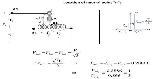
Where a three-phase four-wire supply is wanted, the neutral must be brought out. Its position follows from the same triangle.
The neutral of a balanced three-phase system is equidistant from all three line terminals — that is, the centroid of the triangle \(ABC\). In an equilateral triangle the centroid lies at one third of any median from the base:
So the neutral is tapped at one third of the teaser winding, measured from the end joined to the main's centre tap.
Expressed against the main winding instead, the tap is at \(0.2887\) of the full main winding — but it is more natural to state it as one third of the teaser, since that is the winding it is actually on.
Problem. For the 100 V system, find the distance from \(D\) to the neutral, and verify that the point is equidistant from \(A\), \(B\) and \(C\).
Position of the neutral.
Distance to \(A\), along the same line:
Distance to \(B\), by Pythagoras, since \(DB = 50\) and \(DN = 28.87\) are perpendicular:
By symmetry \(NC = 57.735\) V also.
Check against the expected phase voltage.
Comment. All three distances come to 57.735 V, which is exactly \(V_L/\sqrt3\). The point one third along the teaser is therefore the true neutral of the three-phase system, and a fourth wire taken from it gives a proper four-wire supply.
The check on \(NB\) is the convincing one, because it uses a quite different route — Pythagoras across two perpendicular segments rather than subtraction along a line — and still lands on the same number.
Power Factors and Utilisation

With reference to the secondary voltage triangle, for a unity-power-factor load, \(I_{db}\) lags \(E_{db}\) by \(30^{\circ}\) and \(I_{dc}\) leads \(E_{dc}\) by \(30^{\circ}\). In other words, the teaser and each half of the main transformer all operate at different power factors.
The teaser operates at only 0.866 of its rated voltage, so it uses 86.6 % of its kVA.
The main transformer coils operate at \(\cos30^{\circ} = 0.866\) power factor, which is equivalent to those coils working at 86.6 % of their kVA rating.
Hence the capacity-to-rating ratio in a T-T connection is 86.6 % — the same as in the V-V connection of Chapter 53, if two identical units are used.
Obviously, the full rating of the transformers is not being utilised. The shortfall is not a loss in the sense of heat; it is capacity that simply cannot be reached, exactly as in the open delta.
Problem. For the system of Example 55.3, compute the installed transformer VA and compare it with the power delivered.
Installed rating. Each transformer is wound for the full line voltage and must carry the line current:
Power delivered.
Utilisation factor.
Comment. The figure \(\sqrt3/2\) has now appeared three times in this chapter — as the teaser tap, as the main coils' power factor, and as the utilisation factor — and once in Chapter 53 as the open-delta utilisation factor.
It is the same geometrical fact each time: the altitude of an equilateral triangle is \(\sqrt3/2\) of its side. Every three-phase connection that works with two transformers rather than three ends up paying this factor somewhere.
The practical reading: to deliver 2000 W of two-phase load, 2309 VA of transformer must be installed — about 15.5 % more than the load, which is the same \(2/\sqrt3\) penalty computed for the open delta in Chapter 53.
Applications
Electric furnace installations, where it is desired to operate two single-phase furnaces together and draw a balanced load from the three-phase supply.
Single-phase loads such as electric traction, which are scheduled so as to keep the load on the three-phase system as nearly balanced as possible.
To link a three-phase system with a two-phase system, with power flowing in either direction.
The Scott-T connection permits conversion of a three-phase system to a two-phase system and vice versa. But since two-phase generators are not available, converters from two phases to three phases are not used in practice.
Two-phase systems were common in early power distribution — Nikola Tesla's original polyphase patents were two-phase — but three-phase won decisively on economics, needing three conductors rather than four for the same power. The Scott connection survives chiefly as a way of drawing balanced power for single-phase loads, not for feeding genuine two-phase networks.
The traction application is the most important survivor. A railway substation feeds a single-phase catenary, and taking that load from two lines of the grid would unbalance it severely. Two Scott-connected outputs feeding two adjacent track sections present a balanced load to the grid whenever both sections carry similar traffic.
Summary and Key Formulas
The Scott or T-T connection, proposed by Charles F. Scott, converts three-phase to two-phase using two transformers connected electrically but not magnetically.
The main transformer is centre-tapped on both windings and forms the horizontal member; the teaser is tapped at 0.866 and joins the main's centre tap.
The tap is \(\sqrt3/2\) because \(DA\) is the altitude of the equilateral voltage triangle: \(E_{DA} = 0.866V_L\) while \(E_{DB} = E_{DC} = V_L/2\).
Both secondaries give equal voltage because the teaser has 0.866 of the turns and 0.866 of the voltage — equal volts per turn.
A median of an equilateral triangle is its altitude, so \(DA \perp BC\) and the two outputs are exactly 90° apart.
Ampere-turn balance gives \(I_T = I_2/(0.866K)\), which equals the balanced three-phase line current — the supply stays balanced provided the two secondary phases are equally loaded.
The neutral is the centroid, at one third of the teaser winding from the main's centre tap, i.e. \(0.2887V_L\), and is \(V_L/\sqrt3\) from each corner.
The teaser works at 0.866 of rated voltage and the main coils at \(\cos30^{\circ} = 0.866\) power factor, giving a utilisation factor of 86.6 % — the same as the V-V connection.
Used for electric furnaces and single-phase traction; the reverse conversion is not used, since two-phase generators do not exist.
| Quantity | Formula | Notes |
|---|---|---|
| Main half voltages | \(E_{DB} = E_{DC} = V_L/2\) | 180° apart |
| Teaser voltage | \(E_{DA} = \dfrac{\sqrt3}{2}V_L\) | the altitude |
| Teaser turns | \(N_T = 0.866\,N_1\) | same volts per turn |
| Volts per turn | \(\dfrac{0.866V_L}{0.866N_1} = \dfrac{V_L}{N_1}\) | why outputs are equal |
| Phase difference | \(90^{\circ}\) exactly | median = altitude |
| Teaser current | \(I_T = \dfrac{I_2}{0.866\,K}\) | ampere-turn balance |
| Line current | \(I_L = \dfrac{2V_2I_2}{\sqrt3\,V_L}\) | \(I_L/I_2 = 2/\sqrt3\) at \(K=1\) |
| Neutral position | \(DN = \tfrac13 DA = 0.2887V_L\) | 1/3 of the teaser |
| Phase voltage from N | \(V_L/\sqrt3\) | to all three corners |
| Utilisation factor | \(\sqrt3/2 = 0.866\) | as in the V-V connection |
Common Mistakes
Thinking the teaser tap is chosen for convenience. It is forced by the triangle: \(\sqrt3/2\) is the altitude, and any other tap would leave a voltage mismatch.
Expecting the two secondary voltages to differ because the primary voltages do. Equal volts per turn makes them equal.
Taking the 90° as approximate. A median of an equilateral triangle is its altitude, so the relation is exact.
Believing the connection balances any load. It balances the supply only when the two secondary phases are equally loaded.
Placing the neutral at the centre of the teaser. It is at one third of the teaser from the main's centre tap.
Confusing the two fractions. \(1/3\) is of the teaser; \(0.2887\) is of the main full winding.
Expecting the teaser current to be smaller because its voltage is smaller. Fewer turns means more current for the same ampere-turns.
Assuming the two transformers share a core. They are connected electrically but not magnetically.
Taking 86.6 % as an efficiency. It is a utilisation factor — unreachable capacity, not dissipated power.
Expecting two-to-three-phase conversion in service. The connection is reversible in theory, but two-phase generators do not exist.
Chapter Review
Draw the equilateral triangle first in every problem. Almost every Scott relation is a length in that triangle.
P55.1 A Scott connection is fed from a 400 V three-phase supply. Find the voltages across the main primary, each half of it, and the teaser primary.
Show answer
\[E_{BC} = 400~\mathrm{V}, \qquad E_{DB} = E_{DC} = 200~\mathrm{V}\]\[E_{DA} = \frac{\sqrt3}{2}(400) = 346.41~\mathrm{V}\]P55.2 For P55.1, the main primary has 1000 turns. How many turns does the teaser primary need, and what is the volts per turn in each?
Show answer
\[N_T = (0.866)(1000) = 866~\text{turns}\]Identical, which is why both secondaries give the same voltage.\[\text{main: } \frac{400}{1000} = 0.4000~\mathrm{V/turn}, \qquad \text{teaser: } \frac{346.41}{866} = 0.4000~\mathrm{V/turn}\]P55.3 A Scott set converts 6600 V three-phase to two-phase at 440 V. Each two-phase output supplies 50 A at unity power factor. Find the total power and the three-phase line current.
Show answer
\[P = (2)(440)(50) = 44\,000~\mathrm{W} = 44~\mathrm{kW}\]All three line currents are equal, so the supply is balanced.\[I_L = \frac{44\,000}{\sqrt3\,(6600)} = 3.849~\mathrm{A}\]P55.4 For P55.3, find the turns ratio of the main transformer and the teaser primary current.
Show answer
\[K = \frac{6600}{440} = 15\]Equal to the line current of P55.3, confirming the balance.\[I_T = \frac{I_2}{0.866\,K} = \frac{50}{(0.866)(15)} = 3.849~\mathrm{A}\]P55.5 Find the position of the neutral for the 400 V system of P55.1, and the phase voltage it provides.
Show answer
\[DN = \frac{1}{3}(346.41) = 115.47~\mathrm{V}\]\[NA = 346.41 - 115.47 = 230.94~\mathrm{V}\]\[NB = \sqrt{(115.47)^{2} + (200)^{2}} = \sqrt{13\,333 + 40\,000} = 230.94~\mathrm{V}\]\[\text{check: } \frac{400}{\sqrt3} = 230.94~\mathrm{V} \quad\checkmark\]P55.6 For P55.3, find the installed transformer VA and the utilisation factor.
Show answer
\[S_{installed} = (2)(6600)(3.849) = 50\,807~\mathrm{VA} = 50.81~\mathrm{kVA}\]The same \(\sqrt3/2\) as always.\[\text{utilisation} = \frac{44.00}{50.81} = 0.8660 = 86.60\,\%\]P55.7 Explain why the teaser is tapped at 0.866 and why both secondary voltages come out equal.
Show answer
The tap. Draw the three line voltages as an equilateral triangle \(ABC\). The main primary lies along \(BC\), so its centre tap \(D\) is the midpoint of that side, and the teaser must span from \(D\) to \(A\).The teaser must therefore develop 86.6 % of the line voltage, so it is wound with 0.866 of the main's turns.\[E_{DA} = \sqrt{V_L^{2} - \left(\frac{V_L}{2}\right)^{2}} = \frac{\sqrt3}{2}V_L = 0.866\,V_L\]Why the secondaries are equal. The teaser receives 0.866 of the voltage and has 0.866 of the turns, so
\[\frac{0.866V_L}{0.866N_1} = \frac{V_L}{N_1}\]The volts per turn are identical in the two transformers. Both secondaries have \(N_2\) full turns and therefore deliver the same voltage — and the flux densities in the two cores are equal as well, so the units can be built to one design.
P55.8 Prove that the three-phase supply remains balanced, and state the condition.
Show answer
Take a two-phase load of \(I_2\) per phase at voltage \(V_2\), unity power factor.From ampere-turn balance on the teaser, whose primary has \(0.866N_1\) turns:
\[\left(0.866N_1\right)I_T = N_2I_2 \quad\Longrightarrow\quad I_T = \frac{I_2}{0.866\,K}\]From power balance, the line current a balanced three-phase supply would carry is
\[I_L = \frac{2V_2I_2}{\sqrt3\,V_L}\]With \(V_2 = V_L/K\) these two expressions are identical, since \(2/\sqrt3 = 1/0.866\). The current drawn from line \(A\) is therefore exactly the balanced-supply line current, and by symmetry so are those in \(B\) and \(C\).
The condition is that the two secondary phases must be equally loaded. The connection converts a balanced two-phase load into a balanced three-phase one; it cannot balance a load that is itself unbalanced.
P55.9 Locate the neutral point and prove your answer.
Show answer
The neutral of a balanced three-phase system is equidistant from all three line terminals — the centroid of the triangle \(ABC\). In an equilateral triangle the centroid lies at one third of any median from the base, soProof by distances, taking \(V_L = 100\) V so that \(DA = 86.60\) and \(DN = 28.87\):\[DN = \frac{1}{3}DA = \frac{1}{3}\left(\frac{\sqrt3}{2}V_L\right) = 0.2887\,V_L\]\[NA = 86.60 - 28.87 = 57.735\]All three are equal, and equal to \(V_L/\sqrt3 = 57.735\) as a phase voltage must be.\[NB = NC = \sqrt{(28.87)^{2} + (50)^{2}} = \sqrt{3333.5} = 57.735\]In practice: tap the teaser at one third of its own winding from the end joined to the main's centre tap. A fourth wire from that point gives a three-phase four-wire supply.
P55.10 Why is the utilisation factor 86.6 %, and why is it the same as the open delta's?
Show answer
Two independent reasons give the same figure in the Scott connection:The teaser is wound for the full line voltage but works at only \(0.866V_L\), so it uses 86.6 % of its kVA.
The main coils operate at \(\cos30^{\circ} = 0.866\) power factor, again 86.6 % of their kVA.
\[\frac{P}{2V_LI_L} = \frac{P}{2V_L\left(\dfrac{P}{\sqrt3V_L}\right)} = \frac{\sqrt3}{2} = 0.866\]Why it matches the open delta. Both connections use two transformers to serve a three-phase system, and in both the answer is the ratio \(\sqrt3\) to 2. The underlying fact is geometrical — the altitude of an equilateral triangle is \(\sqrt3/2\) of its side — and the same triangle governs both arrangements.
The practical consequence is identical too: about \(2/\sqrt3 = 15.5\,\%\) more transformer VA must be installed than the load requires.
MCQ 1. The Scott connection converts:
(a) three-phase to six-phase (b) three-phase to two-phase (c) two-phase to single-phase (d) DC to ACShow answer
(b) three-phase to two-phase, and in principle the reverse.MCQ 2. The teaser transformer is tapped at:
(a) 0.500 (b) 0.707 (c) 0.866 (d) 1.000Show answer
(c) 0.866 — the altitude of the equilateral voltage triangle.MCQ 3. The main transformer is centre-tapped because:
(a) it halves the current (b) the teaser must connect to the midpoint of \(BC\) (c) it reduces loss (d) of harmonicsShow answer
(b) — the teaser spans from that midpoint to the third line.MCQ 4. The phase difference between the two secondary outputs is:
(a) 30° (b) 60° (c) 90° (d) 120°Show answer
(c) 90°, exactly, since a median of an equilateral triangle is its altitude.MCQ 5. The two secondary voltages are equal because:
(a) both windings have equal turns and equal volts per turn (b) of the centre tap (c) of the 90° shift (d) they are not equalShow answer
(a) — the teaser has 0.866 of the turns and 0.866 of the voltage, so volts per turn match.MCQ 6. The teaser primary current, compared with an equivalent full winding, is:
(a) 0.866 times (b) 1.1547 times (c) equal (d) 1.732 timesShow answer
(b) 1.1547 times, since fewer turns need more current for the same ampere-turns.MCQ 7. The neutral point lies at what fraction of the teaser winding from the main's centre tap?
(a) 1/2 (b) 1/3 (c) 2/3 (d) 0.866Show answer
(b) 1/3 — the centroid of the triangle.MCQ 8. The utilisation factor of the T-T connection is:
(a) 57.7 % (b) 66.7 % (c) 86.6 % (d) 100 %Show answer
(c) 86.6 %, the same as the V-V connection.MCQ 9. The two Scott transformers are connected:
(a) magnetically only (b) electrically but not magnetically (c) both ways (d) neitherShow answer
(b) electrically but not magnetically — they share no core.MCQ 10. Two-to-three-phase conversion is not used in practice because:
(a) it is inefficient (b) two-phase generators are not available (c) it is unbalanced (d) it needs three transformersShow answer
(b) two-phase generators are not available.
Describe the Scott connection and the roles of the main and teaser transformers.
Show that the teaser tap of 0.866 follows from the voltage triangle.
Explain why the two secondary voltages are equal though the primary voltages are not.
Prove that the two outputs are exactly 90° apart.
Derive the current relations and prove the three-phase supply stays balanced.
Locate the neutral point and prove your result.
Explain the power factors of the teaser and the main halves, and the utilisation factor.
Give the applications, and explain why the reverse conversion is not used.
One chapter of Part 3 remains. Chapter 56 covers instrument transformers — the current transformer and the potential transformer on which every ammeter, every wattmeter and every protective relay depends. Their theory is the ordinary transformer theory of Chapters 41 to 46, but the design priority is inverted: accuracy of ratio and of phase angle matters more than efficiency or regulation, since the output feeds a measuring instrument rather than a load.
Two results there follow directly from earlier chapters. The ratio and phase-angle errors of a CT are caused by the magnetising current of Chapter 42, which is subtracted from the primary before anything reaches the secondary. And a current transformer must never be open-circuited while its primary carries current: with no secondary ampere-turns to oppose it, the whole primary current becomes magnetising current, the core saturates violently, and a dangerous voltage appears at the terminals.
Part 4 then opens on induction motors, where the rotating magnetic field of Chapter 22 meets the transformer action of Part 3 — an induction motor being, in essence, a transformer whose secondary is free to turn, and whose slip determines how much of the air-gap power becomes mechanical work.