By the end of this chapter you should be able to:
Classify AC motors and place the induction motor among them.
Explain why an induction motor is a rotating transformer.
Describe the stator and compute its winding factors.
Describe the squirrel-cage rotor and compute the end-ring current.
Describe the wound rotor and say what the slip rings are for.
Apply the rules for choosing the rotor slot number.
Explain skewing and compute the skew factor.
Compare the two types and state their applications.
Classification of AC Motors
With the universal adoption of the AC system for the distribution of electrical energy for light and power, the field of application of AC motors has widened considerably.
As regards the principle of operation, AC motors can be classified into:
Synchronous motors — which run at exactly the speed of the rotating field, treated in Part 5.
Asynchronous motors, or induction motors — which must run at a speed different from that of the field in order to develop torque at all.
The induction motor itself is of two kinds, distinguished entirely by the construction of the rotor:
The rotor winding is a set of solid bars permanently short-circuited by end rings. No external connection is possible.
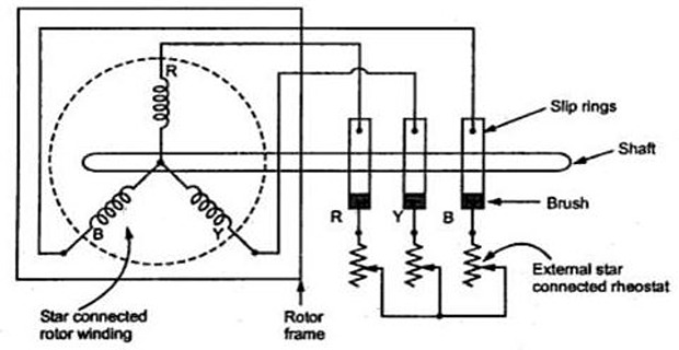
The rotor carries a proper three-phase winding brought out to slip rings, so that external resistance can be inserted.
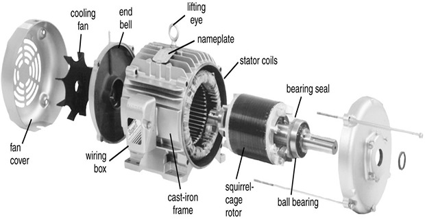
The Rotating Transformer
As a general rule, conversion of electrical power into mechanical power takes place in the rotating part of an electric motor.
In DC motors, the electric power is conducted directly to the armature — the rotating part — through brushes and a commutator. A DC motor may therefore be called a conduction motor.
In AC motors, the rotor does not receive electric power by conduction but by induction, in exactly the same way as a two-winding transformer receives its power from the primary. Such motors are therefore known as induction motors.
An induction motor can be treated as a rotating transformer: the primary winding is stationary, but the secondary is free to rotate.
Everything from Part 3 carries over — EMF equation, ampere-turn balance, equivalent circuit, leakage reactance — with one modification. Because the secondary moves, the frequency of the EMF induced in it is not the supply frequency \(f\) but \(sf\), where \(s\) is the slip.
Of all the AC motors, the polyphase induction motor is the one most extensively used for industrial drives of every kind. Chapters 58 to 64 develop its behaviour; this chapter builds the machine.
The Stator
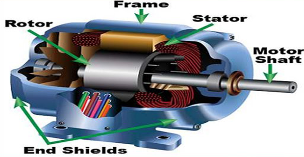
The stator is essentially identical in both types of machine.
| Part | Construction | Purpose |
|---|---|---|
| Frame or yoke | Cast iron or fabricated steel, often finned | Mechanical support, protection, and a path for heat to escape |
| Stator core | Laminations of silicon steel, 0.35 to 0.5 mm, insulated and stacked | Carries the alternating flux with low eddy-current loss (Chapter 7) |
| Stator slots | Punched on the inner periphery of the laminations | House the winding, and hold it against the forces of a fault |
| Stator winding | Three-phase, distributed, star or delta connected | Produces the rotating magnetic field |
The three-phase winding is arranged for a definite number of poles, and that choice fixes the speed of the rotating field:
At a fixed supply frequency the only speeds available are those given by integer pole numbers — 3000, 1500, 1000, 750 rev/min and so on at 50 Hz. Chapter 59 derives why the field rotates at all.
The winding is distributed over several slots per pole per phase rather than concentrated in one, which improves the waveform and uses the iron more evenly — at the cost of a small reduction in EMF measured by the distribution factor.
Problem. A three-phase induction motor nameplate reads 50 Hz, 1440 rev/min. Deduce the number of poles, the synchronous speed, the slip and the rotor frequency.
Available synchronous speeds at 50 Hz.
| Poles | 2 | 4 | 6 | 8 | 12 |
|---|---|---|---|---|---|
| \(N_s\) (rev/min) | 3000 | 1500 | 1000 | 750 | 500 |
Deduction. A running speed of 1440 must lie just below a synchronous speed, and the only candidate is 1500. Hence \(P = 4\).
Slip.
Rotor frequency.
Comment. A full-load slip of 4 % is typical of a small machine; large motors run at 1 to 2 %. The nameplate speed alone tells you the pole number, because only certain synchronous speeds exist, and running speed is always a few percent below one of them.
The rotor frequency of 2 Hz is worth noting now, since Chapter 60 depends on it: the rotor iron is worked at a very low frequency in normal running, so rotor core loss is negligible — quite unlike the stator, which always sees the full 50 Hz.
Problem. A 4-pole, three-phase stator has 36 slots. Find the slots per pole, the slots per pole per phase, the slot angle, the full-pitch coil span, and the distribution factor.
Slots per pole.
Slots per pole per phase.
Slot angle. One pole pitch spans \(180^{\circ}\) electrical over 9 slots:
Full-pitch coil span is one pole pitch, that is 9 slots.
Distribution factor.
Comment. Distributing the winding over three slots per pole per phase costs 4.0 % of the EMF compared with concentrating it all in one slot. That is a price worth paying: the concentrated winding would produce a badly stepped MMF wave rich in harmonics, and would concentrate all the heat in a third of the slots.
Machines are also usually short-pitched — the coil spans fewer than 9 slots — which introduces a further pitch factor below unity but suppresses particular harmonics, chiefly the fifth and seventh. The combined winding factor \(k_w = k_dk_p\) is what appears in the EMF equation.
The Squirrel-Cage Rotor
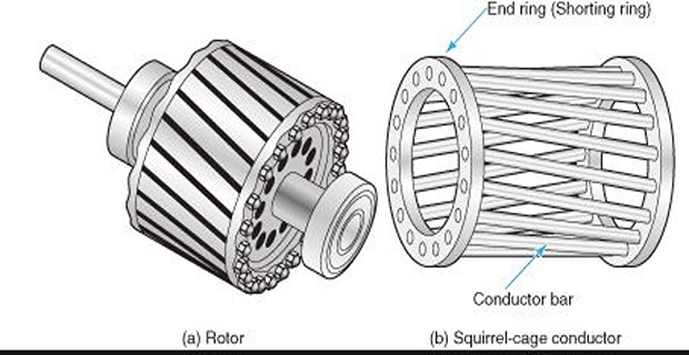
The cage rotor is the simplest rotating structure in all of electrical engineering, and about 90 % of induction motors in service use it.
A laminated cylindrical core with slots near the surface, usually semi-closed or fully closed.
Each slot holds one uninsulated bar of copper, aluminium or an alloy. No insulation is needed because the induced rotor EMF is very small and the bars are all at nearly the same potential.
The bars are permanently short-circuited at both ends by heavy end rings of the same material, brazed or, in small machines, cast integrally with the bars.
There are no brushes, no slip rings and no external connections. The rotor circuit is entirely self-contained.
There is no winding to fail, no insulation to age, no brush to wear, and no connection to loosen. The rotor is a solid piece of metal that happens to conduct in the right pattern.
A cage rotor also adapts automatically to the number of stator poles, because the currents induced in the bars arrange themselves into whatever pole pattern the stator field demands. A wound rotor must be wound for a specific pole number.
Look at any cage rotor and the end rings are far more massive than the bars. The reason is that each end ring collects the current from many bars.
The bar currents are not in phase — they are distributed around the rotor with the pole pattern — so the end-ring current is a phasor sum, not an arithmetic one. The result is
where \(p\) is the number of pole pairs and \(S_2\) the number of rotor bars. Example 57.3 shows this is typically twice the bar current or more.
Problem. A 4-pole cage rotor has 30 bars, each carrying 100 A. Find the current in the end rings.
Pole pairs.
The angle.
End-ring current.
Comment. The end ring carries 2.40 times the current of any single bar. That is why the rings are of much heavier section than the bars — a fact plainly visible on any cage rotor but rarely explained.
Note how the factor depends on the design. Fewer bars, or more poles, make the angle larger, its sine larger, and the end-ring current smaller relative to the bar current. A 2-pole machine with the same 30 bars would give \(\pi/30 = 6^{\circ}\) and a factor of 4.78 — nearly twice as demanding on the rings.
The end rings also carry no useful torque-producing current. Their \(I^{2}R\) loss is pure waste, which is why they are made generously large in efficient designs.
The Wound (Slip-Ring) Rotor
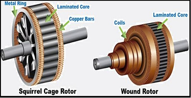
The rotor carries a proper three-phase winding of insulated conductors, distributed in slots exactly like the stator winding and wound for the same number of poles.
The three phases are usually star connected, and the three free ends are brought out to three slip rings mounted on the shaft.
Carbon brushes bearing on the slip rings connect the rotor circuit to an external three-phase variable resistance.
Once the machine is running, the external resistance is cut out and the slip rings are short-circuited. Many machines then lift the brushes to reduce wear.
High starting torque with low starting current. Adding rotor resistance moves the point of maximum torque towards standstill, so full torque can be had at start.
Speed control by varying the resistance — at the cost of efficiency, since the extra power is dissipated as heat.
Smooth acceleration of high-inertia loads, with the resistance cut out in steps.
Chapter 62 will show that maximum torque itself is unchanged by rotor resistance — only the slip at which it occurs moves. That is the whole basis of the slip-ring machine.
The price is real: slip rings and brushes to maintain, a more expensive rotor, and lower reliability. A slip-ring motor is bought only when its starting behaviour is genuinely needed — increasingly it is displaced by a cage motor with a variable-frequency drive.
Choosing the Rotor Slot Number
The number of rotor slots cannot be chosen freely. Certain combinations with the stator slot number cause the machine to misbehave badly, and the rules that avoid them are among the most practical results in machine design.
If \(S_2 = S_1\), every rotor slot faces a stator slot at the same instant. The reluctance torque locks the rotor and it refuses to start at all.
Certain differences produce strong harmonic fields with their own synchronous speeds. The motor runs stably at a low speed — often a seventh of synchronous — and will not accelerate past it.
In practice \(S_2\) is made unequal to \(S_1\) and preferably not a simple multiple relation to it, and the bars are skewed as further insurance.
Problem. A 4-pole machine has 36 stator slots. Which rotor slot numbers between 24 and 48 are forbidden, and is 30 a safe choice?
Forbidden by the cogging rule.
Forbidden by the difference rules, with \(P = 4\):
The forbidden set in range.
Testing 30.
Not an integer multiple of \(P\) at all, so none of the rules is violated. 30 is a safe choice.
Comment. Notice that the forbidden numbers are all multiples of 4 apart from 36 — that is, every value with the same parity relationship to the pole number. The safe choices are those whose difference from 36 is not a multiple of the pole number, which for a 4-pole machine means avoiding all multiples of 4.
This is why rotor slot numbers so often look arbitrary — 26, 30, 34, 46 — rather than the round figures one might expect. They are chosen precisely to be awkward relative to the stator.
Why the Bars Are Skewed
Cage rotor bars are almost never parallel to the shaft. They are set at a slight angle — skewed — usually by about one stator slot pitch over the length of the core.
Prevents cogging. A skewed bar cannot align with a stator slot along its whole length, so the reluctance torque that locks the rotor is largely cancelled.
Reduces harmonic torques and so suppresses crawling.
Quieter and smoother running, because the slot-frequency force pulsations are averaged out.
Better distribution of stress in the bars and less risk of magnetic noise.
The cost is a slight reduction in the induced rotor EMF, since the bar no longer lies wholly under one point of the flux wave. This is measured by the skew factor:
where \(\alpha\) is the skew angle in electrical radians. Example 57.5 shows how small the penalty is.
Problem. The 4-pole machine of Example 57.2 has 36 stator slots, and the rotor bars are skewed by one stator slot pitch. Find the skew angle in electrical degrees and the skew factor.
Slot pitch in mechanical degrees.
Converting to electrical degrees, multiplying by the number of pole pairs:
Skew factor.
EMF lost.
Comment. Skewing costs about half a percent of the rotor EMF and eliminates cogging, most crawling, and a great deal of noise. Few design decisions buy so much for so little.
Compare the two winding factors of this machine: the distribution factor costs 4.0 % and the skew factor 0.5 %. Both are deliberate sacrifices of EMF made to obtain a better waveform and better mechanical behaviour, and both are recovered simply by winding a few more turns.
Note that the skew must be reckoned in electrical degrees. On this 4-pole machine one mechanical slot pitch of 10° becomes 20° electrical; on an 8-pole machine of the same slot count it would be 40° electrical, and the factor would fall to 0.9797 — four times the penalty for the same physical skew.
Comparison of the Two Types
| Squirrel cage | Wound rotor | |
|---|---|---|
| Rotor winding | Bars and end rings, uninsulated | Insulated three-phase winding |
| External connection | None | Three slip rings and brushes |
| Starting torque | Moderate, typically 1.5 to 2 × full load | High — up to maximum torque at standstill |
| Starting current | High, 5 to 7 × full load | Lower, controlled by the resistance |
| Speed control | Not by rotor means | By rotor resistance, at poor efficiency |
| Maintenance | Almost none | Brushes and rings need attention |
| Cost | Low | Appreciably higher |
| Efficiency at full load | Slightly higher | Slightly lower |
| Robustness | Extremely rugged | Less so |
Advantages and Disadvantages
Simple and extremely rugged, almost unbreakable construction — especially the squirrel-cage type.
Low cost and reliable.
Sufficiently high efficiency. In normal running no brushes are needed, so frictional losses are reduced, and the power factor is reasonably good.
Requires minimum maintenance.
It starts from rest, needs no extra starting motor, and does not have to be synchronised.
The starting arrangement is simple, especially for the cage type.
Its speed cannot be varied without sacrificing some of its efficiency.
Just like a DC shunt motor, its speed decreases with increase in load.
Its starting torque is somewhat inferior to that of a DC shunt motor.
It always draws a lagging power factor, poor at light load, because the magnetising current crosses an air gap.
Starting current is high — five to seven times full load for a cage motor started direct on line.
The last two deserve emphasis because they shape so much of Part 4. The air gap makes the magnetising current far larger than in a transformer of the same rating — often 30 to 50 % of full-load current rather than 2 to 6 % — and that is the whole reason for the induction motor's characteristic lagging power factor.
Applications
Pumps
Compressors
Small fans
Mixers
Toys
High-speed vacuum cleaners
Electric shavers
Drilling machines
Lifts
Cranes
Hoists
Large-capacity exhaust fans
Driving lathe machines
Crushers
Conveyors, mills and machine tools generally
Summary and Common Mistakes
AC motors are synchronous or asynchronous (induction); induction motors are cage or wound rotor.
An induction motor is a rotating transformer: the rotor receives power by induction, not conduction, and the rotor EMF is at frequency \(sf\).
The machine must slip — at synchronous speed there is no relative motion, no rotor EMF and no torque.
The stator is a laminated slotted core carrying a distributed three-phase winding; the pole number fixes \(N_s = 120f/P\).
Distribution costs EMF — \(k_d = \sin(q\beta/2)/(q\sin(\beta/2))\), about 0.96 for \(q=3\) — but improves the waveform.
The cage rotor is uninsulated bars short-circuited by end rings, with no external connection. The end ring carries \(I_b/[2\sin(\pi p/S_2)]\), typically over twice the bar current.
The wound rotor brings a three-phase winding out to slip rings so that external resistance can raise starting torque and control speed.
Rotor slots must satisfy \(S_2 \ne S_1\) and \(S_2 - S_1 \ne \pm P, \pm2P, \pm3P, \pm5P\), to avoid cogging and crawling.
Skewing by one slot pitch costs about 0.5 % of EMF and removes cogging, harmonic torques and much noise.
Cage motors win on cost, robustness and maintenance; wound rotors win only on starting torque and rotor-side speed control.
| Quantity | Formula | Notes |
|---|---|---|
| Synchronous speed | \(N_s = \dfrac{120f}{P}\) | only certain speeds exist |
| Slip | \(s = \dfrac{N_s - N}{N_s}\) | — |
| Rotor frequency | \(f_r = sf\) | 2 Hz at 4 % slip |
| Slots per pole per phase | \(q = \dfrac{S_1}{Pm}\) | — |
| Slot angle | \(\beta = \dfrac{180^{\circ}}{S_1/P}\) | electrical |
| Distribution factor | \(k_d = \dfrac{\sin\left(q\beta/2\right)}{q\sin\left(\beta/2\right)}\) | 0.9598 for \(q=3\) |
| End-ring current | \(I_e = \dfrac{I_b}{2\sin\left(\pi p/S_2\right)}\) | 2.40 \(I_b\) in Ex. 57.3 |
| Skew factor | \(k_s = \dfrac{\sin\left(\alpha/2\right)}{\alpha/2}\) | \(\alpha\) in electrical radians |
| Slot rules | \(S_2 \ne S_1\); \(S_2 - S_1 \ne \pm P, \pm2P, \pm3P, \pm5P\) | cogging, crawling |
Thinking an induction motor can reach synchronous speed. At \(s = 0\) there is no rotor EMF and no torque.
Believing the cage rotor is wound for a pole number. It adapts automatically to whatever the stator produces.
Assuming the end rings carry the same current as the bars. They carry over twice as much.
Insulating cage bars. They need none — the rotor EMF is a few volts.
Choosing \(S_2 = S_1\). The motor will cog and refuse to start.
Measuring skew in mechanical degrees. The skew factor needs electrical degrees, so the pole number matters.
Expecting the rotor iron to be worked at supply frequency. It sees only \(sf\), about 2 Hz in normal running.
Confusing the two rotor types on efficiency. The wound rotor is slightly less efficient, not more.
Leaving external rotor resistance in circuit while running. It wastes power; it is cut out and the rings shorted.
Attributing the poor power factor to the winding. It is the air gap, which makes the magnetising current large.
Chapter Review
For nameplate problems, find the synchronous speed just above the running speed — that fixes the pole number at once.
P57.1 A three-phase induction motor runs at 960 rev/min from a 50 Hz supply. Find the number of poles, the slip and the rotor frequency.
Show answer
The synchronous speed just above 960 is 1000, so\[P = \frac{120(50)}{1000} = 6\ \text{poles}\]\[s = \frac{1000 - 960}{1000} = 0.0400 = 4.00\,\%\]\[f_r = (0.04)(50) = 2.00~\mathrm{Hz}\]P57.2 An 8-pole, 50 Hz motor has a full-load slip of 3 %. Find the synchronous and full-load speeds.
Show answer
\[N_s = \frac{120(50)}{8} = 750~\mathrm{rev/min}\]\[N = (1 - s)N_s = (0.97)(750) = 727.5~\mathrm{rev/min}\]P57.3 A 6-pole, three-phase stator has 54 slots. Find \(q\), the slot angle and the distribution factor.
Show answer
\[q = \frac{54}{(6)(3)} = 3, \qquad \frac{S_1}{P} = 9, \qquad \beta = \frac{180^{\circ}}{9} = 20^{\circ}\]The same as Example 57.2, since \(q\) and \(\beta\) are the same.\[k_d = \frac{\sin30^{\circ}}{3\sin10^{\circ}} = 0.9598\]P57.4 A 6-pole cage rotor has 44 bars each carrying 250 A. Find the end-ring current.
Show answer
\[p = 3, \qquad \frac{\pi p}{S_2} = \frac{3\pi}{44} = 0.21420~\mathrm{rad} = 12.27^{\circ}\]A factor of 2.35 — again over twice the bar current.\[I_e = \frac{250}{2\sin12.27^{\circ}} = \frac{250}{(2)(0.21257)} = 588.0~\mathrm{A}\]P57.5 A 4-pole machine has 48 stator slots. List the forbidden rotor slot numbers between 30 and 66.
Show answer
\[S_2 = 48 \quad (=S_1), \qquad 44,\ 52 \quad (\pm P), \qquad 40,\ 56 \quad (\pm2P)\]The full forbidden set is \(\left\{28, 36, 40, 44, 48, 52, 56, 60, 68\right\}\), of which \(\left\{36, 40, 44, 48, 52, 56, 60\right\}\) lie in the range 30 to 66 — the values 28 and 68 fall just outside it.\[36,\ 60 \quad (\pm3P), \qquad 28,\ 68 \quad (\pm5P)\]A good choice would therefore be 38, 42, 46, 50, 54, 58 or 62. Note that \(\pm5P = \pm20\), not \(\pm16\) — it is easy to lose count of the multiples, so it is worth writing each one out.
P57.6 An 8-pole machine with 48 stator slots has its bars skewed by one stator slot pitch. Find the skew factor and compare with a 4-pole machine of the same slot count.
Show answer
8 poles (\(p = 4\)):\[\text{slot pitch} = \frac{360^{\circ}}{48} = 7.50^{\circ}\ \text{mechanical}\]4 poles (\(p = 2\)):\[\alpha = (7.50)(4) = 30.00^{\circ} = 0.52360~\mathrm{rad}, \quad k_s = \frac{\sin15^{\circ}}{0.26180} = 0.98862\]The same physical skew costs 1.14 % on 8 poles but only 0.29 % on 4 — four times as much, since the penalty depends on the electrical angle.\[\alpha = 15.00^{\circ} = 0.26180~\mathrm{rad}, \quad k_s = \frac{\sin7.5^{\circ}}{0.13090} = 0.99714\]P57.7 Explain why an induction motor is called a rotating transformer, and why it cannot run at synchronous speed.
Show answer
Rotating transformer. In a DC motor the armature receives power by conduction, through brushes and commutator. In an induction motor the rotor receives no conducted power at all — the stator sets up a rotating field, and the rotor conductors have EMF induced in them exactly as a transformer secondary does. The stator is the primary, the rotor the secondary, and the only difference from Part 3 is that this secondary is free to turn.Why it cannot reach synchronous speed. Torque requires rotor current, rotor current requires rotor EMF, and rotor EMF requires the rotor conductors to cut the rotating field.
\[N = N_s \quad\Longrightarrow\quad \text{relative speed} = 0 \quad\Longrightarrow\quad E_r = 0 \quad\Longrightarrow\quad I_r = 0 \quad\Longrightarrow\quad T = 0\]The machine would produce no torque at all and could not even overcome its own friction. It must therefore always run a little below synchronous speed — hence "asynchronous", and hence the slip as the fundamental variable of Part 4.
P57.8 Why is the end-ring current larger than the bar current, and what follows for the design?
Show answer
Each end ring collects current from many bars, but those bar currents are not in phase — they are distributed around the rotor following the pole pattern. The ring current is therefore a phasor sum of the contributions, givingFor a 4-pole rotor with 30 bars this is \(2.40\,I_b\).\[I_e = \frac{I_b}{2\sin\left(\pi p/S_2\right)}\]Design consequences. The rings must be of much heavier cross-section than the bars — plainly visible on any cage rotor. Their \(I^{2}R\) loss produces no torque whatever, so it is pure waste and the rings are made generously large in efficient designs.
Note that the factor depends on the design: fewer poles make it worse. A 2-pole rotor with the same 30 bars gives \(\pi/30 = 6^{\circ}\) and a factor of 4.78.
P57.9 Explain cogging and crawling, and how each is prevented.
Show answer
Cogging (magnetic locking). If the rotor and stator have equal slot numbers, every rotor slot faces a stator slot simultaneously. The reluctance is then minimum at that alignment, and the resulting reluctance torque locks the rotor magnetically. The motor refuses to start at all, however much current it draws.Crawling. The stator MMF is not a pure sine wave — it contains space harmonics, chiefly the fifth and seventh. Each harmonic produces its own rotating field with its own synchronous speed, one seventh of the fundamental for the seventh harmonic. If the harmonic torque is strong enough, the motor runs stably at that low speed and will not accelerate past it.
Prevention:
Choose \(S_2 \ne S_1\), and avoid \(S_2 - S_1 = \pm P, \pm2P, \pm3P, \pm5P\).
Skew the rotor bars, so that no bar can align with a stator slot along its whole length.
Use a distributed and short-pitched stator winding to suppress the harmonics at source.
P57.10 When is a slip-ring motor worth its extra cost?
Show answer
Only when its starting behaviour is genuinely needed. External rotor resistance moves the point of maximum torque towards standstill, givingHigh starting torque with low starting current — up to maximum torque at rest.
Smooth acceleration of a high-inertia load, with resistance cut out in steps.
Some speed control, at the cost of efficiency.
The price is slip rings and brushes to maintain, a costlier rotor, lower reliability and slightly lower efficiency.
Typical applications are therefore cranes, hoists, crushers and mills — loads that must be started under full torque or that have large inertia.
The modern qualification: a cage motor with a variable-frequency drive now gives better starting torque and far better speed control than rotor resistance ever could, and without the maintenance. New slip-ring installations are consequently rare.
MCQ 1. An induction motor is best described as:
(a) a conduction motor (b) a rotating transformer (c) a synchronous machine (d) a DC machineShow answer
(b) a rotating transformer — the rotor receives power by induction.MCQ 2. At synchronous speed the torque of an induction motor is:
(a) maximum (b) zero (c) negative (d) ratedShow answer
(b) zero — no relative motion, no EMF, no current.MCQ 3. A 50 Hz motor running at 1440 rev/min has:
(a) 2 poles (b) 4 poles (c) 6 poles (d) 8 polesShow answer
(b) 4 poles, since \(N_s = 1500\) rev/min.MCQ 4. Cage rotor bars are:
(a) insulated (b) uninsulated (c) brought out to slip rings (d) open-circuitedShow answer
(b) uninsulated — the rotor EMF is only a few volts.MCQ 5. The end-ring current of a cage rotor is typically:
(a) less than the bar current (b) equal to it (c) about twice it (d) ten times itShow answer
(c) about twice it — 2.40 times in Example 57.3.MCQ 6. Cogging occurs when:
(a) \(S_2 = S_1\) (b) \(S_2 \ne S_1\) (c) the bars are skewed (d) the slip is highShow answer
(a) \(S_2 = S_1\), and the motor will not start.MCQ 7. Skewing the rotor bars by one slot pitch costs roughly:
(a) 0.5 % of EMF (b) 5 % (c) 15 % (d) nothingShow answer
(a) 0.5 % of EMF for a 4-pole machine — very cheap insurance.MCQ 8. External rotor resistance can be added only in:
(a) a cage motor (b) a slip-ring motor (c) both (d) neitherShow answer
(b) a slip-ring motor — the cage has no external connection.MCQ 9. The rotor iron of a running induction motor is worked at:
(a) supply frequency (b) \(sf\) (c) twice supply frequency (d) zeroShow answer
(b) \(sf\) — about 2 Hz at 4 % slip, so rotor core loss is negligible.MCQ 10. The induction motor's lagging power factor is caused chiefly by:
(a) the air gap (b) copper loss (c) the end rings (d) skewingShow answer
(a) the air gap, which makes the magnetising current large.
Classify AC motors and place the induction motor among them.
Explain why an induction motor is called a rotating transformer.
Describe the construction of the stator and the purpose of each part.
Describe the squirrel-cage rotor and explain why the end rings are heavy.
Describe the wound rotor and explain what the external resistance achieves.
State the rules for choosing the rotor slot number, and the faults they prevent.
Explain skewing, its benefits and its cost.
Compare the two rotor types and state where each is used.
The machine is now built. Chapter 58 puts it to work, following the chain that produces torque: the stator field rotates, the stationary rotor conductors are cut by it, EMF is induced, current flows in the short-circuited rotor, and the force on those current-carrying conductors in the field produces torque in the direction that reduces the relative motion — which is Lenz's law of Chapter 10 expressed as a mechanical effect.
Chapter 59 then proves the result that everything rests on: that three windings displaced by \(120^{\circ}\) in space, carrying currents displaced by \(120^{\circ}\) in time, produce a field of constant magnitude rotating at constant speed — of amplitude 1.5 times that of one phase alone.
Chapter 60 develops slip properly, showing how rotor frequency, rotor EMF and rotor reactance all vary with it, and Chapter 61 assembles those into the torque equation. The characteristic torque-slip curve of Chapter 62 then follows, with its striking result that the maximum torque does not depend on rotor resistance at all — only the slip at which it occurs does, which is exactly what makes the slip-ring machine of Section 57-5 useful.